The steam may be water leaking from the intake manifold and squirting out on the header pipe. The last bolt on the rear of the lower intake manifold is next to the water passage for the cylinder head.
Check to see that you don't have a leaking valve cover gasket dumping oil on the header or the PCV valve disconnected and pointing at the header.
Instant red hot headers - possible lean mixture...
Check for presence of vacuum leaks by using a vacuum gauge. You should see 18"-21" of vacuum at 1000 RPM. Less than 16" would make me think vacuum leak. The PCV valve not installed correctly would also cause a vacuum leak.
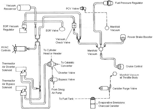
Diagram courtesy of Tmoss & Stang&2birds
Check fuel pressure – remove the cap from the Schrader valve behind the alternator and connect fuel pressure test gauge to Schrader valve. The fuel pressure regulator is located on the passenger side of the car behind the throttle body. Disconnect the small vacuum line from the fuel pressure regulator and plug the line. Leave the port where you removed the line uncapped and open to the atmosphere.
Start the car and observe the pressure: you should see 37-41 PSI at idle.
Be sure to unplug and reconnect the vacuum line to the fuel pressure regulator when you have finished your tests.
Fuel pressure test gauge are available for rent/loan at most major auto parts stores like AutoZone.
Dumping The computer diagnostic codes on 86-95 Mustangs
Revised 19-May-2009 to update drawing for dumping the codes on 86-88 Mustangs with no check engine light.
Dump the codes and see what the computer says is wrong…Codes may be present in the computer even if the Check Engine light isn’t on.
Here's the way to dump the computer codes with only a jumper wire or paper clip and the check engine light, or test light or voltmeter. I’ve used it for years, and it works great. You watch the flashing test lamp or Check Engine Light and count the flashes.
Be sure to turn off the A/C, and put the transmission in neutral when dumping the codes. Fail to do this and you will generate a code 67 and not be able to dump the Engine Running codes.
Dumping the Engine Running codes: The procedure is the same, you start the engine with the test jumper in place. Be sure the A/C is off and the transmission is in neutral. You'll get an 11, then a 4 and the engine will speed up to do the EGR test. After the engine speed decreases back to idle, it will dump the engine running codes.
Here's the link to dump the computer codes with only a jumper wire or paper clip and the check engine light, or test light or voltmeter. I’ve used it for years, and it works great. You watch the flashing test lamp or Check Engine Light and count the flashes.
See
Troublcodes.net Trouble Codes OBD & OBD2 Trouble Codes and Technical info & Tool Store. By BAT Auto Technical
If your car is an 86-88 stang, you'll have to use the test lamp or voltmeter method. There is no functional check engine light on the 86-88's except possibly the Cali Mass Air cars.
The STI has a gray connector shell and a white/red wire. It comes from the same bundle of wires as the self test connector.
89 through 95 cars have a working Check Engine light. Watch it instead of using a test lamp.
The STI has a gray connector shell and a white/red wire. It comes from the same bundle of wires as the self test connector.
WARNING!!! There is a single dark brown connector with a black/orange wire. It is the 12 volt power to the under the hood light. Do not jumper it to the computer test connector. If you do, you will damage the computer.
What to expect:
You should get a code 11 (two single flashes in succession). This says that the computer's internal workings are OK, and that the wiring to put the computer into diagnostic mode is good. No code 11 and you have some wiring problems.
Codes have different answers if the engine is running from the answers that it has when the engine isn't running. It helps a lot to know if you had the engine running when you ran the test.
Trouble codes are either 2 digit or 3 digit, there are no cars that use both 2 digit codes and 3 digit codes.
Alternate methods:
For those who are intimidated by all the wires & connections, see
Actron® for what a typical hand scanner looks like. Normal retail price is about $30 or so at AutoZone or Wal-Mart.
Or for a nicer scanner see
Equus - Digital Ford Code Reader (3145) – It has a 3 digit LCD display so that you don’t have to count flashes or beeps.. Cost is $30.
See the following website for some help from Tmoss (diagram designer) & Stang&2Birds (website host) for help on 88-95 wiring Mustang FAQ - Engine Information Everyone should bookmark this site.
Ignition switch wiring
http://www.veryuseful.com/mustang/tech/engine/images/IgnitionSwitchWiring.gif
Fuel, alternator, A/C and ignition wiring
http://www.veryuseful.com/mustang/tech/engine/images/fuel-alt-links-ign-ac.gif
Complete computer, actuator & sensor wiring diagram for 88-91 Mass Air Mustangs
http://www.veryuseful.com/mustang/tech/engine/images/88-91_5.0_EEC_Wiring_Diagram.gif
Complete computer, actuator & sensor wiring diagram for 91-93 Mass Air Mustangs
http://www.veryuseful.com/mustang/tech/engine/images/91-93_5.0_EEC_Wiring_Diagram.gif
Complete computer, actuator & sensor wiring diagram for94-95 Mass Air Mustangs
http://www.veryuseful.com/mustang/tech/engine/images/94-95_5.0_EEC_Wiring_Diagram.gif
Vacuum diagram 89-93 Mustangs
http://www.veryuseful.com/mustang/tech/engine/images/mustangFoxFordVacuumDiagram.jpg
HVAC vacuum diagram
http://www.veryuseful.com/mustang/tech/engine/images/Mustang_AC_heat_vacuum_controls.gif
TFI module differences & pinout
http://www.veryuseful.com/mustang/tech/engine/images/TFI_5.0_comparison.gif
Fuse box layout
http://www.veryuseful.com/mustang/tech/engine/images/MustangFuseBox.gif
 That was not helpful...