What causes no advance?

Hi,

I'm having some trouble with my 1986 5.0 with a mass air conversion. There is no timing advance during reving up.

After the mass air conversion (not inmediately thereafter) a problem accured, power went down and the tailpipe became black, there were stubles, mostly around 1800 rpm.

I checked the obvious, vacuum leaks, IAC, tps etc. Nothing found.

Then one day the show went over and I was stranded after 5 minutes driving. After some cooling down it started again. I blamed the TFI.

I also checked for codes, it came up with a 34 and a 18.

Before installation of the TFI I checked the timing: 12 degrees but no advance at all!

After installation it started up but stil a bit rough. I checked the timing, it was still at 12 degrees but no advance. mmmmm

I checked the spout, seems to be good, 8 volts with engine running (measured at the EEC and at the spout, then with engine of at the TFI connector. No problem found. (with engine of the voltage dropped in time from 8 volts to less than 2).

No I'm confused. What more can I check? Can the EEC be bad?

Can the hall pickup be defictive?

How do I measure PIP.

How does the timing advance work (which signal triggers what)?

Thank,

Adam

(a 5.0 lover from the Netherlands)

data: 5.0 with a A9P (during conversion all soldered), T5, MSD blaster 3, full stainless exhaust, flowmasters, no converters, 70 mm throttle body and EGR spacer, 76 mm air meter (C&L) for 19 lbs (yellow/gold tube), C&L airpipe etc.
 
  • Sponsors (?)


Code 18 - SPOUT out or wiring fault - look missing SPOUT jumper, short to ground or open circuit in SPOUT wiring going back to the computer. Possible bad TFI.

The SPOUT enables the distributor to advance the timing beyond the base setting. Without a working SPOUT, you are locked down to the timing you set with the timing light.

Checking the SPOUT wiring
Tools needed:

DVM or Ohmmeter
10 MM wrench
Phillips screwdriver.
6 ft 16 or 18 gauge jumper wire with alligator clips on each end.

Anytime you make resistance checks, the circuit under test must not be powered on. If it is powered up during the test, your readings will be wrong and you may damage the meter. Do not touch the probe tips when making resistance measurements. If you do, your readings may be inaccurate.

Remove the SPOUT connector from the ignition harness by the distributor. Remove the passenger side kick panel and loosen the 10 MM bolt that secures the computer wiring connector. Use your DVM to measure the resistance between ground and pin 38 (yellow/lt green wire): you should see and infinite open circuit. Keep the DVM connected to pin 38 (you may need a helper at this point). Insert the DVM lead you previously had connected to the body ground into the computer side of the SPOUT connector. You may need some extra wire to extend the test lead, so have some 16-18 gauge insulated wire handy. If you extend the test lead, remember that the quality of the connections may affect your readings. You should see less than 2.0 Ohms: more than that indicates a wiring problem

The following is a view from the computer side of the computer wiring connector.
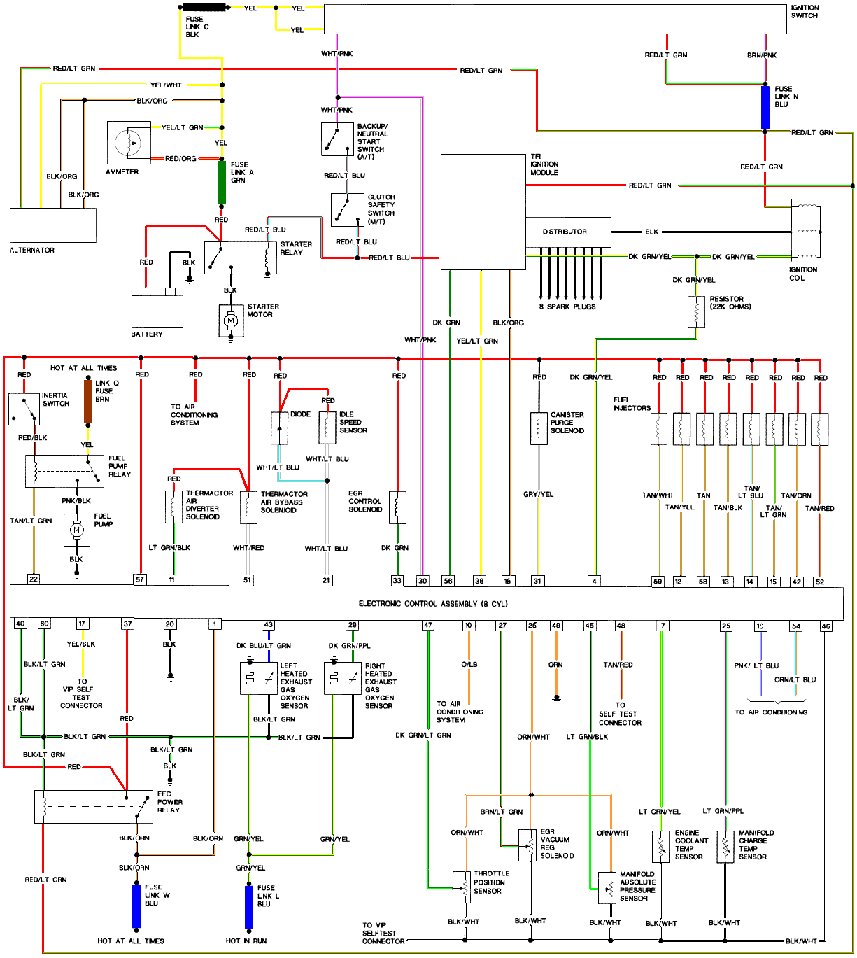
eec04.gif


Diagrams courtesy of Tmoss & Stang&2birds
Mustang-86-Mustang-ECC-EFI.gif


See the following website for some help from Tmoss (diagram designer) & Stang&2Birds
(website host) for help on 86-95 5.0 Mustang wiring Mustang FAQ - Engine Information Everyone should bookmark this site.


Ignition switch wiring
http://www.veryuseful.com/mustang/tech/engine/images/IgnitionSwitchWiring.gif

Fuel, alternator, A/C and ignition wiring
http://www.veryuseful.com/mustang/tech/engine/images/fuel-alt-links-ign-ac.gif

Complete computer, actuator & sensor wiring diagram for 88-91 5.0 Mass Air Mustangs
http://www.veryuseful.com/mustang/tech/engine/images/88-91_5.0_EEC_Wiring_Diagram.gif

Complete computer, actuator & sensor wiring diagram for 91-93 5.0 Mass Air Mustangs
http://www.veryuseful.com/mustang/tech/engine/images/91-93_5.0_EEC_Wiring_Diagram.gif

Complete computer, actuator & sensor wiring diagram for 94-95 5.0 Mass Air Mustangs
http://www.veryuseful.com/mustang/tech/engine/images/94-95_5.0_EEC_Wiring_Diagram.gif

1986 Mustang 5.0 1986 EEC/ ECM. EFI wiring schematic,
http://www.veryuseful.com/mustang/tech/engine/images/Mustang-86-Mustang-ECC-EFI.gif

Vacuum diagram 89-93 Mustangs
http://www.veryuseful.com/mustang/tech/engine/images/mustangFoxFordVacuumDiagram.jpg

HVAC vacuum diagram
http://www.veryuseful.com/mustang/tech/engine/images/Mustang_AC_heat_vacuum_controls.gif

TFI module differences & pinout
http://www.veryuseful.com/mustang/tech/engine/images/TFI_5.0_comparison.gif

Fuse box layout
http://www.veryuseful.com/mustang/tech/engine/images/MustangFuseBox.gif
 
bad EEC?

Hi,

I've found some time to check.

I checked the resistance. There is no short with ground (infinity). And no break in the wiring (0.6 ohms).

I also replaced my distributer with a new one (with a new TFI). No results.

Am I looking at a malfunctioning EEC? Or am I doing something wrong.

I'm about to go back to speed density and see if it is the same (to pinpoint the EEC)

Kind regards,

Adam
 
The only thing left is either a bad SPOUT connector or a bad computer.
Be sure to put the SPOUT in and check the wiring from the TFI connector to the computer connector if you haven't already done so. You should see less than 1.5 Ohms.
 
I installed the old speed density computer (with re-ordered wiring,38 back to 51 and 32 back to 11), but still no advance. That rules out the EEC to my opinion.

I also checked the spout connection (no resistance from terminal 36 at EEC to the TFI.

I want to check the wiring at the terminal of the EEC. Also every signal from the EEC to the TFI.

Strange...

regards,

Adam
 
I don' t know if this will help or not but when I did my mass air conv my car it died about a week later(back in 2002). I ran the wires to the mass air meter a little too close to the exhaust and they touched the exhaust and melted and shorted out. all it ended up being was the inline fuse for the computer. Another stang still on the road thanks to jrichker!!!!
 
Checked all the wires regarding ignition. No problems found so far.

But in the diagram there is a black wire between the distributor and the ignition coil. Where is this wire?

My book says for code 18: loss of tach signal. Where does the tach signal for the EEC come from? Is it pin 4?

regards,
Adam
 
SOLVED

Been measuring everything. Need a scope for more accurate measurements.

As a last fallback I installed the old speed density EEC back.

Solved! I must have solved a double problem during all the measurements and cleaning. Or I was to quick with my conclusion.

So the EEC is to blame.
Opening the EEC showed a capacitor (0.10 cents) which has been leaking and damaged 2 lines. I'm trying to repair it myself.

thanks for everything,

regards,

Adam
 
is there any way to advance the timing on thick film (gray modules) for us with carb set up

Timing on a TFI car is controled by the EEC.

The easiest way to add timing and use a TFI ignition is to use a MSD box (timing computer or a AL2).

But why should you use a TFI? To my opinion a Petronic unit has all the advantages of electronic ignition.

regards,

Adam
 
the reason for thick film is because of weird distributor that was in donner motor
88 ltd roller---the shaft is smaller and the longer from the gear down (1 inch -most 5.0's mine 1 1/2 inch) cannot find distributor with advance capabilities