Car Dies- WEIRD

Strype

Cuthbert catcher
Founding Member
May 11, 1999
61
35
104
Huntsvegas, AL
1992 GT, Umpteen K miles, 5 sp, HCI, bolt ons, taurus fan

This car is my friend's. We are stumped. Here are the symptoms:

* Car dies intermitantly when driven
- Both tachometers (monster and factory) die
- Motor goes for a bit, stumbles into a stall
- When you crank it, the motor turns
- All of the sudden after a few minutes, it cranks back up
- We checked for spark but it cranked right back up last time
- He left it running for 3 hours at idle and it never died :scratch:

What he's changed:
- Fuel Pump
- Coil
- ignition module (x2)
- distributor
- fuel pump
- some other stuff if he chimes in he can tell you

Have any of you ever had this problem? We can't use the check list because when it dies, it cranks right back up.

PS: This is his daily driver. :(
 
  • Sponsors (?)


Wow, you've nailed most of the things I was going to suggest. Sure sounds like the TFI. Are you spreading plenty of the heat sink paste around under the TFI module before you mount the new one ? It's really important for getting good heat transfer.
 
i'm the friend. the other parts replaced were ign. switch x2 fuel pump relay eec relay bypassed the inertia switch and checked for spark which i got but i beleive it was firing again so not sure if it was a good test .
 
You have hit all the suspect problems and replaced the high failure rate parts, so this isn't going to be easy.

Step 1.) Dump the codes. Find some, then post them here and we'll take a look to see if any of them are relevant to your current problem. Fuel pump wiring, sensors and several other systems will post codes to help pinpoint them as possible failure areas.

Step 2.) Don't find any codes, the problem is probably electrical with some loose connections: some critical part like the computer, fuel pump or TFI is losing power or signal and shutting down.
Do things like the radio, A/C or wipers, turn signals get crazy when the engine starts acting up? if so, look at the connector & wiring on the ignition switch very carefully. Tug lightly on the wires to make sure that none of them slide out of the connector shell and none of the wiring shows signs of overheating or other damage.

Step 3.) Check the wiring on the TFI modle: tug lightly on the wires to make sure that none of them slide out of the connector shell and none of the wiring shows signs of overheating or other damage.

Dumping The computer diagnostic codes on 86-95 Mustangs

Revised 19-May-2009 to update drawing for dumping the codes on 86-88 Mustangs with no check engine light.

Dump the codes and see what the computer says is wrong…Codes may be present in the computer even if the Check Engine light isn’t on.

Here's the way to dump the computer codes with only a jumper wire or paper clip and the check engine light, or test light or voltmeter. I’ve used it for years, and it works great. You watch the flashing test lamp or Check Engine Light and count the flashes.

Be sure to turn off the A/C, and put the transmission in neutral when dumping the codes. Fail to do this and you will generate a code 67 and not be able to dump the Engine Running codes.

Dumping the Engine Running codes: The procedure is the same, you start the engine with the test jumper in place. Be sure the A/C is off and the transmission is in neutral. You'll get an 11, then a 4 and the engine will speed up to do the EGR test. After the engine speed decreases back to idle, it will dump the engine running codes.

Here's the link to dump the computer codes with only a jumper wire or paper clip and the check engine light, or test light or voltmeter. I’ve used it for years, and it works great. You watch the flashing test lamp or Check Engine Light and count the flashes.

See Troublcodes.net Trouble Codes OBD & OBD2 Trouble Codes and Technical info & Tool Store. By BAT Auto Technical

B.jpg


F.jpg


If your car is an 86-88 stang, you'll have to use the test lamp or voltmeter method. There is no functional check engine light on the 86-88's except possibly the Cali Mass Air cars.

attachment.php


The STI has a gray connector shell and a white/red wire. It comes from the same bundle of wires as the self test connector.

89 through 95 cars have a working Check Engine light. Watch it instead of using a test lamp.

attachment.php


The STI has a gray connector shell and a white/red wire. It comes from the same bundle of wires as the self test connector.


WARNING!!! There is a single dark brown connector with a black/orange wire. It is the 12 volt power to the under the hood light. Do not jumper it to the computer test connector. If you do, you will damage the computer.

What to expect:
You should get a code 11 (two single flashes in succession). This says that the computer's internal workings are OK, and that the wiring to put the computer into diagnostic mode is good. No code 11 and you have some wiring problems.

Codes have different answers if the engine is running from the answers that it has when the engine isn't running. It helps a lot to know if you had the engine running when you ran the test.

Trouble codes are either 2 digit or 3 digit, there are no cars that use both 2 digit codes and 3 digit codes.

Alternate methods:
For those who are intimidated by all the wires & connections, see Actron® for what a typical hand scanner looks like. Normal retail price is about $30 or so at AutoZone or Wal-Mart.

Or for a nicer scanner see Digital Ford Code Reader (3145) – It has a 3 digit LCD display so that you don’t have to count flashes or beeps.. Cost is $30.
 
I didn't see anything mentioned in your first list about the computer itself. If the trouble shooting list by jrichker doesn't work you might try and swap out a known good computer from a similar car. Also check all of the engine grounds, especially the computer and injector grounds. Try cleaning and re-attaching the 10 pin connectors.
 
I was told last night that it appears the car is losing time with the spout connector in. It runs all the way to 0 degrees. I know that the timing is supposed to jump around with the spout connector in, but is it supposed to jump down in time?
 
Removing the SPOUT causes the ignition timing to drop back to whatever was set with the SPOUT out. That is how you set the base ignition timing.

To time the ignition: remove the SPOUT and use the timing light to check the timing against the marks on the harmonic balancer. Loosen the distributor hold down bolt and turn the distributor slowly until the light and the desired mark on the harmonic balancer line up. Tighten down the distributor hold down bolt and re-install the SPOUT jumper. When you put the SPOUT back in the computer will advance the spark. The timing may move around some with the SPOUT installed.
 
Exctly what we thought. Timing is set at 14 degrees... Something is losing time and I suspect a spout connector or computer. :scratch:

From what I gather, the spout connector is just a jumper that you disconnect to take the computer out of the equation to set timing. So there is hardly any way it can go bad. I'd still try to borrow a like computer from a similar car and see if that helps.
 
From what I gather, the spout connector is just a jumper that you disconnect to take the computer out of the equation to set timing. So there is hardly any way it can go bad. I'd still try to borrow a like computer from a similar car and see if that helps.

I'd just buy one... That car has a lot of original miles on it.

Id guess theres a bad ground somewhere

Could be... Hmmm.
 
Checked all grounds,even added some extra ones no change, now after replacing the pick up coil in the dizzy it has not died anymore but it does drop out rpms and come right back. trying a maf this evening a buddy had one to borrow to try said he had similar issue and thats what it was, it was shorting internally??????????:shrug:cross my fingers this is getting very very nerve racking. If it keeps it up I might change the sob to carb and say forget it with fords bs system
 
Hey would a bap sensor going bad cause a problem? i know these are supose to have a map sensor and it looks like someone put a bap w/no vacume line going to it but the car has had this since i got it 5 years ago where does the vac. line for the map go so i can get this to the right port. now i called the dealer where i know some techs and gave them the codes and they told me its just sencing the smog system deleted and i got the codes wrote down sitting at work they were a bank 1 and 2 smog valves or sensors.
 
Code 22 or 126 MAP (vacuum) or BARO signal out of range. The MAP or BARO sensor is pretty much the same sensor for both Mass Air & Speed Density cars. The main difference is where it is connected. Mass Air cars vent it to the atmosphere, while Speed Density cars connect it to the intake manifold vacuum. Its purpose is to help set a baseline for the air/fuel mixture by sensing changes in barometric pressure. The MAP or BAP sensor puts out a 5 volt square wave that changes frequency with variations in atmospheric pressure. The base is 154 HZ at 29.92" of mercury - dry sunny day at sea level, about 68-72 degrees. You need an oscilloscope or frequency meter to measure it. There a very few DVM with a price tag under $40 that will measure frequency, but there are some out there.

The MAP/BARO sensor is mounted on the firewall behind the upper manifold on 86-93 Mustangs.

Baro or MAP test using frequency meter - run the test key on engine off. The noise from the ignition system will likely upset the frequency meter. I used a 10 x oscilloscope probe connected from the frequency meter to the MAP/BAP to reduce the jitter in the meter's readout.

If it is defective, your air/fuel ratio will be off and the car’s performance & emissions will suffer

Some basic checks you can make to be sure that the sensor is getting power & ground:
Note that all resistance tests must be done with power off. Measuring resistance with a circuit powered on will give false readings and possibly damage the meter.
Check the resistance between the black/white wire on the MAP/BARO sensor and then the black/white wire on the EGR and the same wire on the TPS. It should be less than 1 ohm. Next check the resistance between the black/white wire and the negative battery cable. It should be less than 1.5 ohm.

The following power on check requires you to turn the ignition switch to the Run position.
Use a DVM to check for 5 volts on the orange/white wire. If it is missing, look for +5 volts at the orange/white wire on the TPS or EGR sensors. Use the black/white wire for the ground for the DVM.
 
Checked all grounds,even added some extra ones no change, now after replacing the pick up coil in the dizzy it has not died anymore but it does drop out rpms and come right back. trying a maf this evening a buddy had one to borrow to try said he had similar issue and thats what it was, it was shorting internally??????????:shrug:cross my fingers this is getting very very nerve racking. If it keeps it up I might change the sob to carb and say forget it with fords bs system
i am having a simlar problem, recently the car has not wanted to fire up again after being warm. struggles to turn over and once fires it will die unless i give it gas. when coming up to a stop light and take it out of gear she will dip down to like 500 rpms sound like it wants to die and then get back up to my normal 900ish rpm idle.
 
OK here are the codes with car running 94 44 33

now here are the codes with key on eng off
11 11 18 22 29 33 63 66 87 96

i was running codes every time eng running so today after the car did it again i ran the codes with key on eng off i have replaced ign mod, coil, pick up coil, map, ign switch, f.p., f.p. relay, eec relay,spout and connector, and tps all the codes point to the computer or harness correct , and i dont know if this has anything to do with it i drove it almost 50 miles when it was cool out after a good t-storm now at about 5 pm i drove it it cut out 3 times within 5 miles seems to do it more when its very hot and humid its about 95-100 degrees with heat index and humidity please any info would be greatly appriciated im tired of driving a chevy while its down.
 
Code 18 - SPOUT out or wiring fault - look missing SPOUT jumper, short to ground or open circuit in SPOUT wiring going back to the computer. Possible bad TFI.

The SPOUT enables the distributor to advance the timing beyond the base setting. Without a working SPOUT, you are locked down to the timing you set with the timing light.

Checking the SPOUT wiring
Tools needed:

DVM or Ohmmeter
10 MM wrench
Phillips screwdriver.
6 ft 16 or 18 gauge jumper wire with alligator clips on each end.

Anytime you make resistance checks, the circuit under test must not be powered on. If it is powered up during the test, your readings will be wrong and you may damage the meter. Do not touch the probe tips when making resistance measurements. If you do, your readings may be inaccurate.

Remove the SPOUT connector from the ignition harness by the distributor. Remove the passenger side kick panel and loosen the 10 MM bolt that secures the computer wiring connector. Use your DVM to measure the resistance between ground and pin 38 (yellow/lt green wire): you should see and infinite open circuit. Keep the DVM connected to pin 38 (you may need a helper at this point). Insert the DVM lead you previously had connected to the body ground into the computer side of the SPOUT connector. You may need some extra wire to extend the test lead, so have some 16-18 gauge insulated wire handy. If you extend the test lead, remember that the quality of the connections may affect your readings. You should see less than 2.0 Ohms: more than that indicates a wiring problem

The following is a view from the computer side of the computer wiring connector.
eec04.gif


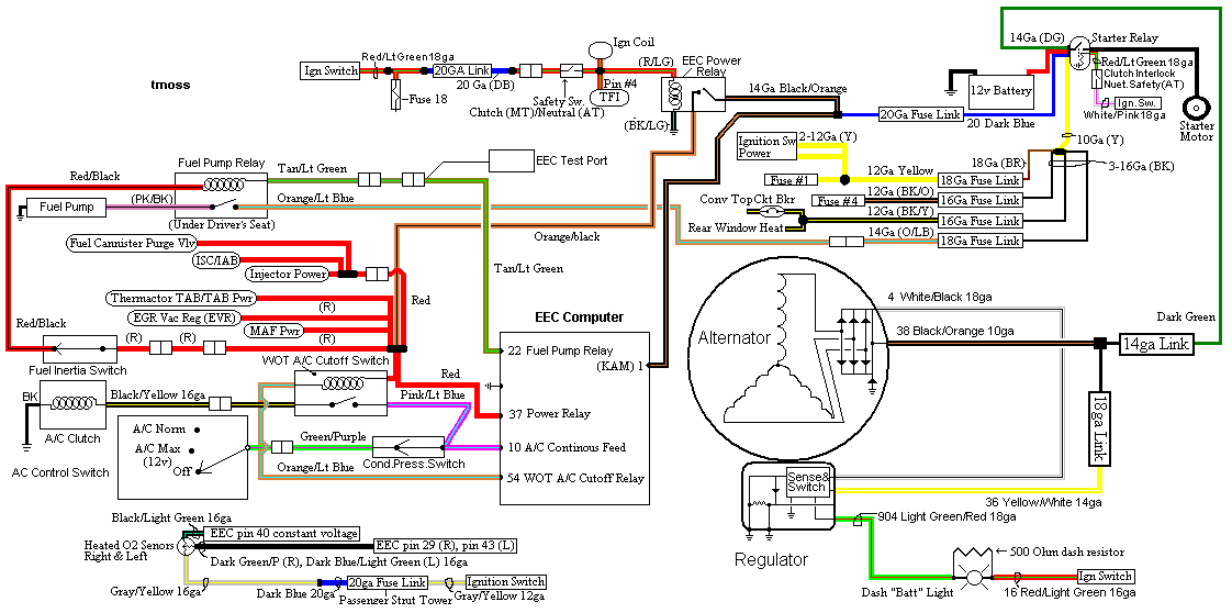
Diagrams courtesy of Tmoss & Stang&2birds
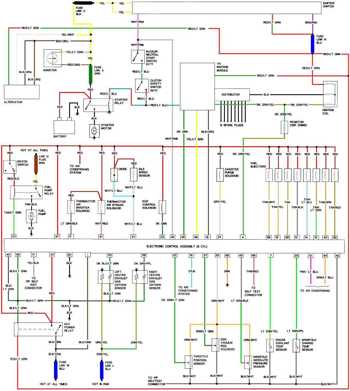
Mustang-86-Mustang-ECC-EFI.gif


See the following website for some help from Tmoss (diagram designer) & Stang&2Birds
(website host) for help on 86-95 5.0 Mustang wiring Mustang FAQ - Engine Information Everyone should bookmark this site.


Ignition switch wiring
http://www.veryuseful.com/mustang/tech/engine/images/IgnitionSwitchWiring.gif

Fuel, alternator, A/C and ignition wiring
http://www.veryuseful.com/mustang/tech/engine/images/fuel-alt-links-ign-ac.gif

Complete computer, actuator & sensor wiring diagram for 88-91 5.0 Mass Air Mustangs
http://www.veryuseful.com/mustang/tech/engine/images/88-91_5.0_EEC_Wiring_Diagram.gif

Complete computer, actuator & sensor wiring diagram for 91-93 5.0 Mass Air Mustangs
http://www.veryuseful.com/mustang/tech/engine/images/91-93_5.0_EEC_Wiring_Diagram.gif

Complete computer, actuator & sensor wiring diagram for 94-95 5.0 Mass Air Mustangs
http://www.veryuseful.com/mustang/tech/engine/images/94-95_5.0_EEC_Wiring_Diagram.gif

Vacuum diagram 89-93 Mustangs
http://www.veryuseful.com/mustang/tech/engine/images/mustangFoxFordVacuumDiagram.jpg

HVAC vacuum diagram
http://www.veryuseful.com/mustang/tech/engine/images/Mustang_AC_heat_vacuum_controls.gif

TFI module differences & pinout
http://www.veryuseful.com/mustang/tech/engine/images/TFI_5.0_comparison.gif

Fuse box layout
http://www.veryuseful.com/mustang/tech/engine/images/MustangFuseBox.gif

Code 22 or 126 MAP (vacuum) or BARO signal out of range. The MAP or BARO sensor is pretty much the same sensor for both Mass Air & Speed Density cars. The main difference is where it is connected. Mass Air cars vent it to the atmosphere, while Speed Density cars connect it to the intake manifold vacuum. Its purpose is to help set a baseline for the air/fuel mixture by sensing changes in barometric pressure. The MAP or BAP sensor puts out a 5 volt square wave that changes frequency with variations in atmospheric pressure. The base is 154 HZ at 29.92" of mercury - dry sunny day at sea level, about 68-72 degrees. You need an oscilloscope or frequency meter to measure it. There a very few DVM with a price tag under $40 that will measure frequency, but there are some out there.

The MAP/BARO sensor is mounted on the firewall behind the upper manifold on 86-93 Mustangs.

Baro or MAP test using frequency meter - run the test key on engine off. The noise from the ignition system will likely upset the frequency meter. I used a 10 x oscilloscope probe connected from the frequency meter to the MAP/BAP to reduce the jitter in the meter's readout.

If it is defective, your air/fuel ratio will be off and the car’s performance & emissions will suffer

Some basic checks you can make to be sure that the sensor is getting power & ground:
Note that all resistance tests must be done with power off. Measuring resistance with a circuit powered on will give false readings and possibly damage the meter.
Check the resistance between the black/white wire on the MAP/BARO sensor and then the black/white wire on the EGR and the same wire on the TPS. It should be less than 1 ohm. Next check the resistance between the black/white wire and the negative battery cable. It should be less than 1.5 ohm.

The following power on check requires you to turn the ignition switch to the Run position.
Use a DVM to check for 5 volts on the orange/white wire. If it is missing, look for +5 volts at the orange/white wire on the TPS or EGR sensors. Use the black/white wire for the ground for the DVM.

Code 29 - Vehicle Speed Sensor (VSS) is an electronic sender mounted on the speedo pickup gear on the trans. It works the cruse control for both 5 speed and auto trans cars. The VSS is used to tell the computer to speed up the idle as you slow to a stop. This helps keep the engine from stalling when you slow down for a stop sign or stop light.
Check to see if the electrical connector is plugged into it. Clean the connector & contacts with non flammable brake parts cleaner prior to replacing the sensor, as that may fix the problem. The sensor cost is under $30 and it is easy to replace.

Code 33 - Insufficient EGR flow detected.
Look for vacuum leaks, cracked vacuum lines, failed EGR vacuum regulator. Check to see if you have 10” of vacuum at the EGR vacuum connection coming from the intake manifold. Look for electrical signal at the vacuum regulator solenoid valves located on the rear of the passenger side wheel well. Using a test light across the electrical connector, it should flicker as the electrical signal flickers. Remember that the computer does not source any power, but provides the ground necessary to complete the circuit. That means one side of the circuit will always be hot, and the other side will go to ground or below 1 volt as the computer switches on that circuit.
Check for resistance between the brown/lt green wire on the EGR sensor and pin 27 on the computer: you should have less than 1.5 ohm.

See the following website for some help from Tmoss (diagram designer) & Stang&2Birds (website host)

http://www.veryuseful.com/mustang/tech/engine/images/fuel-alt-links-ign-ac.gif

http://www.veryuseful.com/mustang/tech/engine/images/88-91eecPinout.gif


EGR test procedure courtesy of cjones

to check the EGR valve:
bring the engine to normal temp.

connect a vacuum pump to the EGR Valve or see the EGR test jig drawing below. Connnect the test jig or to directly to manifold vacuum.

Do not connect the EGR test jig to the EVR (Electronic Vacuum Regulator).


apply 5in vacuum to the valve. Using the test jig, use your finger to vary the vacuum

if engine stumbled or died then EGR Valve and passage(there is a passageway through the heads and intake) are good.

if engine did NOT stumble or die then either the EGR Valve is bad and/or the passage is blocked.

if engine stumbled, connect EGR test jig to the hose coming off of the EGR Valve.
Use your finger to cap the open port on the vacuum tee.
snap throttle to 2500 RPM (remember snap the throttle don't hold it there).
did the vacuum gauge show about 2-5 in vacuum?
if not the EVR has failed

EGR test jig
attachment.php


The operation of the EGR vacuum regulator can be checked by using a test light applied across the wiring connector. Jumper the computer into self test mode and turn the key on but do not start the engine. You will hear all the actuators (including the EVR vacuum regulator) cycle. Watch for the light to flicker: that means the computer has signaled the EGR vacuum regulator successfully.

Code 63 - Throttle Position Sensor (TPS) signal too low.

Revised 02-Jul-2009 to update TPS setting procedure & add 10 pin connector layout.

Vref missing (5 volt reference voltage supplied by the computer), bad connections or damaged wiring, TPS sensor failed, TPS sensor way out of adjustment. Use a DVM to check for 5 volts on the Orange wire. If it is missing, look for +5 volts at the Orange wire on the EGR or MAP/Baro sensor located on the firewall near the center of the car. If there is +5 volts on the MAP/Baro sensor, but not on the EGR, clean the #2 & #5 pin on the white 10 pin connector. If there is +5 volts on the EGR but not on the TPS, look for bad wiring inside the engine fuel injector harness.

harness02.gif


Setting the TPS voltage
You'll need a Digital Voltmeter (DVM) to do the job.

Wire colors & functions:
Orange/white = 5 volt VREF from the computer
Dark Green/lt green = TPS output to computer
Black/white = Signal ground from computer

Always use the Dark Green/lt green & Black/white wires to set the TPS base voltage.

Do the test with the ignition switch in the Run position without the engine running.

Use the Orange/white & Black white wires to verify the TPS has the correct 5 volts source from the computer.
Setting the TPS: you'll need a good Digital Voltmeter (DVM) to do the job. Set the TPS voltage at .5- 1.1 range. Because of the variables involved with the tolerances of both computer and DVM, I would shoot for somewhere between .6 and 1.0 volts. Unless you have a Fluke or other high grade DVM, the second digit past the decimal point on cheap DVM’s is probably fantasy.

Since the computer zeros out the TPS voltage every time it powers up, playing with the settings isn't an effective aid to performance or drivability. The main purpose of checking the TPS is to make sure it isn't way out of range and causing problems.

The Orange/White wire is the VREF 5 volts from the computer. You use the Dark Green/Lt green wire (TPS signal) and the Black/White wire (TPS ground) to set the TPS. Use a pair of safety pins to probe the TPS connector from the rear of the connector. You may find it a little difficult to make a good connection, but keep trying. Put the safety pins in the Dark Green/Lt green wire and Black/White wire. Make sure the ignition switch is in the Run position but the engine isn't running.

Always adjust the TPS and Idle with the engine at operating temp. Dive it around for a bit if you can and get it nice and warm.

When you probe the leads of the TPS, do not use an engine ground, put the ground probe into the lead of the TPS. You should be connecting both meter probes to the TPS and not one to the TPS and the other to ground.

The TPS is a variable resistor, must like the volume control knob on a cheap radio. We have all heard them crackle and pop when the volume is adjusted. The TPS sensor has the same problem: wear on the resistor element makes places that create electrical noise. This electrical noise confuses the computer, because it expects to see a smooth increase or decrease as the throttle is opened or closed.

TPS testing: most of the time a failed TPS will set code 23 or 63, but not always. Use either an analog meter or a DVM with an analog bar graph and connect the leads as instructed above. Turn the ignition switch to the Run position, but do not start the engine. Note the voltage with the throttle closed. Slowly open the throttle and watch the voltage increase smoothly, slowly close the throttle and watch the voltage decrease smoothly. If the voltage jumps around and isn’t smooth, the TPS has some worn places in the resistor element. When the throttle is closed, make sure that the voltage is the same as what it was when you started. If it varies more than 10%, the TPS is suspect of being worn in the idle range of its travel.

Code 66 MAF below minimum test voltage.
Insufficient or no voltage from MAF. Dirty MAF element, bad MAF, bad MAF wiring, missing power to MAF. Check for missing +12 volts on this circuit. Check the two links for a wiring diagram to help you find the red wire for computer power relay switched +12 volts. Check for 12 volts between the red and black wires on the MAF heater (usually pins A & B). while the connector is plugged into the MAF. This may require the use of a couple of safety pins to probe the MAF connector from the back side of it.

There are three parts in a MAF: the heater, the sensor element and the amplifier. The heater heats the MAF sensor element causing the resistance to increase. The amplifier buffers the MAF output signal and has a resistor that is laser trimmed to provide an output range compatible with the computer's load tables.

If you have a K&N flat panel filter or other filter that requires oiling, excess oil may coat the MAF sensor element and cause problems.

The MAF element is secured by 2 screws & has 1 wiring connector. To clean the element, remove it from the MAF housing and spray it down with electronic parts cleaner or non-inflammable brake parts cleaner (same stuff in a bigger can and cheaper too).

Changes in RPM causes the airflow to increase or decease, changing the voltage output.. The increase of air across the MAF sensor element causes it to cool, allowing more voltage to pass and telling the computer to increase the fuel flow. A decrease in airflow causes the MAF sensor element to get warmer, decreasing the voltage and reducing the fuel flow. Measure the MAF output at pins C & D on the MAF connector (dark blue/orange and tan/light blue) or at pins 50 & 9 on the computer. Be sure to measure the sensor output by measuring across the pins and not between the pins and ground.

At idle = approximately .6 volt
20 MPH = approximately 1.10 volt
40 MPH = approximately 1.70 volt
60 MPH = approximately 2.10 volt

Check the resistance of the MAF signal wiring. Pin D on the MAF and pin 50 on the computer (dark blue/orange wire) should be less than 2 ohms. Pin C on the MAF and pin 9 on the computer (tan/light blue wire) should be less than 2 ohms.

There should be a minimum of 10K ohms between either pin C or D on the MAF wiring connector and ground. Make your measurement with the MAF disconnected from the wiring harness.


See the following website for some help from Tmoss (diagram designer) & Stang&2Birds (website host) for help on 88-95 wiring Mustang FAQ - Wiring & Engine Info

Ignition switch wiring
http://www.veryuseful.com/mustang/tech/engine/images/IgnitionSwitchWiring.gif

Fuel pump, alternator, ignition & A/C wiring
http://www.veryuseful.com/mustang/tech/engine/images/fuel-alt-links-ign-ac.gif

Computer,. actuator & sensor wiring
http://www.veryuseful.com/mustang/tech/engine/images/88-91_5.0_EEC_Wiring_Diagram.gif

Fuse panel layout
http://www.veryuseful.com/mustang/tech/engine/images/MustangFuseBox.gif

Vacuum routing
http://www.veryuseful.com/mustang/tech/engine/images/mustangFoxFordVacuumDiagram.jpg

Code 67 - clutch not depressed (5 speed) or car not in neutral or park (auto) or A/C in On position when codes
where dumped. Possible neutral safety switch or wiring problem. This code may prevent you from running the Key On
Engine On tests. You can generally ignore this code, since it has no effect on engine performance.

The computer wants to make sure the A/C is off due to the added load on the engine for the engine running tests. It also
checks to see that the transmission is in Neutral or the clutch depressed (T5, T56, Tremec 3550 & TKO). This prevents
the diagnostics from being run when the car is driven. Key On Engine Running test mode takes the throttle control away
from the driver for several tests. This could prove hazardous if the computer was jumpered into test mode and then driven.

The NSS code 67 can be bypassed for testing. You will need to temporarily ground computer pin 30 to the chassis.
Computer pin 30 uses a Lt blue/yellow wire. Remove the passenger side kick panel and then remove the plastic cover from
the computer wiring connector. Use a safety pin to probe the connector from the rear. Jumper the safety pin to the
ground near the computer.

Code 87 – fuel pump primary circuit failure. The fuel pump lost power while the engine was running. Check fuel pump relay, check inertia switch, wiring to/from inertia switch, red wire going to inertia switch for +12volts. Check the other side of inertia switch for +12 volts.

Diagram of the fuel pump wiring for 86-90 cars
attachment.php


Diagram of the fuel pump wiring for 91-93 cars.
attachment.php


Code 96 86-90 model Mustangs. KOEO- Fuel pump monitor circuit shows no power - Fuel pump relay or battery power feed was open - Power / Fuel Pump Circuits. The fuel pump lost power at some time while the ignition switch was in the run position.

Look for a failing fuel pump relay, bad connections or broken wiring. The fuel pump relay is located under the Mass Air Meter on Fox bodied stangs built after 91. On earlier model cars is under the passenger seat. On Mass Air Conversions, the signal lead that tells the computer that the fuel pump has power may not have been wired correctly. See Mustang Mass Air Conversion | StangNet

Diagram courtesy of Tmoss & Stang&2birds
fuel-alt-links-ign-ac.gif


Look for power at the fuel pump - the fuel pump has a connector at the rear of the car with a pink/black wire and a black wire that goes to the fuel pump. The pink/black wire should be hot when the test connector is jumpered to the test position. . To trick the fuel pump into running, find the ECC test connector and jump the connector in the lower RH corner to ground.
attachment.php


86-90 Models:
Using the diagram, check the red/black wire from the fuel pump relay: you should see 12 volts or so. If not, check the inertia switch: on a hatch it is on the drivers side by the taillight. Look for a black rubber plug that pops out: if you don't find it, then loosen up the plastic trim. Check for voltage on both sides of the switch. If there is voltage on both sides, then check the Pink/black wire on the fuel pump relay: it is the power feed to the fuel pump. Good voltage there, then the fuel pump is the likely culprit since it is getting power. No voltage there, check the Orange/Lt blue wire, it is the power feed to the fuel pump relay & has a fuse link in it. Good voltage there & at the Pink/black wire, swap the relay.

attachment.php


[