
You are using an out of date browser. It may not display this or other websites correctly.
You should upgrade or use an alternative browser.
You should upgrade or use an alternative browser.
Fox Fuel Pressure Problem
- Thread starter roworld
- Start date
-
Sponsors (?)
I rev it with the vacuum connected and the pressure increases. I also blew air through the fuel lines to make sure they were not cloged.
Micheal Nadeau
Active Member
Does the car misfire when the fuel pressure is lowered? Unplug each injector one at a time and see if the fuel pressure changes. It should increase since the injector is no longer spraying. See if unplugging all 8 make a difference.
What is the pressure with the vacuum disconnected from the regulator when it is idling? When vacuum is connected it will read higher based on how much vacuum is pulling on it. So find out what it's pressure is without vacuum and not revving it.
My pressure gauge reads around 55 psi with the vacuum off and 50 with the vacuum on. If I rev the car with the vacuum on the pressure does rise. I replaced the fuel pump last night with a walbro 255 and I still have the same problem. I just checked the code and this is what I got. Codes 31, 81, 82, 85, 41, 91, 96. Some of the codes are for the EGR system because its disconnected.
Have you adjusted the regulator all the way out? Is the lock nut on the adjustment screw tight or even there?
Yes it has a lock nut. Its not adjusted out all the way thats the lowest pressure that will keep the engine running.
Have you tried swapping out pressure gauges sometimes the bourdon tube inside them will become inaccurate over time
Since you posted the codes, lets look at them.
codes 31, 81,82,85 are emissions specific codes; they may be there because the equipment is missing or disabled. The emission equipment shuts off at full throttle, so they have every little effect on performance. The main concern is is that if you still have the catalytic converter H pipe, the 81 & 82 codes need to be fixed before you clog the cat converters.
Code 41 or 91. Or 43 Three digit code 172 or 176 - O2 sensor indicates system lean. Look for a vacuum leak or failing O2 sensor.
Revised 20-Jan-2014 to add code 43 to test collection
Code 41 is a RH side sensor, as viewed from the driver's seat.
Code 91 is the LH side sensor, as viewed from the driver's seat.
Code 172 is the RH side sensor, as viewed from the driver's seat.
Code 176 is the LH side sensor, as viewed from the driver's seat.
Code 43 is not side specific according to the Probst Ford Fuel injection book.
The computer sees a lean mixture signal coming from the O2 sensors and tries to compensate by adding more fuel. Many times the end result is an engine that runs pig rich and stinks of unburned fuel.
The following is a Quote from Charles O. Probst, Ford fuel Injection & Electronic Engine control:
"When the mixture is lean, the exhaust gas has oxygen, about the same amount as the ambient air. So the sensor will generate less than 400 Millivolts. Remember lean = less voltage.
When the mixture is rich, there's less oxygen in the exhaust than in the ambient air , so voltage is generated between the two sides of the tip. The voltage is greater than 600 millivolts. Remember rich = more voltage.
Here's a tip: the newer the sensor, the more the voltage changes, swinging from as low as 0.1 volt to as much as 0.9 volt. As an oxygen sensor ages, the voltage changes get smaller and slower - the voltage change lags behind the change in exhaust gas oxygen.
Because the oxygen sensor generates its own voltage, never apply voltage and never measure resistance of the sensor circuit. To measure voltage signals, use an analog voltmeter with a high input impedance, at least 10 megohms. Remember, a digital voltmeter will average a changing voltage." End Quote
Testing the O2 sensors 87-93 5.0 Mustangs
Measuring the O2 sensor voltage at the computer will give you a good idea of how well they are working. You'll have to pull the passenger side kick panel off to gain access to the computer connector. Remove the plastic wiring cover to get to the back side of the wiring. Use a safety pin or paper clip to probe the connections from the rear.
Disconnect the O2 sensor from the harness and use the body side O2 sensor harness as the starting point for testing. Do not measure the resistance of the O2 sensor , you may damage it. Resistance measurements for the O2 sensor harness are made with one meter lead on the O2 sensor harness and the other meter lead on the computer wire or pin for the O2 sensor.
Backside view of the computer wiring connector:

87-90 5.0 Mustangs:
Computer pin 43 Dark blue/Lt green – LH O2 sensor
Computer pin 29 Dark Green/Pink – RH O2 sensor
The computer pins are 29 (L\RH O2 with a dark green/pink wire) and 43 (LH O2 with a dark blue/pink wire). Use the ground next to the computer to ground the voltmeter. The O2 sensor voltage should switch between .2-.9 volt at idle.
91-93 5.0 Mustangs:
Computer pin 43 Red/Black – LH O2 sensor
Computer pin 29 Gray/Lt blue – RH O2 sensor
The computer pins are 29 (LH O2 with a Gray/Lt blue wire) and 43 (RH O2 with a Red/Black wire). Use the ground next to the computer to ground the voltmeter. The O2 sensor voltage should switch between .2-.9 volt at idle.
Testing the O2 sensors 94-95 5.0 Mustangs
Measuring the O2 sensor voltage at the computer will give you a good idea of how well they are working. You'll have to pull the passenger side kick panel off to gain access to the computer connector. Remove the plastic wiring cover to get to the back side of the wiring. Use a safety pin or paper clip to probe the connections from the rear. The computer pins are 29 (LH O2 with a red/black wire) and 27 (RH O2 with a gray/lt blue wire). Use pin 32 (gray/red wire) to ground the voltmeter. The O2 sensor voltage should switch between .2-.9 volt at idle.
Note that all resistance tests must be done with power off. Measuring resistance with a circuit powered on will give false readings and possibly damage the meter. Do not attempt to measure the resistance of the O2 sensors, it may damage them.
Testing the O2 sensor wiring harness
Most of the common multimeters have a resistance scale. Be sure the O2 sensors are disconnected and measure the resistance from the O2 sensor body harness to the pins on the computer. Using the Low Ohms range (usually 200 Ohms) you should see less than 1.5 Ohms.
87-90 5.0 Mustangs:
Computer pin 43 Dark blue/Lt green – LH O2 sensor
Computer pin 29 Dark Green/Pink – RH O2 sensor
Disconnect the connector from the O2 sensor and measure the resistance:
From the Dark blue/Lt green wire in the LH O2 sensor harness and the Dark blue/Lt green wire on the computer pin 43
From the Dark Green/Pink wire on the RH Os sensor harness and the Dark Green/Pink wire on the computer pin 29
91-93 5.0 Mustangs:
Computer pin 43 Red/Black – LH O2 sensor
Computer pin 29 Gray/Lt blue – RH O2 sensor
Disconnect the connector from the O2 sensor and measure the resistance:
From the Red/Black wire in the LH O2 sensor harness and the Red/Black wire on the computer pin 43
From the Dark Green/Pink Gray/Lt blue wire on the RH Os sensor harness and the Gray/Lt blue wire on the computer pin 29
94-95 5.0 Mustangs:
Computer pin 29 Red/Black – LH O2 sensor
Computer pin 27 Gray/Lt blue – RH O2 sensor
From the Red/Black wire in the LH O2 sensor harness and the Red/Black wire on the computer pin 29
From the Dark Green/Pink Gray/Lt blue wire on the RH Os sensor harness and the Gray/Lt blue wire on the computer pin 27
There is a connector between the body harness and the O2 sensor harness. Make sure the connectors are mated together, the contacts and wiring are not damaged and the contacts are clean and not coated with oil.
The O2 sensor ground (orange wire with a ring terminal on it) is in the wiring harness for the fuel injection wiring. I grounded mine to one of the intake manifold bolts
Make sure you have the proper 3 wire O2 sensors. Only the 4 cylinder cars used a 4 wire sensor, which is not compatible with the V8 wiring harness.
Replace the O2 sensors in pairs if replacement is indicated. If one is weak or bad, the other one probably isn't far behind.
Code 41 can also be due to carbon plugging the driver’s side Thermactor air crossover tube on the back of the engine. The tube fills up with carbon and does not pass air to the driver’s side head ports, Remove the tube and clean it out so that both sides get good airflow: this may be more difficult than it sounds. You need something like a mini rotor-rooter to do the job because of the curves in the tube. Something like the outer spiral jacket of a flexible push-pull cable may be the thing that does the trick.
If you get only code 41 and have changed the sensor, look for vacuum leaks. This is especially true if you are having idle problems. The small plastic tubing is very brittle after many years of the heating it receives. Replace the tubing and check the PVC and the hoses connected to it.
Code 96 for 86-90 model 5.0 Mustang – KOEO- Fuel pump monitor circuit shows no power - Fuel pump relay or battery power feed was open - Power / Fuel Pump Circuits. The fuel pump lost power at some time while the ignition switch was in the run position. The main power feed to the pump is what is losing power.
Look for a failing fuel pump relay, bad connections or broken wiring. The fuel pump relay is located under the passenger seat. On Mass Air Conversions, the signal lead that tells the computer that the fuel pump has power may not have been wired correctly.
See http://www.stangnet.com/tech/maf/massairconversion.html

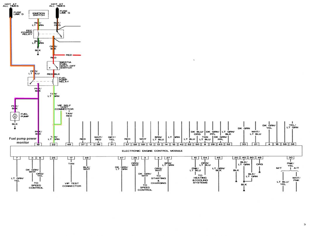
Look for power at the fuel pump - the fuel pump has a connector at the rear of the car with a pink/black wire and a black wire that goes to the fuel pump. The pink/black wire should be hot when the test connector is jumpered to the test position. . To trick the fuel pump into running, find the ECC test connector and jump the connector in the lower RH corner to ground.
86-90 Models:
Using the diagram, check the red/black wire from the fuel pump relay: you should see 12 volts or so. If not, check the inertia switch: on a hatch it is on the drivers side by the taillight. Look for a black rubber plug that pops out: if you don't find it, then loosen up the plastic trim. Check for voltage on both sides of the switch. If there is voltage on both sides, then check the Pink/black wire on the fuel pump relay: it is the power feed to the fuel pump. Good voltage there, then the fuel pump body to tank wiring harness connector is the likely culprit since it is getting power. No voltage there, check the Orange/Lt blue wire, it is the power feed to the fuel pump relay & has a fuse link in it. Good voltage there & at the Pink/black wire, swap the relay.
Keep in mind that the relay wiring and socket can also cause intermittent problems. Clean the relay socket with non-flammable brake parts cleaner or electrical contact cleaner. If you find damaged wiring at the relay socket, replacement pigtail socket assemblies are available at the auto parts stores. Be sure to solder the wires and cover the solder joints with heat shrink tubing if you replace the relay socket.
codes 31, 81,82,85 are emissions specific codes; they may be there because the equipment is missing or disabled. The emission equipment shuts off at full throttle, so they have every little effect on performance. The main concern is is that if you still have the catalytic converter H pipe, the 81 & 82 codes need to be fixed before you clog the cat converters.
Code 41 or 91. Or 43 Three digit code 172 or 176 - O2 sensor indicates system lean. Look for a vacuum leak or failing O2 sensor.
Revised 20-Jan-2014 to add code 43 to test collection
Code 41 is a RH side sensor, as viewed from the driver's seat.
Code 91 is the LH side sensor, as viewed from the driver's seat.
Code 172 is the RH side sensor, as viewed from the driver's seat.
Code 176 is the LH side sensor, as viewed from the driver's seat.
Code 43 is not side specific according to the Probst Ford Fuel injection book.
The computer sees a lean mixture signal coming from the O2 sensors and tries to compensate by adding more fuel. Many times the end result is an engine that runs pig rich and stinks of unburned fuel.
The following is a Quote from Charles O. Probst, Ford fuel Injection & Electronic Engine control:
"When the mixture is lean, the exhaust gas has oxygen, about the same amount as the ambient air. So the sensor will generate less than 400 Millivolts. Remember lean = less voltage.
When the mixture is rich, there's less oxygen in the exhaust than in the ambient air , so voltage is generated between the two sides of the tip. The voltage is greater than 600 millivolts. Remember rich = more voltage.
Here's a tip: the newer the sensor, the more the voltage changes, swinging from as low as 0.1 volt to as much as 0.9 volt. As an oxygen sensor ages, the voltage changes get smaller and slower - the voltage change lags behind the change in exhaust gas oxygen.
Because the oxygen sensor generates its own voltage, never apply voltage and never measure resistance of the sensor circuit. To measure voltage signals, use an analog voltmeter with a high input impedance, at least 10 megohms. Remember, a digital voltmeter will average a changing voltage." End Quote
Testing the O2 sensors 87-93 5.0 Mustangs
Measuring the O2 sensor voltage at the computer will give you a good idea of how well they are working. You'll have to pull the passenger side kick panel off to gain access to the computer connector. Remove the plastic wiring cover to get to the back side of the wiring. Use a safety pin or paper clip to probe the connections from the rear.
Disconnect the O2 sensor from the harness and use the body side O2 sensor harness as the starting point for testing. Do not measure the resistance of the O2 sensor , you may damage it. Resistance measurements for the O2 sensor harness are made with one meter lead on the O2 sensor harness and the other meter lead on the computer wire or pin for the O2 sensor.
Backside view of the computer wiring connector:
87-90 5.0 Mustangs:
Computer pin 43 Dark blue/Lt green – LH O2 sensor
Computer pin 29 Dark Green/Pink – RH O2 sensor
The computer pins are 29 (L\RH O2 with a dark green/pink wire) and 43 (LH O2 with a dark blue/pink wire). Use the ground next to the computer to ground the voltmeter. The O2 sensor voltage should switch between .2-.9 volt at idle.
91-93 5.0 Mustangs:
Computer pin 43 Red/Black – LH O2 sensor
Computer pin 29 Gray/Lt blue – RH O2 sensor
The computer pins are 29 (LH O2 with a Gray/Lt blue wire) and 43 (RH O2 with a Red/Black wire). Use the ground next to the computer to ground the voltmeter. The O2 sensor voltage should switch between .2-.9 volt at idle.
Testing the O2 sensors 94-95 5.0 Mustangs
Measuring the O2 sensor voltage at the computer will give you a good idea of how well they are working. You'll have to pull the passenger side kick panel off to gain access to the computer connector. Remove the plastic wiring cover to get to the back side of the wiring. Use a safety pin or paper clip to probe the connections from the rear. The computer pins are 29 (LH O2 with a red/black wire) and 27 (RH O2 with a gray/lt blue wire). Use pin 32 (gray/red wire) to ground the voltmeter. The O2 sensor voltage should switch between .2-.9 volt at idle.
Note that all resistance tests must be done with power off. Measuring resistance with a circuit powered on will give false readings and possibly damage the meter. Do not attempt to measure the resistance of the O2 sensors, it may damage them.
Testing the O2 sensor wiring harness
Most of the common multimeters have a resistance scale. Be sure the O2 sensors are disconnected and measure the resistance from the O2 sensor body harness to the pins on the computer. Using the Low Ohms range (usually 200 Ohms) you should see less than 1.5 Ohms.
87-90 5.0 Mustangs:
Computer pin 43 Dark blue/Lt green – LH O2 sensor
Computer pin 29 Dark Green/Pink – RH O2 sensor
Disconnect the connector from the O2 sensor and measure the resistance:
From the Dark blue/Lt green wire in the LH O2 sensor harness and the Dark blue/Lt green wire on the computer pin 43
From the Dark Green/Pink wire on the RH Os sensor harness and the Dark Green/Pink wire on the computer pin 29
91-93 5.0 Mustangs:
Computer pin 43 Red/Black – LH O2 sensor
Computer pin 29 Gray/Lt blue – RH O2 sensor
Disconnect the connector from the O2 sensor and measure the resistance:
From the Red/Black wire in the LH O2 sensor harness and the Red/Black wire on the computer pin 43
From the Dark Green/Pink Gray/Lt blue wire on the RH Os sensor harness and the Gray/Lt blue wire on the computer pin 29
94-95 5.0 Mustangs:
Computer pin 29 Red/Black – LH O2 sensor
Computer pin 27 Gray/Lt blue – RH O2 sensor
From the Red/Black wire in the LH O2 sensor harness and the Red/Black wire on the computer pin 29
From the Dark Green/Pink Gray/Lt blue wire on the RH Os sensor harness and the Gray/Lt blue wire on the computer pin 27
There is a connector between the body harness and the O2 sensor harness. Make sure the connectors are mated together, the contacts and wiring are not damaged and the contacts are clean and not coated with oil.
The O2 sensor ground (orange wire with a ring terminal on it) is in the wiring harness for the fuel injection wiring. I grounded mine to one of the intake manifold bolts
Make sure you have the proper 3 wire O2 sensors. Only the 4 cylinder cars used a 4 wire sensor, which is not compatible with the V8 wiring harness.
Replace the O2 sensors in pairs if replacement is indicated. If one is weak or bad, the other one probably isn't far behind.
Code 41 can also be due to carbon plugging the driver’s side Thermactor air crossover tube on the back of the engine. The tube fills up with carbon and does not pass air to the driver’s side head ports, Remove the tube and clean it out so that both sides get good airflow: this may be more difficult than it sounds. You need something like a mini rotor-rooter to do the job because of the curves in the tube. Something like the outer spiral jacket of a flexible push-pull cable may be the thing that does the trick.
If you get only code 41 and have changed the sensor, look for vacuum leaks. This is especially true if you are having idle problems. The small plastic tubing is very brittle after many years of the heating it receives. Replace the tubing and check the PVC and the hoses connected to it.
Code 96 for 86-90 model 5.0 Mustang – KOEO- Fuel pump monitor circuit shows no power - Fuel pump relay or battery power feed was open - Power / Fuel Pump Circuits. The fuel pump lost power at some time while the ignition switch was in the run position. The main power feed to the pump is what is losing power.
Look for a failing fuel pump relay, bad connections or broken wiring. The fuel pump relay is located under the passenger seat. On Mass Air Conversions, the signal lead that tells the computer that the fuel pump has power may not have been wired correctly.
See http://www.stangnet.com/tech/maf/massairconversion.html
Look for power at the fuel pump - the fuel pump has a connector at the rear of the car with a pink/black wire and a black wire that goes to the fuel pump. The pink/black wire should be hot when the test connector is jumpered to the test position. . To trick the fuel pump into running, find the ECC test connector and jump the connector in the lower RH corner to ground.
86-90 Models:
Using the diagram, check the red/black wire from the fuel pump relay: you should see 12 volts or so. If not, check the inertia switch: on a hatch it is on the drivers side by the taillight. Look for a black rubber plug that pops out: if you don't find it, then loosen up the plastic trim. Check for voltage on both sides of the switch. If there is voltage on both sides, then check the Pink/black wire on the fuel pump relay: it is the power feed to the fuel pump. Good voltage there, then the fuel pump body to tank wiring harness connector is the likely culprit since it is getting power. No voltage there, check the Orange/Lt blue wire, it is the power feed to the fuel pump relay & has a fuse link in it. Good voltage there & at the Pink/black wire, swap the relay.
Keep in mind that the relay wiring and socket can also cause intermittent problems. Clean the relay socket with non-flammable brake parts cleaner or electrical contact cleaner. If you find damaged wiring at the relay socket, replacement pigtail socket assemblies are available at the auto parts stores. Be sure to solder the wires and cover the solder joints with heat shrink tubing if you replace the relay socket.
Similar threads
- Replies
- 27
- Views
- 2K
- Replies
- 3
- Views
- 312
- Replies
- 27
- Views
- 2K
- Replies
- 4
- Views
- 2K