Computer And Engine Issues

I read the stickies, and I searched, but couldn't find an exact match for my problem. Well, the cars problem. There is no fixing mine ;)

1991 5.0 LX AOD.
Supposedly rebuilt 306.
130k miles; less if it really was rebuilt.
Supposed E303 cam (sounds stock to me).
Trick Flow Street Burner intake.
70mm TB, 75mm MAF cal'ed to stock injectors.
Compression & leak down test good all cyls. O/R 2.5" Xpipe into Flowmaster 2 chambers, dumps.
4.10 gears.

EVERYTHING ELSE IS STOCK.

1: the car smells like gas, like it runs rich. I know it will without cats, but it shouldn't be burning my eyes outside the car. I do suspect that i have at least one leaky injector; the fuel pressure goes away about 10 minutes after shut off. Could this be a tuning issue, if it wasn't tuned with the bigger intake? I seem to remember these computers (A9L and A9P) being pretty adaptive to mild mods. But if the engine was bored, would it change the VE a bit, and possibly be too much for the stock tune?

2: it burns oil (about a quart every two weeks with lots of town and highway driving). Not when I start it (not valve guides), but if I drop the hammer, I see a light cloud of blue smoke. And my wife has told me it smells really strong following me when I do that. So if its not valve guides, and the leak test indicates good piston rings, could it be the PCV system? Is there a better fix than that chinsy little valve behind the intake?

3: no CEL, no flashes and no communication with the scanner when I try to run self-tests. Indicator light is good-it comes on if I ground the STO pin on the connector. But apparently the computer is not grounding it. It never comes on. Some have accidentally connected 12V to the signal common, and friend the SIG RTN trace inside the computer. I opened the computer and saw no evidence of this. The three electrolytic capacitors are bad (two 47uF 16V and one 10uF 64V). They are leaking. I'm going to replace them, but not having a schematic of the computer, I don't know if they have anything to do with this problem. Any ideas? And could this be affecting #1?


Sorry for such a long post, but I'd rather give too much info than not enough. Thanks in advance.
 
  • Sponsors (?)


Here's your answer for why the computer won't dump codes and the car runs poorly....


Computer will not go into diagnostic mode on 91-95 model 5.0 Mustangs

Revised 7-June-2014 to change resistance figures to wiring checks

How it is supposed to work:
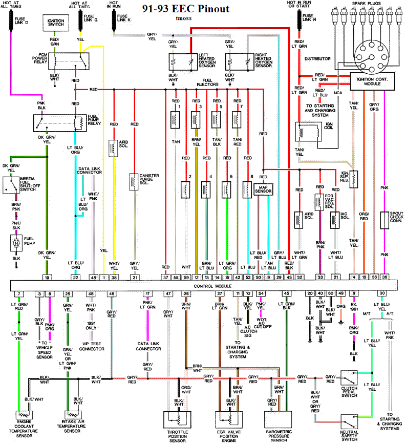
The grey/red wire (pin 46) is signal ground for the computer. It provides a dedicated ground for the EGR, Baro, ACT, ECT, & TPS sensors as well as the ground to put the computer into self-test mode. If this ground is bad, none of the sensors mentioned will work properly. That will severely affect the car's performance. You will have hard starting, low power and drivability problems. Since it is a dedicated ground, it passes through the computer on its way to the computer main power ground that terminates at the battery pigtail ground. It should read less than 1 ohm when measured from anyplace on the engine harness with the battery pigtail ground as the other reference point for the ohmmeter probe.

What sometimes happens is that the test connector grey/red wire gets jumpered to power which either burns up the wiring or burns the trace off the pc board inside the computer. That trace connects pins 46 to pins 40 & 60.

The STI (Self Test Input ) is jumpered to ground to put the computer into test mode. Jumpering it to power can produce unknown results, including damage to the computer. The ohm test simply verifies that there are no breaks in the wiring between the test connector and the computer input.

How to test the wiring :
With the power off, measure the resistance between the computer test ground (grey/red wire) on the self- test connector and battery ground. You should see less than 1 ohm.

attachment.php


If that check fails, remove the passenger side kick panel and disconnect the computer connector. There is a 10 MM bolt that holds it in place. Measure the resistance between the grey/red wire and pin 46 on the computer wiring connector: it should be less than 1 ohm. More than 1 ohm is a wiring problem. If it reads 1 ohm or less, then the computer is suspect. On the computer, measure the resistance between pin 46 and pins 40 & 60: it should be less than 1 ohm. More than that and the computer’s internal ground has failed, and the computer needs to be repaired or replaced.

See Computer issue? | Mustang Forums at StangNet for Joel5.0’s fix for the computer internal signal ground.

If the first ground check was good, there are other wires to check. Measure the resistance between the STI computer self-test connector (red/white wire) and pin 48 on the computer main connector: it should be less than 1.5 ohms. More than 1 ohms is a wiring problem

The following is a view from the computer side of the computer wiring connector: it is for an A9L, A9P computer.
eec-iv-computer-connector-for-5-0-mustang-gif.88243


a9x-series-computer-connector-wire-side-view-gif.71316


Diagram courtesy of Tmoss & Stang&2birds

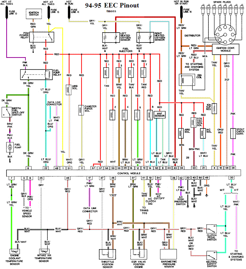
Check out the diagram and notice all the places the grey/red wire goes. Almost every sensor on the engine except the MAF is connected to it.

91-93 5.0 Mustangs
91-93_5.0_EEC_Wiring_Diagram.gif


Complete computer, actuator & sensor wiring diagram for 94-95 Mass Air Mustangs
94-95_5.0_EEC_Wiring_Diagram.gif


See the graphic for the 10 pin connector circuit layout.
salt-pepper-10-pin-connectors-65-jpg.68512


See the following website for some help from Tmoss (diagram designer) & Stang&2Birds
(website host) for help on 88-95 wiring Mustang FAQ - Wiring & Engine Info
 
Thanks for the info! I did check the circuits for continuity, but you mentioned a couple I didn't do.

Of note, I saw no signs of damage on the computer, and the car runs good, except for the fumes. I'll do some more snooping tomorrow and post up what I find. Thanks again!

Edit: I forgot to mention that I was trying to check the timing, and it seemed like removing the spout connector didn't affect timing. I'm gonna look at that tomorrow also...
 
Update: still need to do a couple wiring checks, but I did see the problem with the timing. Previous owner had it at 28 deg initial!!! And I've been running 87 octane! So when I pulled the spout connector, it went from 30 to 28, and I didn't catch it. I set it at 12, that may make a difference in the fumes. Well see.
 
OK, had some time to mess with it today. Here is what I found:
My car (VIN says it's a '91) has some different colors than what these diagrams have, but the pinouts are the same. That same diagram on alldata doesn't designate wire colors; maybe that's why.

1) SIGRTN to ground is good.
2) STI from test conn. to computer is good.
3) STO/MIL (CEL) from test conn. to computer is good.
4) Pins 46, 40 and 60 on the computer all have continuity.
5) The SIGRTN trace on the computer is intact.
6) Battery positive from fuse box to test conn. is good.
7) Grounding STO at the test conn will illuminate the CEL, GROUNDING IT AT THE COMPUTER WILL NOT.
8) I did replace the caps and verified the car still runs. Even though you know what you're doing, do you also get a little puckered before you turn the key after a repair? I sure do.

So, either the computer has decided not to run diagnostics any more, a transistor has failed and won't ground the STO signal, or possibly the STO wire is bad between the computer and the CEL. That's the only reason I can think of for #7 above.

I think I'm gonna disconnect the MAF to induce a fault, and check PIN 17 while it's running. I've never had the need for a breakout box on a car before, but I may just make one since I'm never getting rid of this one...
 
Update:

I probed pin 17 at the computer (STO, CEL) and in start and run, it maintains battery voltage, like it's supposed to. When I initiate the self-test via the jumper, I believe the computer runs it because you can hear the clicks and hum of the computer doing stuff.

However, the computer never grounds STO to illuminate the CEL. I believe there is a simple defective transistor that's not switching to do this. Problem is, theres no way of knowing which one it is without a schematic.

Does anyone know where I can find a schematic of the internals to the computer?
 
So I was right about the transistor. It took hours for me to find this schematic, but here it is. In the lower right corner (colored in red) is pin 17, hot in start and run. If you follow it back, you see the transistor (Q10). I did draw the circle around it, because transistors are supposed to have a circle in an electronic schematic.

Think of a transistor as a relay, turned on remotely to allow a higher current to pass through. In this case, the remote (bias) is in blue, and you can see it leads to a multiplexer (kinda like a hub for input/output computer signals), and all the way to the processor itself. So when the processor wants to output codes or turn on the CEL, it sends a small voltage out through the mux, to Q10. This would be like the voltage to the coil on a relay. This causes Q10 to "turn on" or conduct current, providing a current path for the battery voltage from pin 17 to ground, illuminating the CEL.

I verified that the processor is commanding Q10 on via a bias voltage, but Q10 is not responding, and so the CEL doesn't light up. Transistors, unlike capacitors, don't show signs of malfunctioning, unless they have been subjected to a very high current. This one appears to be fine on the outside. When I find a replacement and repair it (these are obsolete, I'll have to find suitable replacement), I will post a couple more pics.

Thanks for all your help!

17318353075_1af13ea1f8_o.jpg EEC-schematicpaint