Electrical 91 Lx - Factory Tachometer Issues

I've driven the car several times today and so far so good.
Seems to be fixed.
Glad to hear that. Just keep watching and let us know how it goes. The tach "NOS I got off of Ebay " was that a stock type replacement or an externally mounted tach?
If it was a stock type replacement, please post the details so that some of the other guys with tach problems have a source other than the J/Y.
 
  • Sponsors (?)


Thanks, I'm glad too. Things like that drive me crazy until I fix them.
It is a stock replacement. I prefer to keep certain things like that stock versus after market.
I never have been a fan of the externally mounted tach.
Details for the NOS tach are below.

1990-1993 Mustang NOS V8 5.0 Tachometer Tach RPM Gauge F2ZZ-17360-B
The guys ebay store is blueovalindustries

http://www.ebay.com/itm/231196308305?ssPageName=STRK:MEWNX:IT&_trksid=p3984.m1439.l2649
 
I also recently bought on of these tachs to go back to stock after removing my white faced Saleen gauges. I have had nothing but trouble from this seller (I haven't installed the tach yet) - just an FYI - research this sellers feedback and decide whether or not you want to take a chance...

All kinds of excellent troubleshooting info here! Subscribing to this thead for future reference!

OP - I Hope your gremlins have been finally put to rest!

Man I'm sorry to hear that. I didn't have any issues dealing with him. Shipped out and arrived very quickly. It's been working great with no issues so far (knock on wood). Good luck...
 
Sorry for bringing this old post back to life. What if I have pulled the cover off of the wires at the ICM module all the way to the intake and didn't see anything but wires?
No resistor looking thing anywhere in that loom.

I have a 1990 Mustang LX 5.0 Notch, 5 spd with a Trickflow TW top end.
 
Last edited by a moderator:
Sorry for bringing this old post back to life. What if I have pulled the cover off of the wires at the ICM module all the way to the intake and didn't see anything but wires?
No resistor looking thing anywhere in that loom.

I have a 1990 Mustang LX 5.0 Notch, 5 spd with a Trickflow TW top end.

Resistor location: A big thanks to liljoe07 for this information:

Check over by the brake booster. Its not in the harness on the TFI, its on the main part of the harness over by the plugs that connect to the dash harness. About 6" or so from that, going back toward the EEC.

If I remember right, the resistor is covered in a shrink tubing that is sealed to the wires. So, you wont be able see any markings. The shrink tubing is labeled though. It's a 22kohm 1/2 watt resistor.

Here is the location.

20150328_105525-jpg.532446
 

Attachments

  • 488635-a2077ca036da351b22cffc99f37d5dee.jpg
    488635-a2077ca036da351b22cffc99f37d5dee.jpg
    6.8 KB · Views: 154
Last edited:
Thanks, I will look for the resistor later today. It's already hot enough outside here in Texas.

jrichker, I'm having the annoying engine stumble that has been aired on these forums previously.
My issue is simply at a constant RPM between 1000-2000 rpms, whether the engine is cold or hot.
I have my timing set at 10 degrees BTDC without the spout connected, when it's connected the
timing does advance to 14 degrees BTDC. I have replaced the entire distributor (which had the PiP
and ICM installed in it) and it didn't alleviate anything so I removed the new distributor and replaced
the PiP and ICM with FOMOCO parts this too did not help.
The motor is fresh, it's a 302 bored .40 over without forged pistons. I'm not running a turbo or a screw.
The top end of the motor is: Trick Flow Mustang Top End Kit, w/ Street Burner Intake Black (87-93) 5.0L
I have ran codes on the car recently: 94, 44, 34 and 18, The first 3 are understandable as there is no
longer any emission devices on the car but the code 18 is very elusive at the moment.
The tps is set at .94 VDC (KOEO), the PiP sensor is: flashing (dist. to pos. battery term.) 8.05-8.1 VDC
flashing (dist. to neg. battery term.) 6.2-6.3 VDC.
I have performed cylinder balance tests and they pass everytime. I have performed the resistance test
from the ICM to the ECU connector and have found them to be as described, spout to ECU pin #36 is .8
ohms and the ECU pin #36 to body ground is zero ohms. The car idles relatively smooth and runs great
with my foot in it but it's very annoying at constant speed as the car bucks a little......just enough to make
me want to set the car on fire and be done with it.

Help, me Obi Wan Kenobi....you're my only hope
 
The code 18 is the key...again...

Code 18 - SPOUT out or wiring fault - look for short to ground in SPOUT wiring going back to the computer. Possible bad TFI or defective 22 K resistor in the IDM wiring

Use a timing light to check the timing: remove the SPOUT and observe that the timing retards at least 4 degrees. Put the SPOUT back in place and observe that the spark advances at least 4 degrees.
This code can disable spark advance and reduce power and fuel economy.

Remove the passenger side kick panel and disconnect the computer connector.
There is a 10 MM bolt that holds it in place.
Disconnect the TFI module connector from the TFI and the measure the resistance between the yellow/lt green wire and ground.
You should see greater than 100 K (100000) ohms.
Check the resistance from Pin 4 on the computer connector (dark green/yellow) and the dark green/yellow wire on the TFI connector. You should see 20-24 K Ohms (20,000-24,0000 ohms).


Resistor location: A big thanks to liljoe07 for this information:

Check over by the brake booster. Its not in the harness on the TFI, its on the main part of the harness over by the plugs that connect to the dash harness. About 6" or so from that, going back toward the EEC.

If I remember right, the resistor is covered in a shrink tubing that is sealed to the wires. So, you wont be able see any markings. The shrink tubing is labeled though. It's a 22kohm 1/2 watt resistor.

Here is the location.

20150328_105525-jpg.532446


Next measure the resistance between the yellow/lt green wire on the TFI module connector and Pin 36 on the computer connector. With the SPOUT plug in place, you should see less than 2 ohms.

The following is a view from the computer side of the computer connector.
eec-iv-computer-connector-for-5-0-mustang-gif.88243


This diagram is the wire side of the computer connector.
a9x-series-computer-connector-wire-side-view-gif.71316


Diagram courtesy of Tmoss & Stang&2birds

88-91_5.0_EEC_Wiring_Diagram.gif
 
First off some of the wire coloring in the wiring diagram is not the same color of the wiring in my car
but the locations and wiring color are the same on the TFI and ECU plugs. Where the diagram shows
pin #16 wiring to be black/orange mine is orange/red, pin #4 wiring is dark green/yellow mine is brown/
yellow. All the other wiring is correctly identified for the TFI module on the diagram.

OK, here's the test results from things you mentioned I should check.

1. The yellow/light green wire at the TFI connector to a body ground was 119k ohms.
2. The dark green/yellow (actual brown/yellow) at the TFI connector to pin #4 on the computer
connector was 21.6k ohms.
3. The yellow/light green wire at the TFI connector to pin# 36 on the computer connector (with the spout
plugged in) was .85 ohms.

In my problematic post I mentioned that the timing did advance after base timing was set at 10 degrees
BTDC, it advances at least 4 degrees. Removing the spout connector will make the timing retard 4 degrees.

Thanks
 
Last edited:
Could the barometric pressure sensor cause any engine stumbling issues? The sensor on my car seems to be original, it's one of the few items I haven't replaced.
Have you done the electrical checks on the SPOUT wiring yet?
If not, do them BEFORE you try anything else.

Don't throw parts at a problem. If the MAP/Baro senor is bad, it should set code 22.

MAP/BARO sensor operation and code 22

Revised 14-Nov-2014 to add wire colors for frequency & voltage testing and engine sensor wiring diagrams.

On a Speed Density car, the MAP/BARO sensor is connected to the intake manifold and acts to sense the manifold pressure. Lower vacuum inside the intake manifold when combined with more throttle opening measured by the TPS means more airflow through the engine. As airflow increases, fuel flow through the injectors needs to increase to keep the air/fuel ratio where it needs to be. When manifold vacuum increases, the engine is either decelerating or idling, and it needs to reduce the fuel flow through the injectors.

On a Mass Air car, the MAP/BARO sensor vents to open air and actually senses the barometric pressure due to changes in weather and altitude. Its purpose is to set a baseline for the computer to know the barometric pressure. As barometric pressure decreases, it leans out the fuel flow to compensate for less oxygen in the air. When the barometric pressure rises, it increases to add fuel since there is more oxygen in the air. The fuel requirements decrease as altitude increases, since the atmospheric pressure decreases.

Disconnecting the MAP or BARO sensor will set code 22.

Misconnecting the BARO sensor to vacuum on a Mass Air car will cause the computer to lean out the fuel mixture.

Code 22 or 126 MAP (vacuum) or BARO signal out of range. The MAP or BARO sensor is pretty much the same sensor for both Mass Air & Speed Density cars. The main difference is where it is connected. Mass Air cars vent it to the atmosphere, while Speed Density cars connect it to the intake manifold vacuum. Its purpose is to help set a baseline for the air/fuel mixture by sensing changes in barometric pressure. The MAP or BAP sensor puts out a 5 volt square wave that changes frequency with variations in atmospheric pressure. The base is 154 HZ at 29.92" of mercury - dry sunny day at sea level, about 68-72 degrees. You need an oscilloscope or frequency meter to measure it. There a very few DVM’s with a price tag under $40 that will measure frequency, but there are some out there.

Map sensor wiring:
black/white - ground
orange/white or +5 volts power
white/red signal out.

Measure the +5 volt supply using the orange/white and black/white wires
Measure the signal using the black/white and white/red wires.

The MAP/BARO sensor is mounted on the firewall behind the upper manifold on 86-93 Mustangs.

Baro or MAP test using a real frequency meter - run the test key on, engine off. The noise from the ignition system will likely upset the frequency meter. I used a 10 x oscilloscope probe connected from the frequency meter to the MAP/BAP to reduce the jitter in the meter's readout. And oscilloscope is very useful if you have access to one or know of someone who does. With an oscilloscope, you can see the waveform and amplitude.

If it is defective, your air/fuel ratio will be off and the car’s performance & emissions will suffer

Some basic checks you can make to be sure that the sensor is getting power & ground:
Note that all resistance tests must be done with power off. Measuring resistance with a circuit powered on will give false readings and possibly damage the meter.
Check the resistance between the black/white wire on the MAP/BARO sensor and then the black/white wire on the EGR and the same wire on the TPS. It should be less than 1 ohm. Next check the resistance between the black/white wire and the negative battery cable. It should be less than 1.5 ohm.

The following power on check requires you to turn the ignition switch to the Run position.
Use a DVM to check for 5 volts on the orange/white wire. If it is missing, look for +5 volts at the orange/white wire on the TPS or EGR sensors. Use the black/white wire for the ground for the DVM.

a9x-series-computer-connector-wire-side-view-gif.71316


eec-iv-computer-connector-for-5-0-mustang-gif.88243


Diagrams courtesy of Tmoss & Stang&2birds

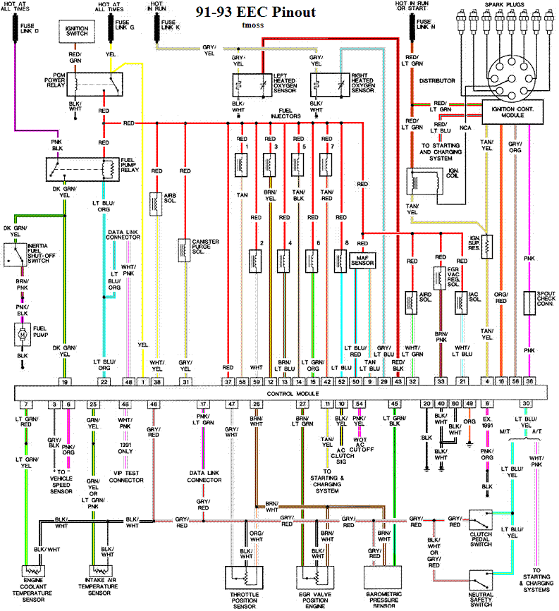
Complete computer, actuator & sensor wiring diagram for 88-91 Mass Air Mustangs
88-91_5.0_EEC_Wiring_Diagram.gif


Complete computer, actuator & sensor wiring diagram for 91-93 Mass Air Mustangs
91-93_5.0_EEC_Wiring_Diagram.gif


See the following website for some help from Tmoss (diagram designer) & Stang&2Birds (website host) for help on 88-95 wiring Mustang FAQ - Wiring & Engine Info Everyone should bookmark this site.

Complete computer, actuator & sensor wiring diagram for 91-93 Mass Air Mustangs
http://www.veryuseful.com/mustang/tech/engine/images/91-93_5.0_EEC_Wiring_Diagram.gif

Complete computer, actuator & sensor wiring diagram for 88-91 Mass Air Mustangs
http://www.veryuseful.com/mustang/tech/engine/images/88-91_5.0_EEC_Wiring_Diagram.gif

Ignition switch wiring
http://www.veryuseful.com/mustang/tech/engine/images/IgnitionSwitchWiring.gif

Fuel, alternator, A/C and ignition wiring
http://www.veryuseful.com/mustang/tech/engine/images/fuel-alt-links-ign-ac.gif

O2 sensor wiring harness
http://www.veryuseful.com/mustang/tech/engine/images/mustangO2Harness.gif

Vacuum diagram 89-93 Mustangs
http://www.veryuseful.com/mustang/tech/engine/images/mustangFoxFordVacuumDiagram.jpg

HVAC vacuum diagram
http://www.veryuseful.com/mustang/tech/engine/images/Mustang_AC_heat_vacuum_controls.gif

TFI module differences & pin out
http://www.veryuseful.com/mustang/tech/engine/images/TFI_5.0_comparison.gif

Fuse box layout
http://www.veryuseful.com/mustang/tech/engine/images/MustangFuseBox.gif

87-92 power window wiring
http://www.veryuseful.com/mustang/tech/engine/images/mustang87-92 PowerWindowWiring.gif

93 power window wiring
http://www.veryuseful.com/mustang/tech/engine/images/mustang93PowerWindows.gif

T5 Cutaway showing T5 internal parts
http://www.veryuseful.com/mustang/tech/engine/images/5_Speed_Cutaway_Illustrated.jpg

Visual comparison of the Ford Fuel Injectors, picture by TMoss:
http://www.veryuseful.com/mustang/tech/engine/images/Ford_Injector_Guide.jpg
 
I was wrong!
For that first test the ECU plug was still connected but the TFI was not.
You didn't mention taking the ECU connector off for test #1 so I didn't.
I just went outside to check it with the ECU plugged in and unplugged,
plugged in it was 170k ohms (earlier today it was 119k ohms)(due to ambient
temperature?) and unplugged I got ZERO resistance.

Remove the passenger side kick panel and disconnect the computer connector.
There is a 10 MM bolt that holds it in place.
That's where I said to disconnect the computer...

You probably got an open circuit (infinite resistance) or a reading out of scale for your ohmmeter to read. Zero resistance with both connectors disconnected is highly unlikely unless you have some bad/bare wires touching ground. Even then you would see the .3-.5 ohm that you get when you touch the meter leads together when reading the low ohms scale.
 
So, I'm curious. I'm looking at the diagram and the yellow/lt green wire looks like it just goes from the TFI through the SPOUT and then to the ECU. What would cause the normal resistance in that wiring to be in excess of 100k ohms to ground (based on your previous posts, 100k ohms or greater) if both the TFI and ECU are disconnected?
 
So, I'm curious. I'm looking at the diagram and the yellow/lt green wire looks like it just goes from the TFI through the SPOUT and then to the ECU. What would cause the normal resistance in that wiring to be in excess of 100k ohms to ground (based on your previous posts, 100k ohms or greater) if both the TFI and ECU are disconnected?
The same wire drives the tach...