Thanks for the reply 90sickfox.
How much of the top end would I have to take off to inspect the lifter galley? I'm in apartment living with no parking space so anything too invasive might have to be taken to the mechanic.
Good idea on the o2 sensor. A couple dumb questions.
- If I go wide band do they replace the current o2 sensor? If so do I need to modify anything for them to work in a fox, or is it bolt on?
- And are o2 sensors standard size? I have a second project car (VW) and wondering if I could trade in the wide band o2 sensors when I need to trouble shoot.
thank you!
You may get away with just having to pull the upper intake manifold off which is about 30 minutes the first time you do it. There is 1 gasket, the throttle inlet rubber ducting, some wiring and cables to deal with. The vacuum lines need to be tagged and marked when you remove them. The two electrical connectors are for the TPS and EGR sensors and only fit one place and one way. You need to disconnect the throttle linkage off the ball stud it connects to on the throttle body. It pries off with a screwdriver and pushes back on by hand. There are 6 bolts that secure the upper intake manifold to the lower. Two of those bolts are hidden under the 5.0 HO cover plate which is secured by either Phillips or Torx head screws.
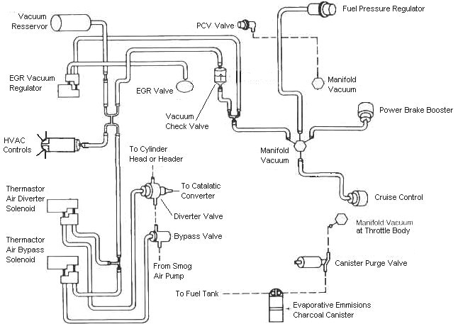
See the vacuum diagram at the end of this post for some links to a lot of very useful 5.0 fox Mustang diagrams and drawings.
If all the intake manifold needs to be removed, both upper and lower then see below for details.
For your automotive work you may want to do a short term rental on a enclosed storage space at one of the self-storage places. Insist on it being wired for electrical for the trouble lights, electrical tools and maybe a heater or fan. If you have another vehicle for a daily driver, park the car there and work on it when you have time and money. That way you can leave it torn apart without arousing the ire of the apartment complex management folks.
Wide band O2 sensors will not work with the Mustang computer. They are designed for Air/Fuel ratio gauges and some specialized aftermarket EFI systems.
The body thread on O2 sensors is probably the same, but I believe that but the O2 sensor wiring connectors are vehicle specific.
The A/F gauges that use the O2 sensor signal will jump all over the place. The reason is that the O2 sensors "switch" between .2 volt lean and .6 volt rich with a curve that looks like the drop off a high cliff. The curve is almost straight up and down, so the voltage shoots from .2 to .6 and back down . again 2 or more times a second at cruse. You won't get much useful information except when the mixture is extremely lean or extremely rich, there is no middle ground. The engine control computer's program knows about the jumping around . The program is designed to use it to not only measure the A/F ratio, but also diagnose the quality of the sensors and their wiring.
Use 43 (Dark Blue/Lt Geen wire) or pin 29 (Dark Green/Pink wire ) on the computer. Use Wire tap-ins from Radio shack P/N 64-3052. The computer is located under the passenger side kick panel. That keeps you from having to crawl under the car and make a weather proof splice in the wiring. You can use either one, or run a SPDT switch and use both. Then you can use the switch to select which side to view.
See the following website for some help from Tmoss (diagram designer) & Stang&2Birds (website host)
http://www.veryuseful.com/mustang/t...91eecPinout.gif
Code 11, computer passed its internal self test. That means the innards of the computer are OK. It does not check the condition of anything connected to the computer, or the ability of the computer to turn on and off any relay or actuator.
Code 41 or 91. Or 43 Three digit code 172 or 176 - O2 sensor indicates system lean. Look for a vacuum leak or failing O2 sensor.
Revised 11-Jan-2015 to add check for fuel pressure out of range
Code 41 is the passenger side sensor, as viewed from the driver's seat.
Code 91 is the driver side sensor, as viewed from the driver's seat.
Code 172 is the passenger side sensor as viewed from the driver's seat.
Code 176 is the driver side sensor, as viewed from the driver's seat.
Code 43 is not side specific according to the Probst Ford Fuel injection book.
The computer sees a lean mixture signal coming from the O2 sensors and tries to compensate by adding more fuel. Many times the end result is an engine that runs pig rich and stinks of unburned fuel.
The following is a Quote from Charles O. Probst, Ford fuel Injection & Electronic Engine control:
"When the mixture is lean, the exhaust gas has oxygen, about the same amount as the ambient air. So the sensor will generate less than 400 Millivolts. Remember lean = less voltage.
When the mixture is rich, there's less oxygen in the exhaust than in the ambient air , so voltage is generated between the two sides of the tip. The voltage is greater than 600 millivolts. Remember rich = more voltage.
Here's a tip: the newer the sensor, the more the voltage changes, swinging from as low as 0.1 volt to as much as 0.9 volt. As an oxygen sensor ages, the voltage changes get smaller and slower - the voltage change lags behind the change in exhaust gas oxygen.
Because the oxygen sensor generates its own voltage, never apply voltage and never measure resistance of the sensor circuit. To measure voltage signals, use an analog voltmeter with a high input impedance, at least 10 megohms. Remember, a digital voltmeter will average a changing voltage." End Quote
Testing the O2 sensors 87-93 5.0 Mustangs
Measuring the O2 sensor voltage at the computer will give you a good idea of how well they are working. You'll have to pull the passenger side kick panel off to gain access to the computer connector. Remove the plastic wiring cover to get to the back side of the wiring. Use a safety pin or paper clip to probe the connections from the rear.
Disconnect the O2 sensor from the harness and use the body side O2 sensor harness as the starting point for testing. Do not measure the resistance of the O2 sensor , you may damage it. Resistance measurements for the O2 sensor harness are made with one meter lead on the O2 sensor harness and the other meter lead on the computer wire or pin for the O2 sensor.
Backside view of the computer wiring connector:
87-90 5.0 Mustangs:
Computer pin 43 Dark blue/Lt green – LH O2 sensor
Computer pin 29 Dark Green/Pink – RH O2 sensor
The computer pins are 29 (L\RH O2 with a dark green/pink wire) and 43 (LH O2 with a dark blue/pink wire). Use the ground next to the computer to ground the voltmeter. The O2 sensor voltage should switch between .2-.9 volt at idle.
91-93 5.0 Mustangs:
Computer pin 43 Red/Black – LH O2 sensor
Computer pin 29 Gray/Lt blue – RH O2 sensor
The computer pins are 29 (LH O2 with a Gray/Lt blue wire) and 43 (RH O2 with a Red/Black wire). Use the ground next to the computer to ground the voltmeter. The O2 sensor voltage should switch between .2-.9 volt at idle.
Testing the O2 sensors 94-95 5.0 Mustangs
Measuring the O2 sensor voltage at the computer will give you a good idea of how well they are working. You'll have to pull the passenger side kick panel off to gain access to the computer connector. Remove the plastic wiring cover to get to the back side of the wiring. Use a safety pin or paper clip to probe the connections from the rear. The computer pins are 29 (LH O2 with a red/black wire) and 27 (RH O2 with a gray/lt blue wire). Use pin 32 (gray/red wire) to ground the voltmeter. The O2 sensor voltage should switch between .2-.9 volt at idle.
Note that all resistance tests must be done with power off. Measuring resistance with a circuit powered on will give false readings and possibly damage the meter. Do not attempt to measure the resistance of the O2 sensors, it may damage them.
Testing the O2 sensor wiring harness
Most of the common multimeters have a resistance scale. Be sure the O2 sensors are disconnected and measure the resistance from the O2 sensor body harness to the pins on the computer. Using the Low Ohms range (usually 200 Ohms) you should see less than 1.5 Ohms.
87-90 5.0 Mustangs:
Computer pin 43 Dark blue/Lt green – LH O2 sensor
Computer pin 29 Dark Green/Pink – RH O2 sensor
Disconnect the connector from the O2 sensor and measure the resistance:
From the Dark blue/Lt green wire in the LH O2 sensor harness and the Dark blue/Lt green wire on the computer pin 43
From the Dark Green/Pink wire on the RH Os sensor harness and the Dark Green/Pink wire on the computer pin 29
91-93 5.0 Mustangs:
Computer pin 43 Red/Black – LH O2 sensor
Computer pin 29 Gray/Lt blue – RH O2 sensor
Disconnect the connector from the O2 sensor and measure the resistance:
From the Red/Black wire in the LH O2 sensor harness and the Red/Black wire on the computer pin 43
From the Dark Green/Pink Gray/Lt blue wire on the RH Os sensor harness and the Gray/Lt blue wire on the computer pin 29
94-95 5.0 Mustangs:
Computer pin 29 Red/Black – LH O2 sensor
Computer pin 27 Gray/Lt blue – RH O2 sensor
From the Red/Black wire in the LH O2 sensor harness and the Red/Black wire on the computer pin 29
From the Dark Green/Pink Gray/Lt blue wire on the RH Os sensor harness and the Gray/Lt blue wire on the computer pin 27
There is a connector between the body harness and the O2 sensor harness. Make sure the connectors are mated together, the contacts and wiring are not damaged and the contacts are clean and not coated with oil.
The O2 sensor ground (orange wire with a ring terminal on it) is in the wiring harness for the fuel injection wiring. I grounded mine to one of the intake manifold bolts
Check the fuel pressure – the fuel pressure is 37-41 PSI with the vacuum disconnected and the engine idling. Fuel pressure out of range can cause the 41 & 91 codes together. It will not cause a single code, only both codes together.
Make sure you have the proper 3 wire O2 sensors. Only the 4 cylinder cars used a 4 wire sensor, which is not compatible with the V8 wiring harness.
Replace the O2 sensors in pairs if replacement is indicated. If one is weak or bad, the other one probably isn't far behind.
Code 41 can also be due to carbon plugging the driver’s side Thermactor air crossover tube on the back of the engine. The tube fills up with carbon and does not pass air to the driver’s side head ports. This puts an excess amount of air in the passenger side exhaust and can set the code 41. Remove the tube and clean it out so that both sides get good airflow: this may be more difficult than it sounds. You need something like a mini rotor-rooter to do the job because of the curves in the tube. Something like the outer spiral jacket of a flexible push-pull cable may be the thing that does the trick.
If you get only code 41 and have changed the sensor, look for vacuum leaks. This is especially true if you are having idle problems. The small plastic tubing is very brittle after many years of the heating it receives. Replace the tubing and check the PVC and the hoses connected to it.
Intake Manifold removal and replacement
Here's some tips...
Tools: a good torque wrench is a must have item. A razor blade scraper that holds a single edge razor blade from Home Depot or Ace hardware is another handy thing. Get a Chilton or Haynes shop manual - you'll need it for the bolt torques and patterns. The intake manifold has an especially odd pattern. You'll need access to a timing light to set the timing after you re-stab the distributor. Look in the A/C repair section for the fuel line tools. They look like little plastic top hats. You will need the 1/2" & 5/8" ones. The hat shaped section goes on facing the large part of the coupling. Then you press hard on the brim until it forces the sleeve into the coupling and releases the spring. You may need someone to pull on the line while you press on the coupling. Put some motor oil on them when you put the line back together.
The A/C Compressor comes off with lines still connected. Mark all the electrical, smog and vacuum lines with tags to help you remember where to re-connect them. If you have a digital camera, take several pictures.
Whatever you do, don't skimp on cleaning the gasket surfaces. New gaskets need to seat against bare metal and not the residue left from the old gaskets in order to seal leak free. This is the most time consuming and tiresome part of the job. Look for little things that need to be replaced like the short hose from the thermostat hosing to the water pump, damaged vacuum lines and hose clamps that are rusted or broken.
Plan on cutting the thermostat to water pump hose, or removing the thermostat housing. Also plan on removing the distributor to get clearance to remove the intake manifold. Remove #1 spark plug, stick your finger in the spark plug hole and crank. When your finger gets air moving past it, stop cranking. Turn the engine until the timing marks line up with the pointer. Now you can pull the distributor out.
My favorite trick that saves time and effort is the stay in place gasket. Be sure that you scrape (don't use a wire brush) all the old gasket material off, then clean all the surfaces with acetone or MEK.
When the surfaces are clean, use weather strip adhesive on the head to manifold surface, and on the side of the gasket that mates to the head. Follow the instructions on the tube or can and when it gets tacky, press the gasket down on the head.
Clean the area where the rubber rails mount to the block in front and in the rear with more acetone or MEK and do the same trick with the weather strip adhesive that you did to the heads.
Coat the rubber seals and the gasket area around the water passages with lots of Blue Silicone gasket sealer and put it together. Wala! no leaks, and no gaskets that shifted out of place.
Get a tube of anti-seize and coat all the bolt threads and under the bolt heads. That will help insure even torque when you tighten the manifold bolts. Plan on re-torquing them a after a weeks worth of driving
Fuel injector seal kits with 2 O rings and a pintle cap (Borg-Warner P/N 274081) are available at Pep Boys auto parts. Cost is about $3 per kit. The pintle caps fit either injectors with a pin sticking out the injector end or 4 with more tiny holes in the injector end. The following are listed at the Borg-Warner site (
http://www.borg-warner.com ) as being resellers of Borg-Warner parts:
http://www.partsplus.com/ or
http://www.autovalue.com/ or
http://www.pepboys.com/ or
http://www.federatedautoparts.com/
Most of the links above have store locators for find a store in your area.
Use motor oil on the O rings when you re-assemble them & everything will slide into place. The gasoline will wash away any excess oil that gets in the wrong places and it will burn up in the combustion chamber.
Consumable items:
Upper manifold gasket
Fel Pro 1250 or equal lower manifold gasket set.
Short formed hose between thermostat hosing and intake manifold
6 ft 7/64" or 1/8" vacuum hose
2 ft 1/2" heater hose
1 1/2 ft 5/8" heater hose
Blue Silicone sealer
ARP antiseize or equal for the bolts
4 each 3/4" hose clamps (spare item in case the old ones are bad)
4 each 1/2" hose clamps (spare item)
What can happen if you don’t use the stay in place gasket…
Ask Nicoleb3x3 about the intake gasket that slipped out of place and caused idle and vacuum leak problems that could not be seen or found by external examination. Spay everything with anything you have, and you won't find the leak...
http://www.gotstang.com/photodisplay.php?iid=111113
In order to get the intake manifold off without you having to be made of rubber to bend and twist at difficult angles, you need to pull the distributor out....
Putting the distributor back in and setting the timing.
Note: If you don't have access to a timing light, most of the larger auto parts stores will rent or loan one if you have a credit card or leave a cash deposit.
Revised 28-Jul-2013 to include warning about putting spark plug leads in a different location to attempt a to fix a distributor incorrectly installed.
You can forget about anything beyond this point if you don't have access to a timing light. You will never get the timing set right without one.
Putting the distributor back in is fairly simple. Pull #1 sparkplug, put your finger in the sparkplug hole, crank the engine until you feel compression. Then line up the TDC mark on the balancer with the pointer on the engine block.
The distributor starts out with the #1 plug wire lined up at about 12:00 with you facing it. Align the rotor to about 11:00, since it will turn clockwise as it slides into place.
Align the distributor rotor up with the #1 position marked on the cap, slide the distributor down into the block, (you may have to wiggle the rotor slightly to get the gear to engage) and then note where the rotor is pointing.
If it still lines up with #1 position on the cap, install the clamp and bolt. If not, pull it out and turn 1 tooth forwards or backwards and try again. Put the #1 spark plug back in and tighten it down, put the clamp on the distributor, but don't tighten it too much, as you will have to move the distributor to set the timing.
Note that there is no such thing as one tooth off on a 5.0 Mustang if you follow the spark plug wire order on the distributor cap. If it doesn't align perfectly with #1 position, you can turn the distributor until it does. The only problem is that if you are too far one way or the other, you can't turn the distributor enough to get the 10-14 degree optimum timing range.
Don't move the wires from the positions shown on the cap on fuel injected engines!!!! The #1 position cast into the cap MUST have the spark plug wire for #1 cylinder in it. Do it differently and the timing for the fuel injectors will be off. The computer uses the PIP sensor to time injector operation by sensing the wide slot in the PIP sensor shutter wheel. If the injector timing of #1 and the firing of #1 do not occur at the right time, the injector timing for all other cylinders will be affected.
Setting the timing:
Paint the mark on the harmonic balancer with paint -choose 10 degrees BTC or 14 degrees BTC or something else if you have NO2 or other power adder. I try to paint TDC red, 10 degrees BTC white and 14 degrees BTC blue.
10 degrees BTC is towards the drivers side marks.
Note: setting the timing beyond the 10 degree mark will give you a little more low speed acceleration.
BUT you will need to run 93 octane to avoid pinging and engine damage. Pinging is very hard to hear at full throttle, so it could be present and you would not hear it.
Simplified diagram of what it looks like. Not all the marks are shown for ease of viewing.
ATC ' ' ' ' ' ' ' ' ' '!' ' ' ' ' ' ' ' ' ' BTC
---------------- >
Direction of Rotation as viewed standing in front of the engine.
The ' is 2 degrees.
The ! is TDC
The
' is 10 degrees BTC
Set the timing 5 marks BTC. Or if you prefer, 5 marks towards the driver's side to get 10 degrees.
To get 14 degrees, set it 7 marks BTC. Or if you prefer, 7 marks towards the driver's side to get 14 degrees.
The paint marks you make are your friends if you do it correctly. They are much easier to see than the marks machined into the harmonic balancer hub.
At this point hook up all the wires, get out the timing light. Connect timing light up to battery & #1 spark plug. Then start the engine.
Remove the SPOUT connector (do a search if you want a picture of the SPOUT connector) It is the 2 pin rectangular plug on the distributor wiring harness. Only the EFI Mustang engines have a SPOUT. If yours is not EFI, check for a SPOUT: if you don’t find one, skip any instructions regarding the SPOUT
Warning: there are only two places the SPOUT should be when you time the engine. The first place is in your pocket while you are setting the timing and the second is back in the harness when you finish. The little bugger is too easy to lose and too hard to find a replacement.
Start engine, loosen distributor hold down with a 1/2" universal socket. Shine the timing light on the marks and turn the distributor until the mark lines up with the edge of the timing pointer. Tighten down the distributor hold down bolt, Replace the SPOUT connector and you are done.
The HO firing order is 1-3-7-2-6-5-4-8.
Non HO firing order is 1-5-4-2-6-3-7-8
Diagrams courtesy of Tmoss & Stang&2birds
Vacuum diagram 89-93 Mustangs
eryuseful.co
See the following website for some help from Tmoss (diagram designer) & Stang&2Birds (website host) for help on 88-95 wiring;
http://www.veryuseful.com/mustang/tech/engine/ Everyone should bookmark this site.
94-95 Mustang wiring diagrams
http://www.veryuseful.com/mustang/tech/engine/#95-95Diagrams
Complete computer, actuator & sensor wiring diagram for 91-93 Mass Air Mustangs
http://www.veryuseful.com/mustang/tech/engine/images/91-93_5.0_EEC_Wiring_Diagram.gif
Complete computer, actuator & sensor wiring diagram for 88-91 Mass Air Mustangs
http://www.veryuseful.com/mustang/tech/engine/images/88-91_5.0_EEC_Wiring_Diagram.gif
Ignition switch wiring
http://www.veryuseful.com/mustang/tech/engine/images/IgnitionSwitchWiring.gif
Fuel, alternator, A/C and ignition wiring
http://www.veryuseful.com/mustang/tech/engine/images/fuel-alt-links-ign-ac.gif
O2 sensor wiring harness
http://www.veryuseful.com/mustang/tech/engine/images/mustangO2Harness.gif
Vacuum diagram 89-93 Mustangs
http://www.veryuseful.com/mustang/tech/engine/images/mustangFoxFordVacuumDiagram.jpg
HVAC vacuum diagram
http://www.veryuseful.com/mustang/tech/engine/images/Mustang_AC_heat_vacuum_controls.gif
TFI module differences & pin out
http://www.veryuseful.com/mustang/tech/engine/images/TFI_5.0_comparison.gif
Fuse box layout
http://www.veryuseful.com/mustang/tech/engine/images/MustangFuseBox.gif
Mustang 5.0 Lights and Radio schematic, by TMoss:
http://www.veryuseful.com/mustang/tech/engine/images/mustangFoxLights-Radio_diag.gif
87-92 power window wiring
http://www.veryuseful.com/mustang/tech/engine/images/mustang87-92 PowerWindowWiring.gif
93 power window wiring
http://www.veryuseful.com/mustang/tech/engine/images/mustang93PowerWindows.gif
T5 Cutaway showing T5 internal parts
http://www.veryuseful.com/mustang/tech/engine/images/5_Speed_Cutaway_Illustrated.jpg
Visual comparison of the Ford Fuel Injectors, picture by TMoss:
http://www.veryuseful.com/mustang/tech/engine/images/Ford_Injector_Guide.jpg
Convertible top motor wiring
http://www.veryuseful.com/mustang/tech/engine/images/mustang88VertTopMotorCkt.gif
Engine mounted fuel injector harness
http://www.veryuseful.com/mustang/tech/engine/images/mustangEngineHarness.gif tang/tech/engine/images/mustang88VertTopMotorCkt.gif