Fuel/ignition/ford Problems

I'm working on a 92 hatch, bought a roller and had a running motor in an 89. Put the motor in the 92, used gas tank from 89, computer, EEC relay, trans. Only thing we really had to wire up was the TFI(distributer plug in) plug had been cut off my 92 roller body so we wired up the plug from the 89. The colors were different but we looked at a 92 plug and matched wires.
It will not start without being primed by spraying gas or ether in it and even after you get it started it will run rough and then finally shut off. Plugs were black(brand new). Fuel pump constantly runs unless you pull the fuel relay off.
I've replaced, fpr, EEC relay, dist cap, iac, egr, clutch safety switch. About to play around with the fuel relays.
I'm at a loss and I'm about to just ls swap the damn thing or put a carb on it.
 
  • Sponsors (?)


You posted a TECH question in Talk. This limits your chances of getting some really good advice, since most guys aren't looking for Tech stuff in the Talk forum.

My advice to you is to twofold:
1.) Send a PM to one of the moderators and have your thread moved to 5.0 Tech
2.) Next time you start a thread, think about where it goes. If you are new to Stangnet, please read the terms of service and give extra thought to where your new thread belongs. There is some help in the text below to help you find the best place to start your thread.
General tech problems go in 5.0 Tech. Tech is for suspension, electrical, brakes, body, engine repair and general troubleshooting on the computer & trouble codes

Tall tales about your 5.0 Mustang, pictures of your 5.0 Mustang project and stories about your last trip to the race track go in 5.0 Talk.

Do this and you'll get the best answers quicker and not get lost in the maze of posts about everything but the type of problem you are having.

Having said that, here’s some help…


Computer will not go into diagnostic mode on 91-93 model 5.0 Mustangs

How it is supposed to work:
The grey/red wire (pin 46) is signal ground for the computer. It provides a dedicated ground for the EGR, Baro, ACT, ECT, & TPS sensors as well as the ground to put the computer into self test mode. If this ground is bad, none of the sensors mentioned will work properly. That will severely affect the car's performance. You will have hard starting, low power and drivability problems. Since it is a dedicated ground, it passes through the computer on its way to the computer main power ground that terminates at the battery pigtail ground. It should read less than 1.5 ohms when measured from anyplace on the engine harness with the battery pigtail ground as the other reference point for the ohmmeter probe.

What sometimes happens is that the test connector grey/red wire gets jumpered to power which either burns up the wiring or burns the trace off the pc board inside the computer. That trace connects pins 46 to pins 40 & 60. Only an experienced electronics technician can open the computer up & repair the trace if it burns up and creates an open circuit.

The STI (Self Test Input ) is jumpered to ground to put the computer into test mode. Jumpering it to power can produce unknown results, including damage to the computer. The ohm test simply verifies that there are no breaks in the wiring between the test connector and the computer input.

How to test the wiring :
With the power off, measure the resistance between the computer test ground (grey/red wire) on the self test connector and battery ground. You should see less than 1.5 ohms.

attachment.php


If that check fails, remove the passenger side kick panel and disconnect the computer connector. There is a 10 MM bolt that holds it in place. Measure the resistance between the grey/red wire and pin 46 on the computer wiring connector : it should be less than 1.5 ohms. More that 1.5 ohms is a wiring problem. If it reads 1.5 ohms or less, then the computer is suspect. On the computer, measure the resistance between pin 46 and pins 40 & 60: it should be less than 1.5 ohms. More that that and the computer’s internal ground has failed, and the computer needs to be replaced.

See http://www.stangnet.com/mustang-forums/749974-computer-issue.html#post7490537 for Joel5.0’s fix for the computer internal signal ground.

If the first ground check was good, there are other wires to check. Measure the resistance between the STI computer self test connector (red/white wire) and pin 48 on the computer main connector: it should be less than 1.5 ohms. More that 1.5 ohms is a wiring problem

The following is a view from the computer side of the computer wiring connector: it is for an A9L, A9P computer.
eec04.gif


a9x-series-computer-connector-wire-side-view-gif.71316


Diagram courtesy of Tmoss & Stang&2birds

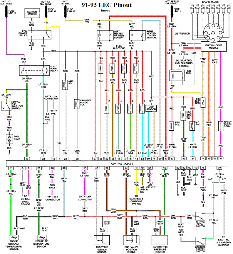
Check out the diagram and notice all the places the grey/red wire goes. Almost every sensor on the engine except the MAF is connected to it.
91-93_5.0_EEC_Wiring_Diagram.gif


See the following website for some help from Tmoss (diagram designer) & Stang&2Birds
(website host) for help on 88-95 wiring http://www.veryuseful.com/mustang/tech/engine

See the graphic for the 10 pin connector circuit layout.
salt-pepper-10-pin-connectors-65-jpg.68512
 
Okay I think I might have figured out where I screwed up. Bear with me on this, I had a wrecked 89lx 5.0 5spd. Bough a 92 roller that was a 5.0 5speed. I dropped the 89 motor in and used the 92 harness. Would this have messed up anything?!
I keep hearing that you can't interchange certain harnesses. So do I need to take the harness from the 89 and redo the whole car or what? I'm at a loss and I believe that's why my KOEO test will not work.
 
It seems that the moderators have taken care of the wrong place for your post.

The engine mounted harness is the same from 86-93, so using it would not make any difference.

Go back and do the Computer will not go into diagnostic mode on 91-93 model 5.0 Mustangs troubleshooter I posted. That will help you find the exact cause of your not being able to dump codes.

If you don't find any problems there, here are the 89 and 92 engine wiring diagrams so that you can compare them side by side. Use an ohmmeter to trace the wires back to the computer to insure continuity: you should see less than 1 ohm between the TFI connector and the computer connector.

a9x-series-computer-connector-wire-side-view-gif.71316


Diagram courtesy of Tmoss & Stang&2birds

Complete computer, actuator & sensor wiring diagram for 88-91 Mass Air Mustangs
88-91_5.0_EEC_Wiring_Diagram.gif


Complete computer, actuator & sensor wiring diagram for 91-93 Mass Air Mustang
91-93_5.0_EEC_Wiring_Diagram.gif


See the following website for some help from Tmoss (diagram designer) & Stang&2Birds (website host) for help on 88-95 wiring http://www.veryuseful.com/mustang/tech/engine/ Everyone should bookmark this site.

Complete computer, actuator & sensor wiring diagram for 91-93 Mass Air Mustangs
http://www.veryuseful.com/mustang/tech/engine/images/91-93_5.0_EEC_Wiring_Diagram.gif

Complete computer, actuator & sensor wiring diagram for 88-91 Mass Air Mustangs
http://www.veryuseful.com/mustang/tech/engine/images/88-91_5.0_EEC_Wiring_Diagram.gif

Ignition switch wiring
http://www.veryuseful.com/mustang/tech/engine/images/IgnitionSwitchWiring.gif

Fuel, alternator, A/C and ignition wiring
http://www.veryuseful.com/mustang/tech/engine/images/fuel-alt-links-ign-ac.gif


Vacuum diagram 89-93 Mustangs
http://www.veryuseful.com/mustang/tech/engine/images/mustangFoxFordVacuumDiagram.jpg

HVAC vacuum diagram
http://www.veryuseful.com/mustang/tech/engine/images/Mustang_AC_heat_vacuum_controls.gif

TFI module differences & pin out
http://www.veryuseful.com/mustang/tech/engine/images/TFI_5.0_comparison.gif

Fuse box layout
http://www.veryuseful.com/mustang/tech/engine/images/MustangFuseBox.gif

87-92 power window wiring
http://www.veryuseful.com/mustang/tech/engine/images/mustang87-92 PowerWindowWiring.gif

93 power window wiring
http://www.veryuseful.com/mustang/tech/engine/images/mustang93PowerWindows.gif
 
Finally got around to testing this out and when I test my ohms between 60-46 and 40-46 I'm getting 4.2 ohms. When I test at the STI to neg battery terminal 4.2 ohms. So how do I go about tracing down the problem and fixing this?
 

Attachments

  • image.jpg
    image.jpg
    620.6 KB · Views: 140
With computer plugged in its 3.3 ohms between STI and the negative terminal. Between STI and all the sensors is .3-.5 ohms. Between STI and body is also 4.2 ohms. So I'm taking a shot in the dark and guessing Its something to do with a body ground?
 
Press the meter probes together when you have the meter on and set to low ohms range. You should get less than 1 ohm. If not. replace the meter batteries with new batteries and do it again.
 
...
Fuel pump constantly runs unless you pull the fuel relay off.
I've replaced, fpr, EEC relay, dist cap, iac, egr, clutch safety switch. About to play around with the fuel relays.
...
Do you mean "constantly runs" with the ignition ON & engine OFF?
You understand that this is not normal?
Is your relay under the driver's seat or in the engine compartment?
It's pretty easy to test just the relay.
 
Yeah I replaced the relay, used two brand new relays. But it constantly runs key on engine off, it's something to do with the wiring.
Jrichker could the problem have anythin to do with the clutch safety switch? The previous owner had a paper clip between the two plugs. I'm certain that those five wires don't need to all be touching. I have a new switch here and will be hooking it up correctly tomorrow. Will update if anything happens or if I burn it to the ground.

If the previous owner jumped all those wires together, the chance of the computer being burnt up is pretty good. One of those wires is the Signal Return, one of the other wires is a 12v circuit for the starter relay. Those two dont mix at all. The fact that you cant get codes is a sign its damaged.

Try grounding the small plug at the test port to a body ground or battery ground and seeing if the codes will flash then.
 
Alright I'll try that in a minute. Checking the main ground right now and fixed the clutch safety problem. The factory jumper was broken in two so it wouldn't show whether it was in nuetral or a gear. I reckon that's why they had the safety switch all jacked up.
 
This is a relay:
Untitled2.jpg

Voltage across the coil, causes current to flow in the coil with a resulting magnetic field that closes the armature. The labels "trip current" & "load current" are reversed. Therefore, small current in coil controls big current in load.

Now the Fuel Pump Relay which looks more like this:
1106rc_09_o%2Bbasic_electrical_relays%2B.jpg

Voltage from the EEC Power Relay is applied to coil of the fuel pump relay. The EEC grounds the coil causing a current to flow creating a magnetic field which closes the contacts of the relay. The relay contact is powered 12V all the time. When relay closes, current flows from battery, through fuse link, through relay contacts, to fuel pump motor, to ground.

Since fuel pump runs all the time with ignition on, and the relay is new & knowing that the wiring is all buggered up, you need to check the wiring to & from the relay before saying the EEC is bad. It's acting like pin-22 is grounded all the time. Nothing else will activate the relay unless there is a short circuit in the wiring. Pay particular attention to the Tan/Lt.Grn wire, with power off, it should have high ohms to EEC ground.