Need 92 5.0 Maf Circuit Help

MFE92

10 Year Member
Aug 25, 2010
1,094
374
124
Phoenix
Cliffs: Is there a connector for the MAF SIG and MAF RTN wires somewhere between the MAF connector and the ECU?

Problem:

I had my car detailed the other day, and it would barely run afterward. I got it towed home on their dime, disconnected every electrical connector under the hood, and aired it out overnight. The next day it ran (extremely rich, down on power) and threw a bunch of codes. I disconnected everything again, sprayed all the connectors (open side and wires side) with MAF cleaner, and let it sit again overnight.

Now when I start it, it immediately throws a CEL and a code 66, MAF voltage too low.

I have checked continuity of the following:

Red VPWR wire from MAF harness to 10-Pin: Good
Black PWR GRND wire from MAF harness to 10-pin: Good
Blue/Orange MAF SIG from one side of MAF connector to the other: Good
Tan/Lt Blue MAF RTN wire from one side of MAF connector to the other: Good

So the connectors are good internally, and the power and ground circuits are good, but the SIG and RTN circuits between the MAF connector and ECU are open. According to my ancient Chilton manual, the MAF SIG and MAF RTN don't go through the 10-pins, they just go directly to the EEC. I haven't accessed the ECU connector to see if there's continuity to it, but I'm starting to wonder if it fried the ECU. I don't see a connector for these anywhere. What am I missing?
 
  • Sponsors (?)


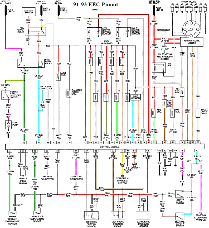
according to the diagram im looking at, theres no "middle-man" connector between the maf and ecu (#24 is the maf):

mustangMainHarness.gif
 
It seems that you have already done most of this, but here's some more input just in case...

Code 66 MAF below minimum test voltage.
Insufficient or no voltage from MAF. Dirty MAF element, bad MAF, bad MAF wiring, missing power to MAF. Check for missing +12 volts on this circuit. Check the two links for a wiring diagram to help you find the red wire for computer power relay switched +12 volts. Check for 12 volts between the red and black wires on the MAF heater (usually pins A & B). while the connector is plugged into the MAF. This may require the use of a couple of safety pins to probe the MAF connector from the back side of it.

a9x-series-computer-connector-wire-side-view-gif.71316


eec04.gif


Diagram courtesy of Tmoss & Stang&2birds
91-93_5.0_EEC_Wiring_Diagram.gif


There are three parts in a MAF: the heater, the sensor element and the amplifier. The heater heats the MAF sensor element causing the resistance to increase. The amplifier buffers the MAF output signal and has a resistor that is laser trimmed to provide an output range compatible with the computer's load tables. Changes in RPM causes the airflow to increase or decrease, changing the voltage output.. The increase of air across the MAF sensor element causes it to cool, allowing more voltage to pass and telling the computer to increase the fuel flow. A decrease in airflow causes the MAF sensor element to get warmer, decreasing the voltage and reducing the fuel flow.

The MAF element is secured by 2 screws & has 1 wiring connector. To clean the element, remove it from the MAF housing and spray it down with electronic parts cleaner or non-inflammable brake parts cleaner (same stuff in a bigger can and cheaper too).


Measure the MAF output at pins C & D on the MAF connector light blue/red and tan/light blue) or at pins 50 & 9 on the computer. Be sure to measure the sensor output by measuring across the pins and not between the pins and ground.

At idle = approximately .6 volt
20 MPH = approximately 1.10 volt
40 MPH = approximately 1.70 volt
60 MPH = approximately 2.10 volt

Check the resistance of the MAF signal wiring. Pin D on the MAF and pin 50 on the computer (dark blue/orange wire) should be less than 2 ohms. Pin C on the MAF and pin 9 on the computer (tan/light blue wire) should be less than 2 ohms.

There should be a minimum of 10K ohms between either pin C or D on the MAF wiring connector and pins A or B. Make your measurement with the MAF disconnected from the wiring harness.


See the following website for some help from Tmoss (diagram designer) & Stang&2Birds (website host) for help on 88-95 wiring http://www.veryuseful.com/mustang/tech/engine/

Ignition switch wiring
http://www.veryuseful.com/mustang/tech/engine/images/IgnitionSwitchWiring.gif

Fuel pump, alternator, ignition & A/C wiring
http://www.veryuseful.com/mustang/tech/engine/images/fuel-alt-links-ign-ac.gif

Computer,. actuator & sensor wiring
http://www.veryuseful.com/mustang/tech/engine/images/88-91_5.0_EEC_Wiring_Diagram.gif

Fuse panel layout
http://www.veryuseful.com/mustang/tech/engine/images/MustangFuseBox.gif

Vacuum routing
http://www.veryuseful.com/mustang/tech/engine/images/mustangFoxFordVacuumDiagram.jpg
 
Yeah, I figured out late last night the MAF SIG circuit doesn't go through the 10-pin.

There should be a minimum of 10K ohms between either pin C or D on the MAF wiring connector and pins A or B. Make your measurement with the MAF disconnected from the wiring harness.

I'm not getting any reading on either the wiring connector or on the MAF when I do this. If I measure across C and D on the MAF, I get 3k ohms. If I measure across A and B on the MAF I get nothing.
 
Yeah, I figured out late last night the MAF SIG circuit doesn't go through the 10-pin.


I'm not getting any reading on either the wiring connector or on the MAF when I do this. If I measure across C and D on the MAF, I get 3k ohms. If I measure across A and B on the MAF I get nothing.

Press the meter lead tips together: if you get the same reading results as when you measure the A&B pins, you are OK. Heater elements increase in resistance as they heat up.

If the results are different, that's a clue that the MAF heater element has burned out and is an open circuit. Time for a new MAF sensor. If it is an aftermarket MAF like a Pro-M, you get to send it back to the manufacturer. If it's a C&L, you get to replace it with a stock MAF sensor like the one that originally came with the car.