Code 23 - Throttle sensor out of range or throttle set too high –
Revised 02-Jul-2009 to update TPS setting procedure.
TPS needs to be reset to below 1.2 volts at idle.
Setting the TPS voltage
You'll need a Digital Voltmeter (DVM) to do the job.
Wire colors & functions:
Orange/white = 5 volt VREF from the computer
Dark Green/lt green = TPS output to computer
Black/white = Signal ground from computer
Always use the Dark Green/lt green & Black/white wires to set the TPS base voltage.
Do the test with the ignition switch in the Run position without the engine running.
Use the Orange/white & Black white wires to verify the TPS has the correct 5 volts source from the computer.
Setting the TPS: you'll need a good Digital Voltmeter (DVM) to do the job. Set the TPS voltage at .5- 1.1 range. Because of the variables involved with the tolerances of both computer and DVM, I would shoot for somewhere between .6 and 1.0 volts. Unless you have a Fluke or other high grade DVM, the second digit past the decimal point on cheap DVM’s is probably fantasy.
Since the computer zeros out the TPS voltage every time it powers up, playing with the settings isn't an effective aid to performance or drivability. The main purpose of checking the TPS is to make sure it isn't way out of range and causing problems.
The Orange/White wire is the VREF 5 volts from the computer. You use the Dark Green/Lt green wire (TPS signal) and the Black/White wire (TPS ground) to set the TPS. Use a pair of safety pins to probe the TPS connector from the rear of the connector. You may find it a little difficult to make a good connection, but keep trying. Put the safety pins in the Dark Green/Lt green wire and Black/White wire. Make sure the ignition switch is in the Run position but the engine isn't running.
Always adjust the TPS and Idle with the engine at operating temp. Dive it around for a bit if you can and get it nice and warm.
When you probe the leads of the TPS, do not use an engine ground, put the ground probe into the lead of the TPS. You should be connecting both meter probes to the TPS and not one to the TPS and the other to ground.
The TPS is a variable resistor, must like the volume control knob on a cheap radio. We have all heard them crackle and pop when the volume is adjusted. The TPS sensor has the same problem: wear on the resistor element makes places that create electrical noise. This electrical noise confuses the computer, because it expects to see a smooth increase or decrease as the throttle is opened or closed.
TPS testing: most of the time a failed TPS will set code 23 or 63, but not always. Use either an analog meter or a DVM with an analog bar graph and connect the leads as instructed above. Turn the ignition switch to the Run position, but do not start the engine. Note the voltage with the throttle closed. Slowly open the throttle and watch the voltage increase smoothly, slowly close the throttle and watch the voltage decrease smoothly. If the voltage jumps around and isn’t smooth, the TPS has some worn places in the resistor element. When the throttle is closed, make sure that the voltage is the same as what it was when you started. If it varies more than 10%, the TPS is suspect of being worn in the idle range of its travel.
See
Ford Fuel Injection Wiring Harnesses for more wiring help & 10 pin connector diagrams
Code 63 - Throttle Position Sensor (TPS) signal too low.
Revised 02-Jul-2009 to update TPS setting procedure & add 10 pin connector layout.
Vref missing (5 volt reference voltage supplied by the computer), bad connections or damaged wiring, TPS sensor failed, TPS sensor way out of adjustment. Use a DVM to check for 5 volts on the Orange wire. If it is missing, look for +5 volts at the Orange wire on the EGR or MAP/Baro sensor located on the firewall near the center of the car. If there is +5 volts on the MAP/Baro sensor, but not on the EGR, clean the #2 & #5 pin on the white 10 pin connector. If there is +5 volts on the EGR but not on the TPS, look for bad wiring inside the engine fuel injector harness.
Setting the TPS voltage
You'll need a Digital Voltmeter (DVM) to do the job.
Wire colors & functions:
Orange/white = 5 volt VREF from the computer
Dark Green/lt green = TPS output to computer
Black/white = Signal ground from computer
Always use the Dark Green/lt green & Black/white wires to set the TPS base voltage.
Do the test with the ignition switch in the Run position without the engine running.
Use the Orange/white & Black white wires to verify the TPS has the correct 5 volts source from the computer.
Setting the TPS: you'll need a good Digital Voltmeter (DVM) to do the job. Set the TPS voltage at .5- 1.1 range. Because of the variables involved with the tolerances of both computer and DVM, I would shoot for somewhere between .6 and 1.0 volts. Unless you have a Fluke or other high grade DVM, the second digit past the decimal point on cheap DVM’s is probably fantasy.
Since the computer zeros out the TPS voltage every time it powers up, playing with the settings isn't an effective aid to performance or drivability. The main purpose of checking the TPS is to make sure it isn't way out of range and causing problems.
The Orange/White wire is the VREF 5 volts from the computer. You use the Dark Green/Lt green wire (TPS signal) and the Black/White wire (TPS ground) to set the TPS. Use a pair of safety pins to probe the TPS connector from the rear of the connector. You may find it a little difficult to make a good connection, but keep trying. Put the safety pins in the Dark Green/Lt green wire and Black/White wire. Make sure the ignition switch is in the Run position but the engine isn't running.
Always adjust the TPS and Idle with the engine at operating temp. Dive it around for a bit if you can and get it nice and warm.
When you probe the leads of the TPS, do not use an engine ground, put the ground probe into the lead of the TPS. You should be connecting both meter probes to the TPS and not one to the TPS and the other to ground.
The TPS is a variable resistor, must like the volume control knob on a cheap radio. We have all heard them crackle and pop when the volume is adjusted. The TPS sensor has the same problem: wear on the resistor element makes places that create electrical noise. This electrical noise confuses the computer, because it expects to see a smooth increase or decrease as the throttle is opened or closed.
TPS testing: most of the time a failed TPS will set code 23 or 63, but not always. Use either an analog meter or a DVM with an analog bar graph and connect the leads as instructed above. Turn the ignition switch to the Run position, but do not start the engine. Note the voltage with the throttle closed. Slowly open the throttle and watch the voltage increase smoothly, slowly close the throttle and watch the voltage decrease smoothly. If the voltage jumps around and isn’t smooth, the TPS has some worn places in the resistor element. When the throttle is closed, make sure that the voltage is the same as what it was when you started. If it varies more than 10%, the TPS is suspect of being worn in the idle range of its travel.
Code 34 Or 334 - EGR voltage above closed limit - Failed sensor, carbon between EGR pintle valve and seat holding the valve off its seat or vacuum control problems. Remove the EGR valve and clean it with carbon remover. Prior to re-installing see if you can blow air through the flange side of the EGR by mouth. If it leaks, there is carbon stuck on the pintle valve seat, replace the EGR valve ($85-$95).
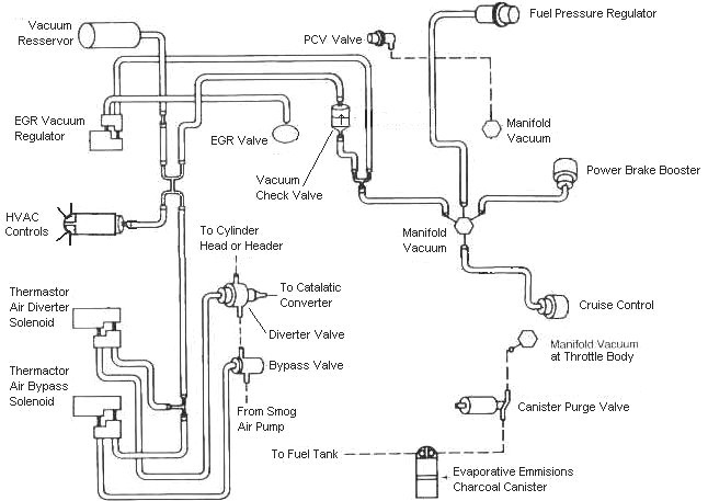
Vacuum control problems:
If someone has misrouted the EGR vacuum plumbing or the EVR (Electronic Vacuum Regulator) has failed, you can get this code.
Diagram courtesy of Tmoss & Stang&2birds
EGR test procedure courtesy of cjones
to check the EGR valve:
bring the engine to normal temp.
connect a vacuum pump to the EGR Valve or
see the EGR test jig drawing below. Connnect the test jig or to directly to manifold vacuum.
Do not connect the EGR test jig to the EVR (Electronic Vacuum Regulator).
apply 5in vacuum to the valve.
Using the test jig, use your finger to vary the vacuum
if engine stumbled or died then EGR Valve and passage(there is a passageway through the heads and intake) are good.
if engine did NOT stumble or die then either the EGR Valve is bad and/or the passage is blocked.
if engine stumbled,
connect EGR test jig to the hose coming off of the EGR Valve.
Use your finger to cap the open port on the vacuum tee.
snap throttle to 2500 RPM (remember snap the throttle don't hold it there).
did the vacuum gauge show about 2-5 in vacuum?
if not the EVR has failed
EGR test jig
If the blow by test passes, and you have replaced the sensor, then you have electrical ground problems. Check the resistance between the black/white wire on the MAP/BARO sensor and then the black/white wire on the EGR and the same wire on the TPS. It should be less than 1.5 ohm. Next check the resistance between the black/white wire and the negative battery post. It should be less than 1.5 ohm.
Note that all resistance tests must be done with power off. Measuring resistance with a circuit powered on will give false readings and possibly damage the meter.
Let’s put on our Inspector Gadget propeller head beanies and think about how this works:
The EGR sensor is a variable resistor with ground on one leg and Vref (5 volts) on the other. Its’ resistance ranges from 4000 to 5500 Ohms measured between Vref & ground, depending on the sensor. The center connection of the variable resistor is the slider that moves in response to the amount of vacuum applied. The slider has some minimum value of resistance greater than 100 ohms so that the computer always sees a voltage present at its’ input. If the value was 0 ohms, there would be no voltage output. Then the computer would not be able to distinguish between a properly functioning sensor and one that had a broken wire or bad connection. The EGR I have in hand reads 700 Ohms between the slider (EPV) and ground (SIG RTN) at rest with no vacuum applied. The EGR valve or sensor may cause the voltage to be above closed limits due to the manufacturing tolerances that cause the EGR sensor to rest at a higher position than it should.
The following sensors are connected to the white 10 pin connector (salt & pepper engine harness connectors)
This will affect idle quality by diluting the intake air charge
See the following website for some help from Tmoss (diagram designer) & Stang&2Birds (website host) for help on 88-95 wiring Mustang FAQ - Engine Information Everyone should bookmark this site.
Ignition switch wiring
http://www.veryuseful.com/mustang/tech/engine/images/IgnitionSwitchWiring.gif
Fuel, alternator, A/C and ignition wiring
http://www.veryuseful.com/mustang/tech/engine/images/fuel-alt-links-ign-ac.gif
Complete computer, actuator & sensor wiring diagram for 88-91 Mass Air Mustangs
http://www.veryuseful.com/mustang/tech/engine/images/88-91_5.0_EEC_Wiring_Diagram.gif
Complete computer, actuator & sensor wiring diagram for 91-93 Mass Air Mustangs
http://www.veryuseful.com/mustang/tech/engine/images/91-93_5.0_EEC_Wiring_Diagram.gif
Complete computer, actuator & sensor wiring diagram for94-95 Mass Air Mustangs
http://www.veryuseful.com/mustang/tech/engine/images/94-95_5.0_EEC_Wiring_Diagram.gif
Vacuum diagram 89-93 Mustangs
http://www.veryuseful.com/mustang/tech/engine/images/mustangFoxFordVacuumDiagram.jpg
HVAC vacuum diagram
http://www.veryuseful.com/mustang/tech/engine/images/Mustang_AC_heat_vacuum_controls.gif
TFI module differences & pinout
http://www.veryuseful.com/mustang/tech/engine/images/TFI_5.0_comparison.gif
Fuse box layout
http://www.veryuseful.com/mustang/tech/engine/images/MustangFuseBox.gif
Code 67 - clutch not depressed (5 speed) or car not in neutral or park (auto) or A/C in On position when codes
where dumped. Possible neutral safety switch or wiring problem. This code may prevent you from running the Key On
Engine On tests. You can generally ignore this code, since it has no effect on engine performance.
The computer wants to make sure the A/C is off due to the added load on the engine for the engine running tests. It also
checks to see that the transmission is in Neutral or the clutch depressed (T5, T56, Tremec 3550 & TKO). This prevents
the diagnostics from being run when the car is driven. Key On Engine Running test mode takes the throttle control away
from the driver for several tests. This could prove hazardous if the computer was jumpered into test mode and then driven.
The NSS code 67 can be bypassed for testing. You will need to temporarily ground computer pin 30 to the chassis.
Computer pin 30 uses a Lt blue/yellow wire. Remove the passenger side kick panel and then remove the plastic cover from
the computer wiring connector. Use a safety pin to probe the connector from the rear. Jumper the safety pin to the
ground near the computer.