
Thanks for the good info. It is a mass air (Im assuming as i have a MAF). It currently has a blow off have connected to the pipe between throttle body and SC. The blow off valve In turn has a small hose leading into the air intake manifold.No boost controller is necessary, that is strictly a turbo thing and will not apply to a centrifugal supercharger.
I would recommend a mechanical boost gauge, something like this http://www.summitracing.com/parts/atm-3401/overview/
This would be plumbed directly into the manifold after the throttle body
Is the car Mass Air or Speed Density? If Speed density you can use a traditional blow off valve and vent to the atmosphere, this would only be needed if the blower is producing more than 5-6 lbs of boost
If the car is Mass Air you MUST use a recirculation valve when boost pressure is over 5-6 lbs ( blow through mass air excluded ). This would get plumbed between the discharge tube and intake tube and recirculates previously metered air.
This is what I would recommend for applications that see 6-12 lbs of boost 8D001-004 | Vortech Superchargers
The only way to adjust the boost would be by changing the pulley on the blower or the pulley on the crankshaft, you must also be mindful of impeller speeds. Typically I do not recommend changing any pulleys on the SN 89,93,2000 blowers as they don't withstand the torture that today's blowers easily handle.
You are using an out of date browser. It may not display this or other websites correctly.
You should upgrade or use an alternative browser.
You should upgrade or use an alternative browser.
Progress Thread Project Swampfox
- Thread starter Project Swampfox
- Start date
-
Sponsors (?)
Also I won't be messing with increasing boost. I want low boost on this build. It just for "cool" factor. I plan on cruising this thing to the movies and to get icecream with the wife and to shows. I'll probably never race it.No boost controller is necessary, that is strictly a turbo thing and will not apply to a centrifugal supercharger.
I would recommend a mechanical boost gauge, something like this http://www.summitracing.com/parts/atm-3401/overview/
This would be plumbed directly into the manifold after the throttle body
Is the car Mass Air or Speed Density? If Speed density you can use a traditional blow off valve and vent to the atmosphere, this would only be needed if the blower is producing more than 5-6 lbs of boost
If the car is Mass Air you MUST use a recirculation valve when boost pressure is over 5-6 lbs ( blow through mass air excluded ). This would get plumbed between the discharge tube and intake tube and recirculates previously metered air.
This is what I would recommend for applications that see 6-12 lbs of boost 8D001-004 | Vortech Superchargers
The only way to adjust the boost would be by changing the pulley on the blower or the pulley on the crankshaft, you must also be mindful of impeller speeds. Typically I do not recommend changing any pulleys on the SN 89,93,2000 blowers as they don't withstand the torture that today's blowers easily handle.

Looks like somebody went to Home Depot for the intake piping  Anderson Power Pipe bro!!
P.S. Is that line from the SC an oil line? Where does that white line go to?
Anderson Power Pipe bro!!P.S. Is that line from the SC an oil line? Where does that white line go to?
I know bro, tell me about it FML. The white line is nylon I think it's psi for the boost guage. No oil, the SC is contained lubrication. Uses trans fluid.Looks like somebody went to Home Depot for the intake piping
P.S. Is that line from the SC an oil line? Where does that white line go to?
I don't think I'm going to get an Anderson though. Seems cheaper to fab my own set up out of some polished alum and joints.Looks like somebody went to Home Depot for the intake piping
P.S. Is that line from the SC an oil line? Where does that white line go to?

I can see that the UPR is fully functional, but visually its kind of+1 for UPR. I forget they make them too but only for boost setups. My $ would've went to them if they had a pipe for N/A @Sharad
 . That's the only reason I wanted to bend my own pipes. If I can fab one for less then the cost of an Anderson, I'll do it. If not, I just go ahead and get one lol. Trying to spend my last few pennies this month on a new hood. The one I have isnt tall enough and my intake manifold is resting on it. I'd like a simple 2.5-3 inch cowl. But I haven't finished sawing off my arm and leg for it yet.
Poking around a little after work today.
 I carefully continued to strip the wrap off this harness in prep to relocate to under pinch weld along with the brake lines.

 I plan to relocate these assemblies into the passenger fender.
 Where the hell is this supposed to mount and if you guys are relocating, where to? Mine was awesomely just chilling on my freaking headers. No biggy.
 And lastly I test fitted my a/c delete. Looks good just gonna pick up some fresh bolts from Napa tomorrow. Might catch flame for this one but I like it better than the ford racing delete. I like the P/S out of sight.
**NOTE
I test fit my Draglites and it appears I need longer studs. Found this to be the norm through searching. But any suggestions would be cool. I plan to run a spacer. They fit currently (nothing a BFH won't help) but I'd like to pull them out a half inch or so stance wise.
Hope you guys are doing well.
Last edited:
Are you going to pull the motor? That engine bay makes me want to barf! What's with all the rust? A lot of moisture where you are?
The picture of you holding the sensor in your left hand is your BAP sensor. You need this for your MAF sensor. There is enough wire for you to mount it lower on your firewall near your transmission tunnel. I don't have a BAP since I went with an aftermarket computer programming system that doesn't require it. Not sure what the other things are, you need to zoom out a little more so we can see what area you're in. I don't have smog on my car and deleted my thermactor solenoilds. They are located on the back side of the passenger shock tower. I'm not sure if that's what you're taking a picture of. There will be two of them close together. Are you keeping your smog stuff? EGR? Smog pump?
The picture of you holding the sensor in your left hand is your BAP sensor. You need this for your MAF sensor. There is enough wire for you to mount it lower on your firewall near your transmission tunnel. I don't have a BAP since I went with an aftermarket computer programming system that doesn't require it. Not sure what the other things are, you need to zoom out a little more so we can see what area you're in. I don't have smog on my car and deleted my thermactor solenoilds. They are located on the back side of the passenger shock tower. I'm not sure if that's what you're taking a picture of. There will be two of them close together. Are you keeping your smog stuff? EGR? Smog pump?
Are you going to pull the motor? That engine bay makes me want to barf! What's with all the rust? A lot of moisture where you are?
The picture of you holding the sensor in your left hand is your BAP sensor. You need this for your MAF sensor. There is enough wire for you to mount it lower on your firewall near your transmission tunnel. I don't have a BAP since I went with an aftermarket computer programming system that doesn't require it. Not sure what the other things are, you need to zoom out a little more so we can see what area you're in. I don't have smog on my car and deleted my thermactor solenoilds. They are located on the back side of the passenger shock tower. I'm not sure if that's what you're taking a picture of. There will be two of them close together. Are you keeping your smog stuff? EGR? Smog pump?
Yes I plan on pulling the motor. Not until the winter though. I just don't have the space. The previous owner left me a nightmare of wires, surface rust and rattle can paint. The car was bought in Florida (hence the rust) I brought it up to VA with me. I'll get her right though. The smog is all deleted. I'll try to make my pics better.
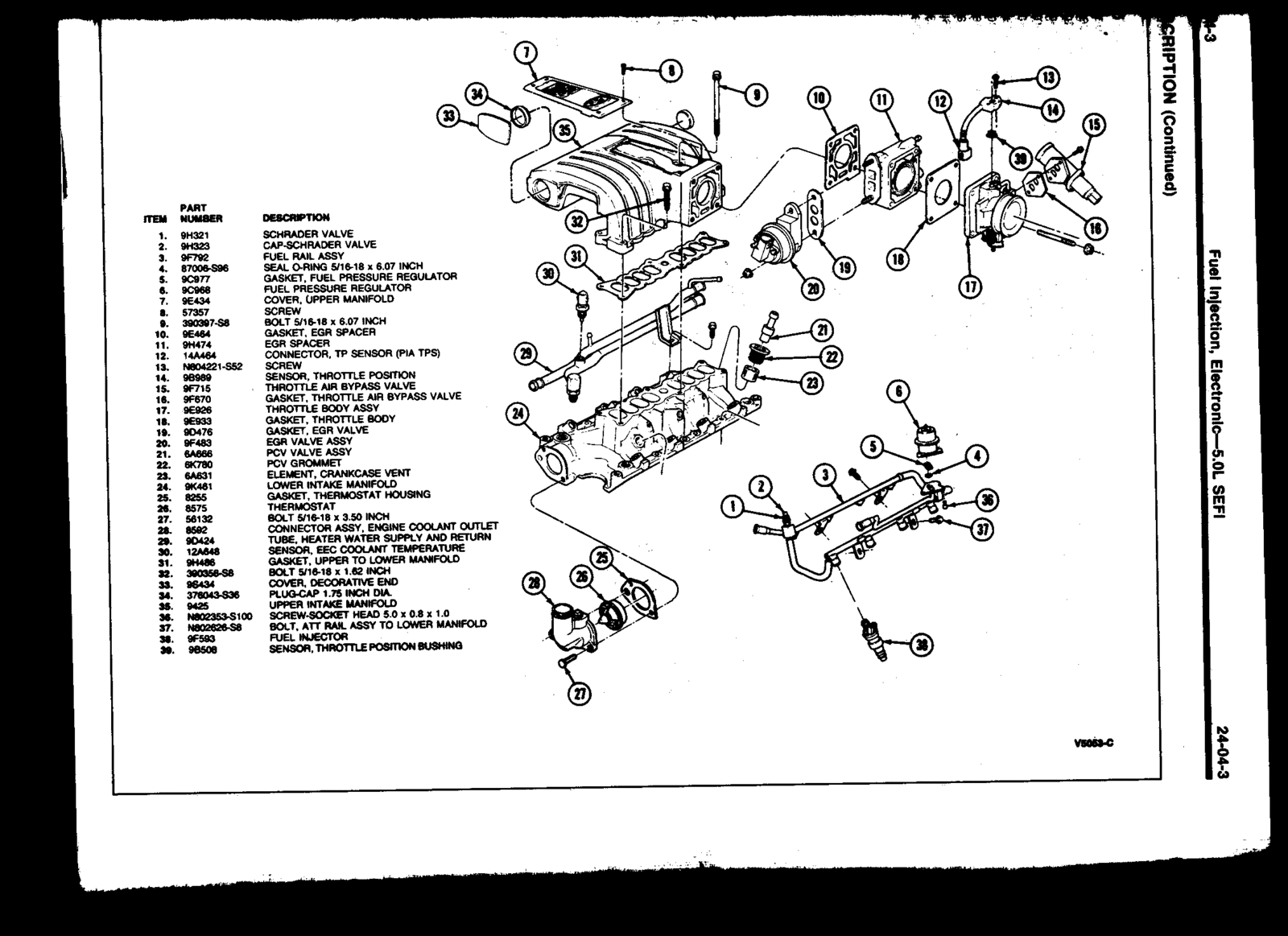
This is the item I had a shoddy pic of. It leads to my injectors. I'm just curious as to its original mounting position. When I got the car it was just hanging bea the tran tunnel. It looks like it just snaps into place somewhere.


@FoxMustangLvr
@FoxMustangLvr
mikestang63
SN Certified Technician
Those are your Salt and Pepper shaker connectors. From the factory the plastic clips on the top goes under the top plate of the stock manifold.

Most guys end up taking them off the plastic clip and tucking htem away back down along the firewall so they are hidden.
Most guys end up taking them off the plastic clip and tucking htem away back down along the firewall so they are hidden.
Ok cool. Thanks a lot.Those are your Salt and Pepper shaker connectors. From the factory the plastic clips on the top goes under the top plate of the stock manifold.
Most guys end up taking them off the plastic clip and tucking htem away back down along the firewall so they are hidden.
Hey guys. So for the past couple of days I've been working on my trunk. Took the rust in there down to the metal and hit it with some rustoleum. In the winter I'll sand it up and paint whatever color I go with on the exterior. I'm going to address the small holes I have near the weatherstrip inthe winter as well when I buy my welder. I'm debating dynamating the trunk but in going to wait until it's paint officially and there's 0 trace of rust.
Battery box
Got the battery box 90% mounted. Swiveled my tank out of the way so I could mount on the passenger side. Was pretty easy (would be easier if the tank wasn't full ). Looks decent. Pics soon. Got the box from Taylor as a relocation kit for like 100$.
Couple questions to help me along on the relocation,
1. I saw that my battery was ground to block when it was up front. Other than that, that was the only thing direct to my (-) terminal. What's a good ground point in the rear of the vehicle to keep from running a line all the way back to the block?
2. @FoxMustangLvr on the pics you shot me of your setup, you have a 3G amp fuse in your driver fender. Exactly which lines should I be integrating a fuse? I don't have a fuses currently but would love to (and probably have to) fuse a few of these power sources.
3. I have been told extending lines to mount my MSD 6AL in the trunk shouldn't be and issue. Do any of you have input or suggestions about this?
Other then that I'm enjoying my self with this build so far. My harness is worked out for the most part in the bay. Currently tackling these vacuum lines. Hope you guys are enjoying the weather. I'm seeing more and more foxes rolling around.
Battery box
Got the battery box 90% mounted. Swiveled my tank out of the way so I could mount on the passenger side. Was pretty easy (would be easier if the tank wasn't full
). Looks decent. Pics soon. Got the box from Taylor as a relocation kit for like 100$. Couple questions to help me along on the relocation,
1. I saw that my battery was ground to block when it was up front. Other than that, that was the only thing direct to my (-) terminal. What's a good ground point in the rear of the vehicle to keep from running a line all the way back to the block?
2. @FoxMustangLvr on the pics you shot me of your setup, you have a 3G amp fuse in your driver fender. Exactly which lines should I be integrating a fuse? I don't have a fuses currently but would love to (and probably have to) fuse a few of these power sources.
3. I have been told extending lines to mount my MSD 6AL in the trunk shouldn't be and issue. Do any of you have input or suggestions about this?
Other then that I'm enjoying my self with this build so far. My harness is worked out for the most part in the bay. Currently tackling these vacuum lines. Hope you guys are enjoying the weather. I'm seeing more and more foxes rolling around.
Info for trunk located battery grounds and fused line for 3G is in this post from Jrichker. I purchased the 3G kit from Latemodel Resto. I've read that some people only did a ground from the battery to trunk body or grounded the battery to the quad shock mount and did NOT run an additional ground from that point to the engine block with success. Jrichker and few others will highly recommend that you run the ground from the trunk body location to the engine block with #1 or 1/0 and then from the block to the body with #4.
As requested, plus a few more you may need...
For a battery cut off switch, see Moroso Performance Products: It's your passion for racing that drives us!
is the switch Moroso Performance Products: It's your passion for racing that drives us! is the installation instructions.
Use the super duty switch and the following tech note to wire it and you will
be good to go.
Use the Moroso plan for the alternator wiring and you risk a fire. The 10 gauge wire they recommend is even less adequate that the stock Mustang wiring.
There is a solution, but it will require about 40' of 18 gauge green wire.
Wire the battery to the two 1/2" posts as shown in the diagram.
The alternator requires a different approach. On the small alternator plug there is a green wire. It is the sense lead that turns the regulator on when the ignition switch is in the run position. Cut the green wire and solder the 40' of green wire between the two pieces. Use some heat shrink to cover the splices. See Fordfuelinjection.com for some excellent help on soldering & using heat shrink tubing.
Run the green wire back to the Moroso switch and cut off the excess wire. Try to run the green wire inside the car and protect it from getting cut or chaffed. Crimp a 18 gauge ring terminal (red is 18 gauge color code for the crimp on terminals) on each wire. Bolt one ring terminal to each of the 3/16" studs. Do not add the jumper between the 1/2" stud and the 3/16" stud as shown it the
Moroso diagram.
How it works:
The green wire is the ignition on sense feed to the regulator. It supplies a turn on signal to the regulator when the ignition switch is in the Run position. Turn the Moroso switch to off, and the sense voltage goes away, the voltage regulator shuts off and the alternator quits making power.
The fuse & wiring in the following diagram are for a 3G alternator. The stock alternator uses a dark green fuse link wire that connects to 2 black/orange wires. Always leave them connected to the starter solenoid even if you have a 3G alternator.

Rear mounted battery ground wiring. Follow this plan and you will have zero ground problems.
One 1 gauge or 1/0 gauge wire from battery negative post to a clean shiny spot on the chassis near the battery. Use a 5/16” bolt and bolt it down to make the rear ground. Use a 1 gauge or 1/0 gauge wire from the rear ground bolt to a clean shiny spot on the block.
One 4 gauge wire from the block where you connected the battery ground wire to the chassis ground where the battery was mounted up front. Use a 5/16” bolt and bolt down the 4 gauge engine to chassis ground, make sure that it the metal around the bolt is clean & shiny. This is the alternator power ground.

The computer has a dedicated power ground wire with a cylindrical quick connect (about 2 ½”long by 1” diameter. It comes out of the wiring harness near the ignition coil & starter solenoid (or relay). Be sure to bolt it to the chassis ground in the same place as you bolted the alternator power ground. This is an absolute don’t overlook it item for EFI cars
Note: The quick disconnect may have fallen victim to damage or removal by a previous owner. However, it is still of utmost importance that the black/green wires have a high quality ground..
Picture courtesy timewarped1972
Crimp or even better, solder the lugs on the all the wire. The local auto stereo shop will have them if the auto parts store doesn't. Use some heat shrink tubing to cover the lugs and make things look nice.
Starter solenoid wiring for 86-91 Mustang

Starter solenoid wiring 92-93 Mustang or earlier Mustang with upgraded high torque mini starter.


See the following website for some help from Tmoss (diagram designer) & Stang&2Birds (website host) for help on 88-95 wiring Mustang FAQ - Wiring & Engine Info Everyone should bookmark this site.
Complete computer, actuator & sensor wiring diagram for 91-93 Mass Air Mustangs
http://www.veryuseful.com/mustang/tech/engine/images/91-93_5.0_EEC_Wiring_Diagram.gif
Complete computer, actuator & sensor wiring diagram for 88-91 Mass Air Mustangs
http://www.veryuseful.com/mustang/tech/engine/images/88-91_5.0_EEC_Wiring_Diagram.gif
Ignition switch wiring
http://www.veryuseful.com/mustang/tech/engine/images/IgnitionSwitchWiring.gif
Fuel, alternator, A/C and ignition wiring
http://www.veryuseful.com/mustang/tech/engine/images/fuel-alt-links-ign-ac.gif
O2 sensor wiring harness
http://www.veryuseful.com/mustang/tech/engine/images/mustangO2Harness.gif
Vacuum diagram 89-93 Mustangs
http://www.veryuseful.com/mustang/tech/engine/images/mustangFoxFordVacuumDiagram.jpg
HVAC vacuum diagram
http://www.veryuseful.com/mustang/tech/engine/images/Mustang_AC_heat_vacuum_controls.gif
TFI module differences & pin out
http://www.veryuseful.com/mustang/tech/engine/images/TFI_5.0_comparison.gif
Fuse box layout
http://www.veryuseful.com/mustang/tech/engine/images/MustangFuseBox.gif
87-92 power window wiring
http://www.veryuseful.com/mustang/tech/engine/images/mustang87-92 PowerWindowWiring.gif
93 power window wiring
http://www.veryuseful.com/mustang/tech/engine/images/mustang93PowerWindows.gif
T5 Cutaway showing T5 internal parts
http://www.veryuseful.com/mustang/tech/engine/images/5_Speed_Cutaway_Illustrated.jpg
Visual comparison of the Ford Fuel Injectors, picture by TMoss:
http://www.veryuseful.com/mustang/tech/engine/images/Ford_Injector_Guide.jpg
Thanks man. I might just run the line. I don't want to change up too much.Info for trunk located battery grounds and fused line for 3G is in this post from Jrichker. I purchased the 3G kit from Latemodel Resto. I've read that some people only did a ground from the battery to trunk body or grounded the battery to the quad shock mount and did NOT run an additional ground from that point to the engine block with success. Jrichker and few others will highly recommend that you run the ground from the trunk body location to the engine block with #1 or 1/0 and then from the block to the body with #4.
Similar threads
- Replies
- 1
- Views
- 381
- Replies
- 2
- Views
- 1K
- Replies
- 20
- Views
- 3K
- Replies
- 19
- Views
- 2K