TPS fluctuates from 1.0v-6.5v engine running

Here's the problem, the tps voltage was set at .98v, and it rises smoothly and normally to 4.8v at wot, all done with key on engine off. while the car is running though, voltage keeps jumping around, 1v, 3.6, 2.0, 6.5,5.0,1.9, etc.

I have already changed the tps to double check that, no change. Is the pcm the next thing? Its a whole new setup, the car ran great with a 302, no issues. now I have a 351w and a turbo. no change to the wiring harness, still an A9L computer. only mods to the electrical since the 302 was an external fuel pump.

The tuner has put a "base" program on a chip to start with. Unplugging the chip has no change. Any help would be great, trying to stick it on the dyno tomorrow.
 
  • Sponsors (?)


You might want to check your alternator. If it has a bad diode it will do that. Check for what they refer to as ripple. The spikes of AC voltage will make the sensors do all kinds of stupid things.
 
What are you using for connection points (sig return or a metal ground) and how are you connecting your meter to the wires?
 
Setting the TPS: you'll need a good Digital Voltmeter (DVM) to do the job. Set the TPS voltage at .5- 1.1 range. Because of the variables involved with the tolerances of both computer and DVM, I would shoot for somewhere between .6 and 1.0 volts. Unless you have a Fluke or other high grade DVM, the second digit past the decimal point on cheap DVM’s is probably fantasy. Since the computer zeros out the TPS voltage every time it powers up, playing with the settings isn't an effective aid to performance or drivability. The main purpose of checking the TPS is to make sure it isn't way out of range and causing problems.


Wire colors & functions:
Orange/white = 5 volt VREF from the computer
Dark Green/lt green = TPS output to computer
Black/white = Signal ground from computer

TPS troubleshooting steps:
1.) Use the Orange/white & Black white wires to verify the TPS has the correct 5 volts source from the computer.
2.) Use the Dark Green/lt green & Black/white wires to set the TPS base voltage. Try this... All you need is less than 1.0 volt at idle and more than 4.25 at Wide Open Throttle (WOT). You'll need a voltmeter with a 1 or 3 volt low scale to do the job.

The Orange/White wire is the VREF 5 volts from the computer. You use the Dark Green/Lt green wire (TPS signal) and the Black/White wire (TPS ground) to set the TPS. Use a pair of safety pins to probe the TPS connector from the rear of the connector. You may find it a little difficult to make a good connection, but keep trying. Put the safety pins in the Dark Green/Lt green wire and Black/White wire. Make sure the ignition switch is in the Run position but the engine isn't running.

Here’s a TPS tip I got from NoGo50

When you installed the sensor make sure you place it on the peg right and then tighten it down properly. Loosen the back screw a tiny bit so the sensor can pivot and loosen the front screw enough so you can move it just a little in very small increments. I wouldn’t try to adjust it using marks.

(copied from MustangMax, Glendale AZ)

A.) Always adjust the TPS and Idle with the engine at operating temp. Dive it around for a bit if you can and get it nice and warm.

B.) When you probe the leads of the TPS, do not use an engine ground, put the ground probe into the lead of the TPS. You should be connecting both meter probes to the TPS and not one to the TPS and the other to ground.

C.) Always reset the computer whenever you adjust the TPS or clean/change any sensors. I just pull the battery lead for 10 minutes.

D.) The key is to adjust the TPS voltage and reset the computer whenever the idle screw is changed.

The TPS is a variable resistor, must like the volume control knob on a cheap radio. We have all heard them crackle and pop when the volume is adjusted. The TPS sensor has the same problem: wear on the resistor element makes places that create electrical noise. This electrical noise confuses the computer, because it expects to see a smooth increase or decrease as the throttle is opened or closed.

TPS testing: most of the time a failed TPS will set code 23 or 63, but not always. Use either an analog meter or a DVM with an analog bar graph and connect the leads as instructed above. Turn the ignition switch to the Run position, but do not start the engine. Note the voltage with the throttle closed. Slowly open the throttle and watch the voltage increase smoothly, slowly close the throttle and watch the voltage decrease smoothly. If the voltage jumps around and isn’t smooth, the TPS has some worn places in the resistor element. When the throttle is closed, make sure that the voltage is the same as what it was when you started. If it varies more than 10%, the TPS is suspect of being worn in the idle range of its travel.
 
That description stinks of a stray voltage problem. It sounds as if there is a broken ground somewhere and your TPS wiring is at least partially providing that ground.

I would be taking a good hard look at each and every ground as well as wiring for any components I might have removed during the swap. Canister solenoids? Whatever applies.
 
Have you taken off the TPS and looked at it? Our car had a horrible idle surge. The twEECer showed 1.333v no matter where we moved it. I took it off and sure enough one of the tabs was gone. Got a new one, set it at .98v and everything is perfect (idles like a champ). Don't know how the ear sheared off but it was gone.
 
The computer pin 46 signal ground is a critical component: it provides ground for the
Map/Baro, TPS, ECT, EGR position sensor and ACT. Signal ground is used in many circuits that have analog inputs to isolate the electrical noise. It is always separate from power ground,
although both may have a common connection origination point. Signal ground usually
has some conditioning that reduces the electrical noise to prevent false readings
The black/white wire (pin 46) is signal ground for the computer. It provides a dedicated
ground for the EGR, Baro, ACT, ECT, & TPS sensors as well as the ground to put the
computer into self test mode. If this ground is bad, none of the sensors mentioned
will work properly. That will severely affect the car's performance. You will have hard starting, low power and drivability problems. What sometimes happens is that the test connector black/white wire gets jumpered to power which either burns up the wiring or burns the trace off the pc board inside the computer. That trace connects pins 46 to pins 40 & 60.

See http://www.stangnet.com/mustang-forums/749974-computer-issue.html#post7490537 for Joel5.0’s fix to the computer internal signal ground.

If the ground for the TPS goes bad, the TPS output voltage increases and the idle speed goes up.
attachment.php


Troubleshooting signal ground problems:

Note that all resistance tests must be done with power off. Measuring resistance
with a circuit powered on will give false readings and possibly damage the meter. That means disconnecting either the battery positive or negative cable since there is always some current draw due to the computer and radio circuits.


1.) With the power off, measure the resistance between the computer test ground
(black/white wire) on the self test connector and battery ground. You should see less than 2.0 ohms.
attachment.php


2.) MAP circuit: Check the resistance between the black/white wire on the MAP/BARO sensor and then the black/white wire on the EGR and the same wire on the TPS. It should be less than 1 ohms. Higher resistance than 1 ohms indicates a problem with the 10 pin connector or the splice
inside the main harness where the wire from the 10 pin connectors joins the rest of the black/white wire. Next check the resistance between the black/white wire and the negative battery cable. It should be less than 2.0 ohms.

3.) Engine mounted sensor circuit: Check the resistance between the black/white wire on the TPS and battery ground. It should be less than 2.0 ohms. Higher resistance than 2.0 ohms indicates a problem with the 10 pin connector or the splice inside the main harness where the wire from the 10 pin connectors joins the rest of the black/white wire.
Repeat the process for the ACT and ECT sensors. Your results should have the same specifications.
attachment.php


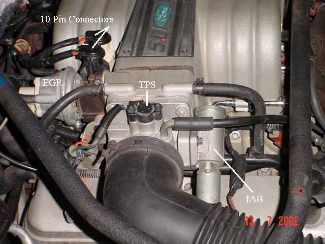
See the graphic for the location of the 10 pin connectors:
TPS_IAB_Pic.jpg


See the graphic for the 10 pin connector circuit layout.
harness02.gif
 
Figured it out. The main ground for the computer and chassis that is located next to the battery was broke. I didnt see it at first because it was behind the battery and the grounds were all cleaned up. Everythnig now works great. Got the car tuned finally.