|
Home > Articles/Tech > Mass Air Conversion |
|
Home > Articles/Tech > Mass Air Conversion |
| CONVERTING YOUR SPEED
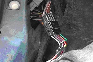
DENSITY 5.0 MUSTANG TO MASS AIR FLOW SYSTEM Author: Mike Stowe Mustang Mass Air Conversion In this document, I will outline the steps to convert a speed density mustang to the MAF system. I am generating this because I felt the documentation I had to work with could be improved. This is based on my own personal experience converting my 88LX convertible to MAF and the instructions that came with the kit I bought. The color codes of the wiring are what I saw in my car and may not be the same but probably are. This document is for reference only and I accept no responsibility for what you do to your car. REQUIRED COMPONENTS: You will need to obtain a Mass Air meter, a MAF computer and the electrical harness for the MAF meter. The meter harness can be purchased from several manufacturers for about 50-60 dollars but you can make your own if you wish. There are a few EEC's that can be used depending on the car. I've heard it doesn't matter manual vs. auto tranny but I don't know for sure so this is just some additional info for you. For older MAF computers, the numbers are: Manual transmission hard top:E9ZF 12A650 AA Manual transmission convertible:E9ZF 12A650 BA Automatic transimission:E9ZF 12A650 CA For later (early 90's I think) MAF computers, the numbers are: Automatic transimission:F3ZF 12A650 BA Manual transmission:F3ZF 12A650 AA Universal EEC:F3ZF 12A650 DA You can also use the 93 cobra computer:F3ZF 12A650 CA but it requires MAF calibrated for 24# injectors. The MAF mounting bracket and associated plumbing between the throttle body and the air filter box will have to be acquired from a junk yard or you can rig up your own setup. If you intend the to do the "optional" signals mentioned later, you'll also need to obtain 3 EEC connector pins and some wire. NOTES: Average mechanical skills are about all that is needed. The only special skill I suggest you have to do this conversion is soldering. Crimp connections are unreliable and could lead to future troubleshooting headaches which you should avoid. 1. EEC REMOVAL Before you begin, disconnect the battery. Remove the passenger side kick panel. There is 1 screw and a push-in fastener that secure it. Remove the screw in the white plastic retainer that holds the EEC in place. There was a ground wire and a relay, each one screw that I had to move out of the way so I could get the old EEC out. You should now be able to pull the EEC down and out. Once the EEC is out, remove the EEC harness connector using a 10mm socket to loosen the bolt in the center of the connector. 2. MAF HARNESS INSTALL You'll need to run the 4 wire MAF meter harness through the fire wall on the passenger side. I suggest you poke another hole in the large oval grommet the existing EEC harness goes through located in the upper corner on the passenger side of the firewall. I popped the grommet out of the firewall with a screwdriver and used an exacto to poke a hole in the thin section. You don't just want to blindly jam something through there because you may cut the insulation on some of the wires and cause future shorts. I then used a wire coat hanger as a snake, poking it through the grommet and coming out by the EEC inside the car. I taped the MAF meter harness to the snake (protecting the EEC pins) and pulled it through from inside the car. Pop the grommet back into the firewall after the harness has been pulled through. I then used some silicone to seal the area where the new harness goes through the grommet so I didn't get any water leaks. Remove the red "H" shaped plastic pin lock in the EEC connector. Gently pry around the plastic pin lock with a pointed awl or small scewdriver working it up and out of the connector. You can't add or remove EEC pins to the connector without removing this lock. Depending on the MAF meter you have, it may have a 4 or 5 pin connector. Refer below for pin locations.
Please note that the notches shown in the diagram are not the ones seen in the picture. The ones in the diagram are actually keys that only permit the connector to be installed into the EEC one way. Pins 20,40, and 60 are closest to you in the picture. It should be obvious because the pin locations for the additional signals must be empty.
3. MAF METER INSTALL
6. VEHICLE SPEED SENSOR SIGNALS
Congratulations! You should now be done with your
MAF conversion. I suggest you re-check all your wiring changes at this
point before you re-connect the battery to avoid a smoke show of a
different sort. Once you are happy that everything is correct, re-connect
the battery and start the car. The car may idle a bit rough for a while
until it relearns, but severe idle or drivability problems may indicate a
real problem. |