All Sensors Out Of Whack

Having a problem with my 93 GT 5.0 5spd. It's running poorly and i need some insight to a possible wiring problem.

Tried to run my KOEO test today and it wouldn't work so I had to run a wire from the battery ground straight to the STI trigger to get the test to start. Came back with these codes:
21 coolant temp sensor out of specified range
22 map sensor out of specified range
23 throttle position sensor out of range
34 EVP voltage above closed unit
67 Nuetral drive switch or circuit
81 Thermactor air circuit
82 Thermactor air circuit integrated controller circuit

Second set of codes were
22, 34, 51, 53, & 54 which are just more sensors out of range.
Am I right in assuming I have a broken signal return wire somewhere due to the fact that it connects to just about every problem I'm having right now. Codes and the KOEO test not wanting to start?
 
  • Sponsors (?)


All those dont return to the computer on the same wire...thats a lotta codes,....id consider borrowing a friends computer and see if thats not the issue
 
Fix the computer issue first and them all of the codes will go away...

Computer will not go into diagnostic mode on 91-93 model 5.0 Mustangs

How it is supposed to work:
The grey/red wire (pin 46) is signal ground for the computer. It provides a dedicated ground for the EGR, Baro, ACT, ECT, & TPS sensors as well as the ground to put the computer into self test mode. If this ground is bad, none of the sensors mentioned will work properly. That will severely affect the car's performance. You will have hard starting, low power and drivability problems. Since it is a dedicated ground, it passes through the computer on its way to the computer main power ground that terminates at the battery pigtail ground. It should read less than 1.5 ohms when measured from anyplace on the engine harness with the battery pigtail ground as the other reference point for the ohmmeter probe.

What sometimes happens is that the test connector grey/red wire gets jumpered to power which either burns up the wiring or burns the trace off the pc board inside the computer. That trace connects pins 46 to pins 40 & 60. Only an experienced electronics technician can open the computer up & repair the trace if it burns up and creates an open circuit.

The STI (Self Test Input ) is jumpered to ground to put the computer into test mode. Jumpering it to power can produce unknown results, including damage to the computer. The ohm test simply verifies that there are no breaks in the wiring between the test connector and the computer input.

How to test the wiring :
With the power off, measure the resistance between the computer test ground (grey/red wire) on the self test connector and battery ground. You should see less than 1.5 ohms.

attachment.php


If that check fails, remove the passenger side kick panel and disconnect the computer connector. There is a 10 MM bolt that holds it in place. Measure the resistance between the grey/red wire and pin 46 on the computer wiring connector : it should be less than 1.5 ohms. More that 1.5 ohms is a wiring problem. If it reads 1.5 ohms or less, then the computer is suspect. On the computer, measure the resistance between pin 46 and pins 40 & 60: it should be less than 1.5 ohms. More that that and the computer’s internal ground has failed, and the computer needs to be replaced.

See http://www.stangnet.com/mustang-forums/749974-computer-issue.html#post7490537 for Joel5.0’s fix for the computer internal signal ground.

If the first ground check was good, there are other wires to check. Measure the resistance between the STI computer self test connector (red/white wire) and pin 48 on the computer main connector: it should be less than 1.5 ohms. More that 1.5 ohms is a wiring problem

The following is a view from the computer side of the computer wiring connector: it is for an A9L, A9P computer.
eec04.gif


a9x-series-computer-connector-wire-side-view-gif.71316


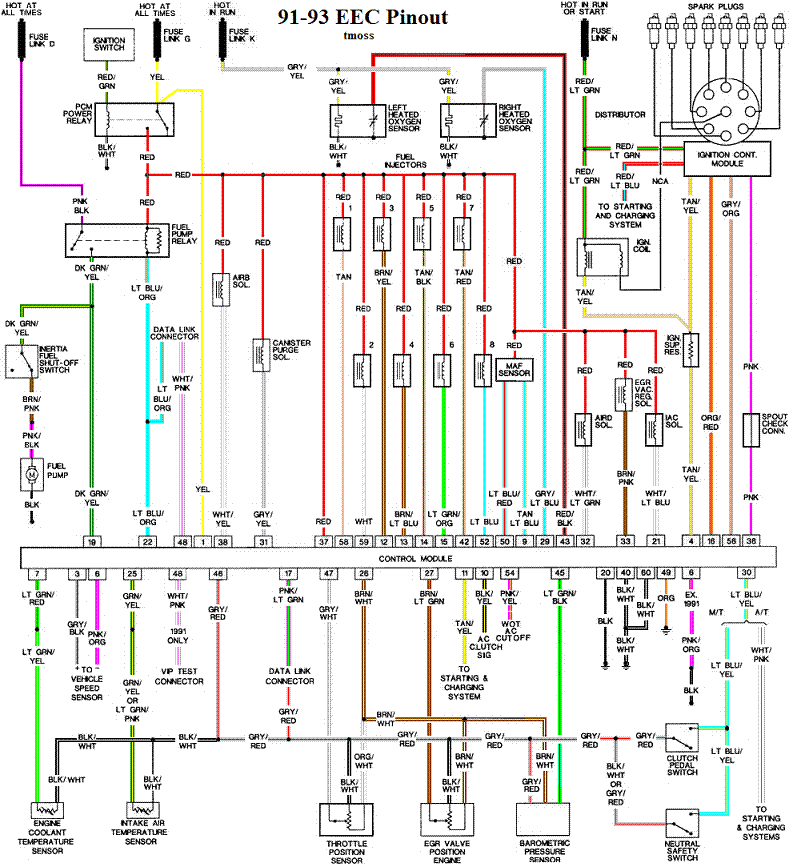
Diagram courtesy of Tmoss & Stang&2birds

Check out the diagram and notice all the places the grey/red wire goes. Almost every sensor on the engine except the MAF is connected to it.
91-93_5.0_EEC_Wiring_Diagram.gif


See the following website for some help from Tmoss (diagram designer) & Stang&2Birds
(website host) for help on 88-95 wiring http://www.veryuseful.com/mustang/tech/engine

See the graphic for the 10 pin connector circuit layout.
salt-pepper-10-pin-connectors-65-jpg.68512
 
Fix the computer issue first and them all of the codes will go away...

Computer will not go into diagnostic mode on 91-93 model 5.0 Mustangs

How it is supposed to work:
The grey/red wire (pin 46) is signal ground for the computer. It provides a dedicated ground for the EGR, Baro, ACT, ECT, & TPS sensors as well as the ground to put the computer into self test mode. If this ground is bad, none of the sensors mentioned will work properly. That will severely affect the car's performance. You will have hard starting, low power and drivability problems. Since it is a dedicated ground, it passes through the computer on its way to the computer main power ground that terminates at the battery pigtail ground. It should read less than 1.5 ohms when measured from anyplace on the engine harness with the battery pigtail ground as the other reference point for the ohmmeter probe.

What sometimes happens is that the test connector grey/red wire gets jumpered to power which either burns up the wiring or burns the trace off the pc board inside the computer. That trace connects pins 46 to pins 40 & 60. Only an experienced electronics technician can open the computer up & repair the trace if it burns up and creates an open circuit.

The STI (Self Test Input ) is jumpered to ground to put the computer into test mode. Jumpering it to power can produce unknown results, including damage to the computer. The ohm test simply verifies that there are no breaks in the wiring between the test connector and the computer input.

How to test the wiring :
With the power off, measure the resistance between the computer test ground (grey/red wire) on the self test connector and battery ground. You should see less than 1.5 ohms.

attachment.php


If that check fails, remove the passenger side kick panel and disconnect the computer connector. There is a 10 MM bolt that holds it in place. Measure the resistance between the grey/red wire and pin 46 on the computer wiring connector : it should be less than 1.5 ohms. More that 1.5 ohms is a wiring problem. If it reads 1.5 ohms or less, then the computer is suspect. On the computer, measure the resistance between pin 46 and pins 40 & 60: it should be less than 1.5 ohms. More that that and the computer’s internal ground has failed, and the computer needs to be replaced.

See http://www.stangnet.com/mustang-forums/749974-computer-issue.html#post7490537 for Joel5.0’s fix for the computer internal signal ground.

If the first ground check was good, there are other wires to check. Measure the resistance between the STI computer self test connector (red/white wire) and pin 48 on the computer main connector: it should be less than 1.5 ohms. More that 1.5 ohms is a wiring problem

The following is a view from the computer side of the computer wiring connector: it is for an A9L, A9P computer.
eec04.gif


a9x-series-computer-connector-wire-side-view-gif.71316


Diagram courtesy of Tmoss & Stang&2birds

Check out the diagram and notice all the places the grey/red wire goes. Almost every sensor on the engine except the MAF is connected to it.
91-93_5.0_EEC_Wiring_Diagram.gif


See the following website for some help from Tmoss (diagram designer) & Stang&2Birds
(website host) for help on 88-95 wiring http://www.veryuseful.com/mustang/tech/engine

See the graphic for the 10 pin connector circuit layout.
salt-pepper-10-pin-connectors-65-jpg.68512

LOL... were your ears burning?
 
Well like I said I think I have a wiring problem. Measured the ohms between the signal ground and the battery and it reads 665 ohms instead of 1.5.
Where should I start to troubleshoot and track down the broken wire or whatever it could be? I'm honestly about to swap out all my efi for a carb setup. This is getting ridiculous.

Don't butcher up a perfectly good car just because you don't understand how it works.

Check the batteries in you meter as a first step before doing anything else. They may be low, causing false readings.

Go back an reread my post. Disconnect the computer wiring harness, and measure the resistance between computer pin 46 and pins 40 or 60. It should be less than 1.5 ohms. More that that indicates a problem inside the computer. See http://www.stangnet.com/mustang-forums/749974-computer-issue.html#post7490537 for Joel5.0’s fix for the computer internal signal ground.