Wow! You guys have given me some great info and I'm excited to get out to the garage tomorrow to resume troubleshooting. A few updates from today's troubleshooting. First, everything works......everything, except the CEL stays illuminated. I decided to search the under dash and kick panel areas to make sure I did not forget any connectors after swapping to the T-5. I found three unconnected connectors. Unfortunately, one was for the rear window defogger (convertible, not equipped), the second was for the electric cooling fan for when the AC is turned on (2.3L's only) and the third was for the clutch/starter interlock (2.3L version). So, it appears all connectors that need to be connected are connected;
Remember, I did not have a CEL before the transmission swap, but I understand that I jiggled a lot of wires when I pulled the dash to replace pedal assys., etc. I did disconnect the battery, turn on the headlights, reconnect the battery and took the car on a 1/2 hour cruise at all speeds. When I returned home, I did an OBD ! code check for KOEO and got the following codes: 23-R, 34-R, 85-R, 22-R and 51-R. Note that I got "R" codes while running the test with the engine turned off and ignition on. Since I thought this was kinda funky, I turned off the ignition and tester, then turned them back on. This time, I got 23-O, 34-O, 85-O and 22-O. For continuous codes, I got 22-C, 35-C, 51-C and 53-C. The only thing I have replaced is the BAP sensor, but no improvement and I would rather not be a "parts hanger", especially if it turns out to be nothing more than a ground, etc.
One other item that might be worthwhile mentioning: To get my brand new OBD I tester to link to the ECU, I had to ground the single diagnostic lead to the negative post of the battery and the ground terminal of the tester as well. Otherwise the tester does not produce codes. Maybe this will trigger someone's memory of a similar situation.
Tomorrow, it's back out to the garage to take some readings with my VOM as suggested by NXCoupe, JRichker and all the others. Great to have a group of Foxbody enthusiasts to provide help when troubleshooting problems. Thanks to each of you and I hope that sometime I can return the favor!
MAP/BARO sensor operation and code 22
Revised 24 Oct 2018 add warning about trying to measure the MAP/BARO sensor output with a common multimeter.
On a Speed Density car, the MAP/BARO sensor is connected to the intake manifold and acts to sense the manifold pressure. Lower vacuum inside the intake manifold when combined with more throttle opening measured by the TPS means more airflow through the engine. As airflow increases, fuel flow through the injectors needs to increase to keep the air/fuel ratio where it needs to be. When manifold vacuum increases, the engine is either decelerating or idling, and it needs to reduce the fuel flow through the injectors.
On a Mass Air car, the MAP/BARO sensor vents to open air and actually senses the barometric pressure due to changes in weather and altitude. Its purpose is to set a baseline for the computer to know the barometric pressure. As barometric pressure decreases, it leans out the fuel flow to compensate for less oxygen in the air. When the barometric pressure rises, it increases to add fuel since there is more oxygen in the air. The fuel requirements decrease as altitude increases, since the atmospheric pressure decreases.
Disconnecting the wiring connector from the MAP or BARO sensor will set code 22..
Misconnecting the BARO sensor to vacuum on a Mass Air car will cause the computer to lean out the fuel mixture.
Code 22 or 126 MAP (vacuum) or BARO signal out of range. The MAP or BARO sensor is pretty much the same sensor for both Mass Air & Speed Density cars. The main difference is where it is connected. Mass Air cars vent it to the atmosphere, while Speed Density cars connect it to the intake manifold vacuum. Its purpose is to help set a baseline for the air/fuel mixture by sensing changes in barometric pressure. The MAP or BAP sensor puts out a 5 volt square wave that changes frequency with variations in atmospheric pressure. The base is 154 HZ at 29.92" of mercury - dry sunny day at sea level, about 68-72 degrees. You need an oscilloscope or frequency meter to measure it. There a very few DVM’s with a price tag under $40 that will measure frequency, but there are some out there.
Map sensor wiring:
black/white - ground
orange/white or +5 volts power
white/red signal out.
Measure the +5 volt supply using the orange/white and black/white wires
Measure the signal using the black/white and white/red wires.
The MAP/BARO sensor is mounted on the firewall behind the upper manifold on 86-93 Mustangs.
The Baro or MAP sensor can only be tested using a real frequency meter. The sensor output is a square wave which cannot be accurately measured with a common multimeter. Run the test key on, engine off.. The noise from the ignition system will likely upset the frequency meter. I used a 10 x oscilloscope probe connected from the frequency meter to the MAP/BAP to reduce the jitter in the meter's readout. And oscilloscope is very useful if you have access to one or know of someone who does. With an oscilloscope, you can see the waveform and amplitude.
If it is defective, your air/fuel ratio will be off and the car’s performance & emissions will suffer
Some basic checks you can make to be sure that the sensor is getting power & ground:
Note that all resistance tests must be done with power off. Measuring resistance with a circuit powered on will give false readings and possibly damage the meter.
Check the resistance between the black/white wire on the MAP/BARO sensor and then the black/white wire on the EGR and the same wire on the TPS. It should be less than 1 ohm. Next check the resistance between the black/white wire and the negative battery cable. It should be less than 1.5 ohm.
The following power on check requires you to turn the ignition switch to the Run position.
Use a DVM to check for 5 volts on the orange/white wire. If it is missing, look for +5 volts at the orange/white wire on the TPS or EGR sensors. Use the black/white wire for the ground for the DVM.
Code 23 - Throttle sensor out of range or throttle set too high - TPS needs to be reset to below 1.2 volts at idle. Keep in mind that when you turn the idle screw to set the idle speed, you change the TPS setting. [/b]
You'll need a Digital Voltmeter (DVM) to do the job.
Wire colors & functions:
Orange/white = 5 volt VREF from the computer
Dark Green/lt green = TPS output to computer
Black/white = Signal ground from computer
Always use the Dark Green/lt green & Black/white wires to set the TPS base voltage.
Do the test with the ignition switch in the Run position without the engine running.
Use the Orange/white & Black white wires to verify the TPS has the correct 5 volts source from the computer.
When you installed the sensor make sure you place it on the peg right and then tighten it down properly. Loosen the back screw a tiny bit so the sensor can pivot and loosen the front screw enough so you can move it just a little in very small increments. I wouldn’t try to adjust it using marks. Set it at .6.v-.9 v.
1. Always adjust the TPS and Idle with the engine at operating temp. Dive it around for a bit if you can and get it nice and warm.
2. When you probe the leads of the TPS, do not use an engine ground, put the ground probe into the lead of the TPS. You should be connecting both meter probes to the TPS and not one to the TPS and the other to ground.
If setting the TPS doesn’t fix the problem, then you may have wiring problems.
With the power off, measure the resistance between the black/white wire and battery ground. You should see less than 2 ohms. Check the same black /white wire on the TPS and MAP/Baro sensor. More than 1 ohm there and the wire is probably broken in the harness between the engine and the computer. The 10 pin connectors pass the black/white wire back to the computer, and can cause problems.
See the following website for some help from Tmoss (diagram designer) & Stang&2Birds (website host)
http://www.veryuseful.com/mustang/tech/engine/images/88-91eecPinout.gif
See the graphic for the 10 pin connector circuit layout.
Code 34 Or 334 - EGR voltage above closed limit –
Revised 26-Sep-2011 to add EGR cleaning and movement test for pintle when vacuum is applied to diaphragm
Failed sensor, carbon between EGR pintle valve and seat holding the valve off its seat. Remove the EGR valve and clean it with carbon remover. Prior to re-installing see if you can blow air through the flange side of the EGR by mouth. If it leaks, there is carbon stuck on the pintle valve seat clean or, replace the EGR valve ($85-$95).
Recommended procedure for cleaning the EGR:
Conventional cleaning methods like throttle body cleaner aren’t very effective. The best method is a soak type cleaner used for carburetors. If you are into fixing motorcycles, jet skis, snowmobiles or anything else with a small carburetor, you probably have used the one gallon soak cleaners like Gunk or Berryman. One of the two should be available at your local auto parts store for $22-$29. There is a basket to set the parts in while they are soaking. Soak the metal body in the carb cleaner overnight. Don’t immerse the diaphragm side, since the carb cleaner may damage the diaphragm. If you get any of the carb cleaner on the diaphragm, rinse it off with water immediately. Rinse the part off with water and blow it dry with compressed air. Once it has dried, try blowing through the either hole and it should block the air flow. Do not put parts with water on them or in them in the carb cleaner. If you do, it will weaken the carb cleaner and it won’t clean as effectively.
Gunk Dip type carb & parts soaker:
If you have a handy vacuum source, apply it to the diaphragm and watch to see if the pintle moves freely. Try blowing air through either side and make sure it flows when the pintle retracts and blocks when the pintle is seated. If it does not, replace the EGR.
If the blow by test passes, and you have replaced the sensor, then you have electrical ground problems. Check the resistance between the black/white wire on the MAP/BARO sensor and then the black/white wire on the EGR and the same wire on the TPS. It should be less than 1.5 ohm. Next check the resistance between the black/white wire and the negative battery post. It should be less than 1.5 ohm.
Note that all resistance tests must be done with power off. Measuring resistance with a circuit powered on will give false readings and possibly damage the meter.
Let’s put on our Inspector Gadget propeller head beanies and think about how this works:
The EGR sensor is a variable resistor with ground on one leg and Vref (5 volts) on the other. Its’ resistance ranges from 4000 to 5500 Ohms measured between Vref & ground, depending on the sensor. The center connection of the variable resistor is the slider that moves in response to the amount of vacuum applied. The slider has some minimum value of resistance greater than 100 ohms so that the computer always sees a voltage present at its’ input. If the value was 0 ohms, there would be no voltage output. Then the computer would not be able to distinguish between a properly functioning sensor and one that had a broken wire or bad connection. The EGR I have in hand reads 700 Ohms between the slider (EPV) and ground (SIG RTN) at rest with no vacuum applied. The EGR valve or sensor may cause the voltage to be above closed limits due to the manufacturing tolerances that cause the EGR sensor to rest at a higher position than it should.
The following sensors are connected to the white 10 pin connector (salt & pepper engine harness connectors)
This will affect idle quality by diluting the intake air charge
Code 51 Engine Coolant Temperature (ECT) sensor signal is/was too high -
[color= blue]Revised 6-Apr-2017 to add diagrams and resistance check for ECT wiring.[/color]
Possible bad ECT sensor or wiring. Possible missing signal ground – black/wire broken or bad connection. With the power off, measure the resistance between the black/white wire and battery ground. You should see less than 1 ohm. Check the same black /white wire on the TPS and MAP sensor. More than 1 ohm there and the wire is probably broken in the harness between the engine and the computer. The 10 pin connectors pass the black/white wire back to the computer, and can cause problems.
The computer Engine Coolant Temperature sensor has absolutely nothing to do with the temperature gauge. They are different animals. The ECT sensor is normally located it the passenger side front of the engine in the water feed tubes for the heater. It has two wires that connect by a weathertight plastic connector.
The water temperature sender for the temp gauge is located in the driver's side lower intake manifold. It has a single wire that connects by a push on connector on the temp sender.
If you have replaced the ECT sensor and are still having ECT like problem symptoms, check the ECT wiring .
See the graphic for the 10 pin connector circuit layout.
Check the resistance of the green wire on the ECT connector to the green wire on pin 7 of the computer connector. You should see less that 1 Ω (ohm)
Use Pin 46 on the computer for ground for both ECT & ACT tests to get most accurate readings.
Pin 7 on the computer - ECT signal in. At 176 degrees F it should be .80 volts
Pin 25 on the computer - ACT signal in. At 50 degrees F it should be 3.5 volts. It is a good number if the ACT is mounted in the inlet airbox. If it is mounted in the lower intake manifold, the voltage readings will be lower because of the heat transfer.
50 degrees F = 3.52 v
68 degrees F = 3.02 v
86 degrees F = 2.62 v
104 degrees F = 2.16 v
122 degrees F = 1.72 v
140 degrees F = 1.35 v
158 degrees F = 1.04 v
176 degrees F = .80 v
194 degrees F = .61
212 degrees F = .47 v
230 degrees F = .36 v
248 degrees F = .28 v
Ohms measures at the computer with the computer disconnected, or at the sensor with the sensor disconnected.
50 degrees F = 58.75 K ohms
68 degrees F = 37.30 K ohms
86 degrees F = 27.27 K ohms
104 degrees F = 16.15 K ohms
122 degrees F = 10.97 K ohms
140 degrees F = 7.60 K ohms
158 degrees F = 5.37 K ohms
176 degrees F = 3.84 K ohms
194 degrees F = 2.80 K ohms
212 degrees F = 2.07 K ohms
230 degrees F = 1.55 K ohms
248 degrees F = 1.18 k ohms
The code 85 is an odd duck and can be put off until you get the current string of codes resolved. I am including it for sake of completeness.
Code 85 CANP solenoid - The Carbon Canister solenoid is inoperative or missing.
Revised 11 –Jan_2015 to add warning about vacuum leaks due to deteriorated hose or missing caps on vacuum lines when the solenoid is removed.
Check vacuum lines for leaks and cracks. Check electrical wiring for loose connections, damaged wiring and insulation. Check solenoid valve operation by grounding the gray/yellow wire to the solenoid and blowing through it.
The computer provides the ground for the solenoid. The red wire to the solenoid is always energized any time the ignition switch is in the run position.
If you disconnected the carbon canister and failed to properly cap the vacuum line coming from under the upper intake manifold, you will have problems. You will also have problems if the remaining hose coming from under the upper intake manifold or caps for the vacuum line are sucking air.
Charcoal canister plumbing - one 3/8" tube from the bottom of the upper manifold to the rubber hose. Rubber hose connects to one side of the canister solenoid valve. Other side of the solenoid valve connects to one side of the canister. The other side of the canister connects to a rubber hose that connects to a line that goes all the way back to the gas tank. There is an electrical connector coming from the passenger side injector harness near #1 injector that plugs into the canister solenoid valve. It's purpose is to vent the gas tank. The solenoid valve opens at cruse to provide some extra fuel. The canister is normally mounted on the passenger side frame rail near the smog pump pulley.
Connecting the gas tank vent line directly to the intake manifold will result in fuel vapor being constantly sucked into the intake manifold. There is unmetered fuel that the computer cannot adjust for. The result is poor idle and poor fuel economy.
It does not weigh but a pound or so and helps richen up the cruse mixture. It draws no HP & keeps the car from smelling like gasoline in a closed garage. So with all these good things and no bad ones, why not hook it up & use it?
The purge valve solenoid connector is a dangling wire that is near the ECT sensor and oil filler on the passenger side rocker cover. The actual solenoid valve is down next to the carbon canister. There is about 12"-16" of wire that runs parallel to the canister vent hose that comes off the bottom side of the upper intake manifold. That hose connects one port of the solenoid valve; the other port connects to the carbon canister.
The purge valve solenoid should be available at your local auto parts store.
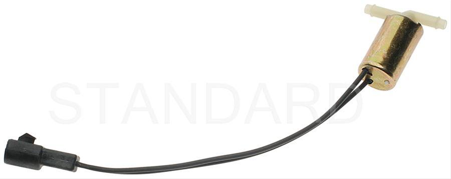
Purge valve solenoid:
The carbon canister is normally mounted on the passenger side frame rail near the smog pump pulley.
Carbon Canister:
All the codes except the code 85 point to an open circuit on the sensor signal ground circuit. The fact that you had to jumper the computer diagnostic input wire directly to battery ground to get the codes to dump confirms this diagnosis,
If you don't own a Multimeter or DVM or don't know how to properly use the one you have, you will need some one on one help from someone who knows how to correctly use your meter.
Troubleshooting loss of signal ground on pin 46 for 86-90 model 5.0 Mustangs.
Revised Sep-22-2019 to add back probing the connections to test the TPS voltages
A fault in the TPS circuit where the voltage goes above. 4.3 volts at idle can shut off the injectors.
TPS adjustment:
You need to do the testing with the TPS sensor plugged in as it would normally be when the engine is running. Use some safety pins to probe the connector from the back side to make contact with the wires,
Wire colors & functions:
Orange/white = 5 volt VREF from the computer
Dark Green/lt green = TPS output to computer
Black/white = Signal ground from computer
Always use the Dark green/lt green & Black/white wires to set the TPS base voltage; anywhere from.5 to 1.0 volt is OK
Do the test with the ignition switch in the Run position without the engine running.
Use the Orange/white & Black white wires to verify the TPS has the correct 5 volts source from the computer.
Adjusting the TPS fails to resolve the problem:
If the adjustment does not work to get the voltage below 1 volt, you probably have a bad signal ground. The black/white wire is computer pin 46 and is signal ground for many things. If it burns up inside the computer you get multiple faults and cannot pull codes.
Disconnect the positive battery cable to insure correct results when measuring the resistance of grounds. The small voltage drop that is often in a circuit can cause erroneous readings. Since the computer and several other things still draw current even with the ignition switch in the Off position, this is a necessary step.
Check the black/white wire resistance. Connect one ohmmeter lead to the black/white wire on the TPS and one lead to the negative post on the battery. You should see less than 1.5 Ω; more than that indicates a problem. Always take resistance measurements with the circuit powered off.
Check the resistance of the black/white signal ground on the MAP/BARO sensor on the firewall behind the upper intake manifold. The resistance should be less than 1.5 Ω If the resistance value of the black/white signal ground on the MAP/BARO is1.5 Ω and the TPS is higher or doesn't read at all, then there is a problem in the engine mounted fuel injection harness or the 10 pin connector
Clean the 10 pin salt & pepper shaker connectors.
Diagram courtesy of Tmoss & Stang&2birds
See the graphic for the 10 pin connector circuit layout.
The injector power pin is the VPWR pin in the black 10 pin connector. [/b]
How it is supposed to work:
The black/white wire (computer pin 46) is signal ground for the computer. It provides a dedicated ground for the EGR, Baro, ACT, ECT, & TPS sensors as well as the ground to put the computer into self test mode. Since it is a dedicated ground, it passes through the computer on its way to the computer main power ground that terminates at the battery pigtail ground. It should read less than 1.5 Ω when measured from anyplace on the engine harness with the battery pigtail ground as the other reference point for the ohmmeter probe. What sometimes happens is that it gets jumpered to power which either burns up the wiring or burns the trace off the pc board inside the computer. That trace connects pins 46 to pins 40 & 60, which are power ground for the computer.
See the pictures below for help finding and fixing the burnt computer trace.
The fix is some careful soldering of a small jumper wire across the burnt section of copper trace.
How to test the wiring:
Disconnect the positive battery cable to insure correct results when measuring the resistance of grounds. The small voltage drop that often in a circuit can cause erroneous readings. Since the computer and several other things still draw current even with the ignition switch in the Off position, this is a necessary step.
With the power off, measure the resistance between the computer test ground (black/white wire) on the self-test connector and battery ground. You should see less than 1.5 Ω
If that check fails, remove the passenger side kick panel and disconnect the computer connector. There is a 10 MM bolt that holds it in place. Measure the resistance between the black/white wire and pin 46: it should be less than 1.5 ohms. More than 1.5 ohms is a wiring problem. If it reads 1.5 ohms or less, then the computer is suspect. On the computer, measure the resistance between pin 46 and pins 40 & 60: it should be less than 1.5 ohms. More than that and the computer’s internal ground has failed, and the computer needs to be repaired or replaced.
Measure the resistance between the black/white wire on each of the following sensors: TPS, ECT, ACT and EGR. If you find one that is greater than 1.5 Ω, measure between that sensor and pin #1 of the white 10 pin connectors. Pin #1 is the center pin and is labeled sig-rtrn on the diagram
The possible cause for an open circuit and the burned signal ground trace in the computer is a mismatch between the O2 sensor wiring harness and the computer.
@Mustang5L5 please provide a sanity/clarity check to insure that I didn't miss anything in the O2 sensor harness modification
O2 Sensor harness interchange and modification
Originally Posted by 302EFI [/b]
Revised 16-Oct-2011 to add O2 sensor harness warnings
The wires for the 02's and low oil did not change throughout the years, they are all in the same place.
The main ones you need to worry about are (on the harness end (ECU) that plugs into the 02 plug) is:
\- 1. Lightblue / yellow
- 2. White / Purple
- 3. Purple / Yellow
The White/Purple & Purple/Yellow gets looped for a automatic ECU
The Purple/Yellow & Lightblue/Yellow for a manual ECU
Not all wires are shown for clarity and simplicity
See
http://forums.corral.net/forums/gen...manual-auto-differences-year-differences.html for more O2 sensor wiring harness info
Basic premise to use with transmission swaps:
Only run a 5 speed trans O2 harness with an A9L. Do not run an Auto O2 sensor harness with an A9L. Doing so will damage the computer’s internal signal ground.
Only run an Auto trans O2 sensor harness with an A9P in a car that has an Auto trans. Using a 5 speed trans O2 sensor harness with an Auto trans will cause no crank problems.
See http://www.stangnet.com/mustang-forums/749974-computer-issue.html#post7490537 for Joel5.0’s fix to the computer internal signal ground.
The 4 cylinder O2 harness uses 4 wire O2 sensors. It probably won’t work correctly without modifying it.
See the following website for some help from Tmoss (diagram designer) & Stang&2Birds (website host) for help on 88-95 wiring;
http://www.veryuseful.com/mustang/tech/engine/ Everyone should bookmark this site.[/b]
TFI module wiring for 94-95 Mustang GT
http://www.veryuseful.com/mustang/tech/engine/images/Mustang-94-95-IgnitionControlModule.gif
Complete computer, actuator & sensor wiring diagram for 94-95 Mustangs
Complete computer, actuator & sensor wiring diagram for 91-93 Mass Air Mustangs
Complete computer, actuator & sensor wiring diagram for 88-90 Mass Air Mustangs
5.0 wiring diagram for Fuel Injectors, Sensors, and Actuators
Main body EFI wiring harness
Ignition switch wiring
O2 sensor wiring harness
Vacuum diagram 89-93 Mustangs
HVAC vacuum diagram
TFI module differences & pin out
Fuse box layout
Mustang 5.0 Lights and Radio schematic, by TMoss:
http://www.veryuseful.com/mustang/tech/engine/images/mustangFoxLights-Radio_diag.gif
87-92 power window wiring
93 power window wiring
T5 Cutaway showing T5 internal parts
Visual comparison of the Ford Fuel Injectors, picture by TMoss:
Convertible top motor wiring
http://www.veryuseful.com/mustang/tech/engine/images/mustang88VertTopMotorCkt.gif
Engine mounted fuel injector harness
Location of the TPS, IAB, and the 10-pin connectors on a 5.0, picture by TMoss:
Starter circuit
Alternator diagram for 94-95 Mustangs.

 Any thoughts on how to attack? Will a manual trans. powertrain control module help? Is it just coincidence that I now have a check engine light after the swap or something that someone else has run into?
 KOEO): 24-O, 85-O, 22-O, 23-O and 34-O plus 22-C, 35-C, 51-C, 53-C and 54-C. It actually pulled the codes in that order (out of numerical sequence), naturally, with a 10 between the O-codes and C-codes. If you're the "General Karthief", I'm going to leave this thing parked in the street tonight with the key in the ignition for you!