
Looking for some assistance troubleshooting my bad A9L. I had a running driving speed density 87 car with the stock ECM. Not only did the engine have a bearing on the way out but the ECM ran the fuel pump all the time. I have since swapped the engine, converted to MAF, and installed an A9L. The car ran for a good 10 min or so but I was getting 5v on the TPS green wire while I was trying to set it. After trying to assess why I had 5v there I decided to pull the ECM and I can see the pin 46 trace wire burnt. I'm trying to figure out what to do next? I can fix the trace on the board, but what causes this? I don't see any visual signs of capacitors damaged. Was it just a bad ECM? I have my neutral safety switch jumped out but I have a new one in route. I don't think that could cause this? I have heard about checking for voltage at pin 46 without the ECM installed so I will try that next. Any other things I should check or look for? Oddly the car ran fine as a speed density car with an engine knock lol. Now I can't seem to get it going. TIA.
You are using an out of date browser. It may not display this or other websites correctly.
You should upgrade or use an alternative browser.
You should upgrade or use an alternative browser.
Electrical ECM Pin 46 Trace Wire Burnt on MAF Conversion
- Thread starter Scottryan86
- Start date
-
Sponsors (?)
Yes, I had to splice in the red and black wire from the MAF harness, then add the two other wires into the harness pin locations, and move/repin two existing wires.Don't you have to swap pins on the old SD ECU wire harness for a MAF conversion.
HemiRick
I'd be looking at jacking under the house
That trace gets burnt when O2 wiring isn't right, if you're convinced its now right, just jumper the bad section of trace with a piece of wire and some solder.
My 87 should have the right harnesses assuming it was always a 5 speed car. Wouldn’t hurt to double check I supposeThat trace gets burnt when O2 wiring isn't right, if you're convinced its now right, just jumper the bad section of trace with a piece of wire and some solder.
87 doesn’t have an 02 jumper. Test for voltage on pin 46 during key on and during crank. Shouldn’t be any.

In the meantime send the ecu to ecuexchange, you can find them on ebay or google it. They will fix the trace and upgrade capacitors if needed, then you know it done rite.
HemiRick
I'd be looking at jacking under the house
working on these old ECU printed circuit boards is easy....the only trick is they are coated in a rubberized coating that has to be scraped off wherever you plan on working as the 1st step. An exacto blade works great for this....
I fixed that burnt trace wire and checked for voltage on pin 46 and that was ok. I also had .95v at the TPS which was previously reading 5v. The car started right up and idled good. Ran it for 10 minutes or so, drive it quickly down the street and back, then it started to idle up and stick at 1500 rpm or so. I shut it down. I can't pull codes again. The TPS still says .95 so it is not doing the same as before. Still something seems wrong though. Could there be other issues with the ECU? Should I just send the whole ECU out to ecuexchange as General said?
How did the capacitors look? We’re they greenish at the bases or did they still look clean?
do you still have continuity between pin 46 and 40&60?
pretty sure I’m following you on IG too btw
do you still have continuity between pin 46 and 40&60?
pretty sure I’m following you on IG too btw
How did the capacitors look? We’re they greenish at the bases or did they still look clean?
do you still have continuity between pin 46 and 40&60?
pretty sure I’m following you on I
do you still have continuity between pin 46 and 40&60?
pretty sure I’m following you on I
I'll check for continuity, I haven't done that yet. The caps looked fine, no color or swelling that was visual. So you've probably seen this mess of a car on @project_saleen_clones huh? lolHow did the capacitors look? We’re they greenish at the bases or did they still look clean?
do you still have continuity between pin 46 and 40&60?
pretty sure I’m following you on IG too btw

I don’t have any continuity between 46 and 40 or 46 and 60?Yup. I’ve seen it. I’m @maverick9d
Found a short on a green wire where it goes through the firewall. Put a different A9L in and fixed the short. Car runs, .95 at TPS, still can’t run the code reader though?
Computer will not go into diagnostic mode on 86-90 models 5.0 Mustangs .
Revised 23 May 2020 to include warning about jumpering the dark brown connector with a black/orange wire.(12 volts) to the test connector.
Disconnect the battery positive terminal before making any resistance checks.
The voltage drop in the ground cable will cause incorrect resistance readings.
How it is supposed to work:
The black/white wire (pin 46) is signal ground for the computer. It provides a dedicated ground for the EGR, Baro, ACT, ECT, & TPS sensors as well as the ground to put the computer into self test mode. If this ground is bad, none of the sensors mentioned will work properly. That will severely affect the car's performance. You will have hard starting, low power and drivability problems. Since it is a dedicated ground, it passes through the computer on its way to the computer main power ground that terminates at the battery pigtail ground. It should read less than 1.5 ohms when measured from any signal ground on the engine mounted fuel injector harness with the battery pigtail ground as the other reference point for the ohmmeter probe.
Engine mounted fuel injector wiring harness sensors for a 5.0 mustang

What sometimes happens is that the test connector black/white wire gets jumpered to power which either burns up the wiring or burns the trace off the pc board inside the computer. That trace connects pins 46 to pins 40 & 60.
WARNING!!! There is a single dark brown connector with a black/orange wire. It is the 12 volt power to the under the hood light. Do not jumper it to the computer test connector. If you do, you will damage the computer.
OR
If an O2 sensor harness from an automatic transmission Mustang is used with an A9L manual shift transmission computer. The 12 volts from the automatic transmission starter circuit will damage the A9L computer.
The STI (Self Test Input) is jumpered to ground to put the computer into test mode. Jumpering it to power can produce unknown results, including damage to the computer. The ohm test simply verifies that there are no breaks in the wiring between the test connector and the computer input.
How to test the wiring:
With the power off, measure the resistance between the computer test ground (black/white wire) on the self test connector and battery ground. You should see less than 1.5 ohms.
If that check fails, remove the passenger side kick panel and disconnect the computer connector. There is a 10 MM bolt that holds it in place. Measure the resistance between the black/white wire and pin 46 on the computer wiring connector: it should be less than 1.5 ohms. More than 1.5 ohms is a wiring problem. If it reads 1.5 ohms or less, then the computer is suspect. On the computer, measure the resistance between pin 46 and pins 40 & 60: it should be less than 1.5 ohms. More than that and the computer’s internal ground has failed, and the computer needs to be repaired or replaced.
While you have the computer connector disconnected from the computer, turn the ignition switch to the Start position and look for 12 volts on pin 46 of the computer wiring harness. If you see 12 volts then you have an automatic transmission O2 sensor harness. That will damage the A9L manual shift transmission computer.
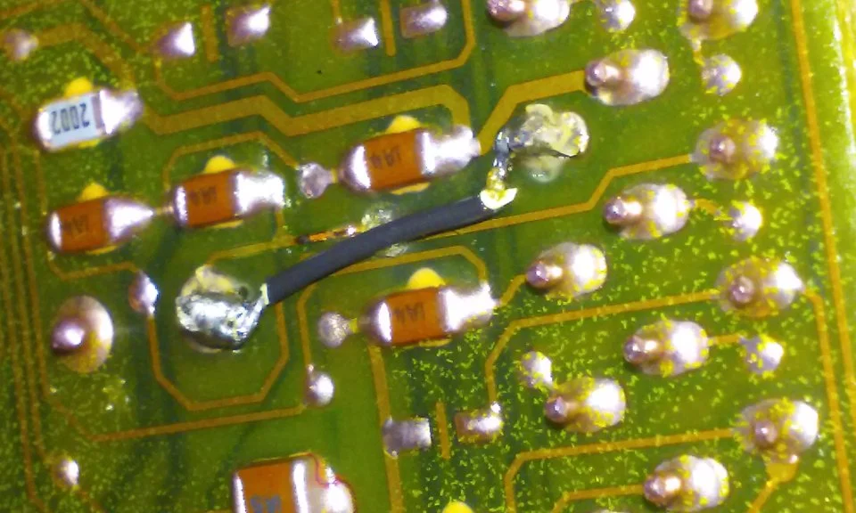
See the pictures below for help finding and fixing the burnt computer trace.

The fix is some careful soldering of a small jumper wire across the burnt section of copper trace.
If the first ground check was good, there are other wires to check. Measure the resistance between the STI computer self test connector (red/white wire) and pin 48 on the computer main connector: it should be less than 1.5 ohms. More than 1.5 ohms is a wiring problem
The following is a view from the computer side of the computer wiring connector: it is for an A9L, A9P computer.


Diagram courtesy of Tmoss & Stang&2birds
Check out the diagram and notice all the places the black/white wire goes. Almost every sensor on the engine except the MAF is connected to it.

See the following website for some help from Tmoss (diagram designer) & Stang&2Birds
(website host) for help on 88-95 wiring http://www.veryuseful.com/mustang/tech/engine
See the graphic for the 10 pin connector circuit layout.

Revised 23 May 2020 to include warning about jumpering the dark brown connector with a black/orange wire.(12 volts) to the test connector.
Disconnect the battery positive terminal before making any resistance checks.
The voltage drop in the ground cable will cause incorrect resistance readings.
How it is supposed to work:
The black/white wire (pin 46) is signal ground for the computer. It provides a dedicated ground for the EGR, Baro, ACT, ECT, & TPS sensors as well as the ground to put the computer into self test mode. If this ground is bad, none of the sensors mentioned will work properly. That will severely affect the car's performance. You will have hard starting, low power and drivability problems. Since it is a dedicated ground, it passes through the computer on its way to the computer main power ground that terminates at the battery pigtail ground. It should read less than 1.5 ohms when measured from any signal ground on the engine mounted fuel injector harness with the battery pigtail ground as the other reference point for the ohmmeter probe.
Engine mounted fuel injector wiring harness sensors for a 5.0 mustang
What sometimes happens is that the test connector black/white wire gets jumpered to power which either burns up the wiring or burns the trace off the pc board inside the computer. That trace connects pins 46 to pins 40 & 60.
WARNING!!! There is a single dark brown connector with a black/orange wire. It is the 12 volt power to the under the hood light. Do not jumper it to the computer test connector. If you do, you will damage the computer.
OR
If an O2 sensor harness from an automatic transmission Mustang is used with an A9L manual shift transmission computer. The 12 volts from the automatic transmission starter circuit will damage the A9L computer.
The STI (Self Test Input) is jumpered to ground to put the computer into test mode. Jumpering it to power can produce unknown results, including damage to the computer. The ohm test simply verifies that there are no breaks in the wiring between the test connector and the computer input.
How to test the wiring:
With the power off, measure the resistance between the computer test ground (black/white wire) on the self test connector and battery ground. You should see less than 1.5 ohms.
If that check fails, remove the passenger side kick panel and disconnect the computer connector. There is a 10 MM bolt that holds it in place. Measure the resistance between the black/white wire and pin 46 on the computer wiring connector: it should be less than 1.5 ohms. More than 1.5 ohms is a wiring problem. If it reads 1.5 ohms or less, then the computer is suspect. On the computer, measure the resistance between pin 46 and pins 40 & 60: it should be less than 1.5 ohms. More than that and the computer’s internal ground has failed, and the computer needs to be repaired or replaced.
While you have the computer connector disconnected from the computer, turn the ignition switch to the Start position and look for 12 volts on pin 46 of the computer wiring harness. If you see 12 volts then you have an automatic transmission O2 sensor harness. That will damage the A9L manual shift transmission computer.
See the pictures below for help finding and fixing the burnt computer trace.
The fix is some careful soldering of a small jumper wire across the burnt section of copper trace.
If the first ground check was good, there are other wires to check. Measure the resistance between the STI computer self test connector (red/white wire) and pin 48 on the computer main connector: it should be less than 1.5 ohms. More than 1.5 ohms is a wiring problem
The following is a view from the computer side of the computer wiring connector: it is for an A9L, A9P computer.
Diagram courtesy of Tmoss & Stang&2birds
Check out the diagram and notice all the places the black/white wire goes. Almost every sensor on the engine except the MAF is connected to it.
See the following website for some help from Tmoss (diagram designer) & Stang&2Birds
(website host) for help on 88-95 wiring http://www.veryuseful.com/mustang/tech/engine
See the graphic for the 10 pin connector circuit layout.
I am having this same issue. My trace is burnt in the exact same spot and I cannot pull codes. The only difference is that I have an a9p because I’m automatic. The trace fix is easy but how should I find the cause of the short? Has anyone been able to troubleshoot the cause of this burnt trace?
Similar threads
- Replies
- 5
- Views
- 1K
- Replies
- 26
- Views
- 1K
- Replies
- 11
- Views
- 2K
- Replies
- 14
- Views
- 3K