High NO - high combustion temps - retard timing, check EGR for operation.
EGR System theory and testing
The EGR shuts off at Wide Open Throttle (WOT), so it has minimal effect on performance. The addition of exhaust gas drops combustion temperature, increases gas mileage and reduces the tendency of the engine to ping. It can also reduce HC emissions by reducing fuel consumption. The primary result of EGR usage is a reduction in NOx emissions.
The EGR system has a vacuum source (line from the intake manifold) that goes to the EVR, computer operated electronic vacuum regulator. The EVR is located on the back of the passenger side shock strut tower. The computer uses RPM, Load. and some other factors to tell the EVR to pass vacuum to open the EGR valve. The EGR valve and the passages in the heads and intake manifold route exhaust gas to the EGR spacer (throttle body spacer). The EGR sensor tells the computer how far the EGR valve is open. Then computer adjusts the signal sent to the EVR to hold, increase or decrease the vacuum. The computer adds spark advance to compensate for the recirculated gases and the slower rate they burn at.
Troubleshooting:
There should be no vacuum at the EGR valve when at idle. If there is, the EVR (electronic vacuum regulator) mounted on the backside of the passenger side wheelwell is suspect. Check the vacuum line plumbing to make sure the previous owner didn’t cross the vacuum lines.
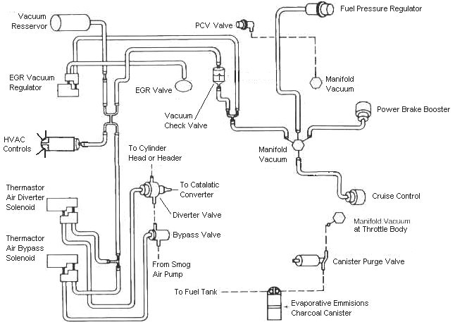
Diagram courtesy of Tmoss & Stang&2birds. (the diagram says 88 GT, but the EGR part is the same for 86-93 Mustangs)
The EGR sensor is basically a variable resistor, like the volume control on a radio. One end is 5 volt VREF power from the computer (red/orange wire). One end is computer signal ground (black/white), and the middle wire (brown/lt green) is the signal output from the EGR sensor. It is designed to always have some small voltage output from it anytime the ignition switch is the Run position. That way the computer knows the sensor & the wiring is OK. No voltage on computer pin 27 (brown/lt green wire) and the computer thinks the sensor is bad or the wire is broken and sets code 31. The voltage output can range from approximately .6-.85 volt.
The EVR regulates vacuum to the EGR valve to maintain the correct amount of vacuum. The solenoid coil should measure 20-70 Ohms resistance. The regulator has a vacuum feed on the bottom which draws from the intake manifold. The other vacuum line is regulated vacuum going to the EGR valve. One side of the EVR electrical circuit is +12 volts anytime the ignition switch is in the run position. The other side of the electrical circuit is the ground path and is controlled by the computer. The computer switches the ground on and off to control the regulator solenoid.
EGR test procedure courtesy of cjones
EGR test procedure courtesy of cjones
to check the EGR valve:
bring the engine to normal temp.
connect a vacuum pump to the EGR Valve or
see the EGR test jig drawing below. Connnect the test jig or to directly to manifold vacuum.
Do not connect the EGR test jig to the EVR (Electronic Vacuum Regulator).
apply 5in vacuum to the valve.
Using the test jig, use your finger to vary the vacuum
if engine stumbled or died then EGR Valve and passage(there is a passageway through the heads and intake) are good.
if engine did NOT stumble or die then either the EGR Valve is bad and/or the passage is blocked.
if engine stumbled,
connect EGR test jig to the hose coming off of the EGR Valve.
Use your finger to cap the open port on the vacuum tee.
snap throttle to 2500 RPM (remember snap the throttle don't hold it there).
did the vacuum gauge show about 2-5 in vacuum?
if not the EVR has failed
EGR test jig
To test the computer and wiring to the computer, you can use a test light across the EVR wiring connectors and dump the codes. When you dump the codes, the computer does a self test that toggles every relay/actuator/solenoid on and off. When this happens, the test light will flicker. If the test light remains on the computer or the wiring is suspect.
To check the EVR to computer wiring, disconnect the EVR connector and connect one end of the Ohmmeter to the dark green wire EVR wiring. Remove the passenger side kick panel and use a 10 MM socket to remove the computer connector from the computer. Set the Ohmmeter to high range and connect the other ohmmeter lead to ground. You should see an infinite open circuit indication or a reading greater than 1 Meg Ohm. If you see less than 200 Ohms, the dark green wire has shorted to ground somewhere.
Late Model Restoration may still have the Ford Racing M-12071-N302 kit with the EGR valve & sensor along with the ACT & ECT sensors for $45. See
http://www.latemodelrestoration.com/iwwida.pvx?;item?item_no=M12071N302 1&comp=LRS for more details
High HC – Lean misfire, vacuum leak, common misfire due to worn or weak ignition system components. On rare occasions, an overly rich mixture may be the cause. Do the ethanol/E85 fill up as suggested.
Check spark plugs, spark plug wires & distributor cap for damage or loose connections.
Do a cylinder balance test to spot weak or misfiring cylinders. Replace PVC valve, grommet & clean screen that is below the PVC grommet.
Inspect
all the vacuum lines, looking for small cracks and damage. Be prepared to replace any broken or damaged line you find.
b]Diagram courtesy of Tmoss & Stang&2birds[/b]
Check fuel pressure:
The local auto parts store may rent or loan a fuel pressure test gauge if you don't have one.
Disconnect vacuum line and check it for evidence of fuel present on the line. If you find fuel, the fuel pressure regulator has failed. Cap the vacuum line and stow it out of the way.
Connect fuel pressure test gauge to Schrader port located just behind the alternator.
Turn the ignition switch on & start the engine. Observe the pressure : you should see 37-41 PSI at idle.
Turn the ignition off, reconnect the vacuum line and disconnect the fuel pressure test gauge. Watch out for squirting gas when you do this.
Cylinder balance test:
The computer has a cylinder balance test that helps locate cylinder with low power output. You’ll need to dump the codes out of the computer and make sure that you have the A/C off, and the transmission in neutral. Fail to do this and you can’t do the engine running dump codes test that allows you to do the cylinder balance test.
Here's the way to dump the computer codes with only a jumper wire or paper clip and the check engine light, or test light or voltmeter. I’ve used it for years, and it works great. You watch the flashing test lamp or Check Engine Light and count the flashes.
Be sure to turn off the A/C, and put the transmission in neutral when dumping the codes. Fail to do this and you will generate a code 67 and not be able to dump the Engine Running codes.
Here's the link to dump the computer codes with only a jumper wire or paper clip and the check engine light, or test light or voltmeter. I’ve used it for years, and it works great. You watch the flashing test lamp or Check Engine Light and count the flashes.
See
Troublcodes.net Trouble Codes OBD & OBD2 Trouble Codes and Technical info & Tool Store. By BAT Auto Technical
If your car is an 86-88 stang, you'll have to use the test lamp or voltmeter method. There is no functional check engine light on the 86-88's except possibly the Cali Mass Air cars.
The STI has a gray connector shell and a white/red wire. It comes from the same bundle of wires as the self test connector.
89 through 95 cars have a working Check Engine light. Watch it instead of using a test lamp.
The STI has a gray connector shell and a white/red wire. It comes from the same bundle of wires as the self test connector.
WARNING!!! There is a single dark brown connector with a black/orange wire. It is the 12 volt power to the under the hood light. Do not jumper it to the computer test connector. If you do, you will damage the computer.
What to expect:
You should get a code 11 (two single flashes in succession). This says that the computer's internal workings are OK, and that the wiring to put the computer into diagnostic mode is good. No code 11 and you have some wiring problems.
This is crucial: the same wire that provides the ground to dump the codes provides signal ground for the TPS, EGR, ACT and Map/Baro sensors. If it fails, you will have poor performance, economy and driveablity problems
Some codes have different answers if the engine is running from the answers that it has when the engine isn't running. It helps a lot to know if you had the engine running when you ran the test.
Dumping the Engine Running codes: The procedure is the same, you start the engine with the test jumper in place. Be sure the A/C is off and the transmission is in neutral. You'll get an 11, then a 4 and the engine will speed up to do the EGR test. After the engine speed decreases back to idle, it will dump the engine running codes.
Trouble codes are either 2 digit or 3 digit, there are no cars that use both 2 digit codes and 3 digit codes.
Cylinder balance test
Warm the car's engine up to normal operating temperature. Use a jumper wire or paper clip to put the computer into test mode. Start the engine and let it go through the normal diagnostic tests, then quickly press the throttle to the floor. The engine RPM should exceed 2500 RPM's for a brief second. The engine RPM's will increase to about 1450-1600 RPM and hold steady. The engine will shut off power to each injector, one at a time. When it has sequenced through all 8 injectors, it will flash 9 for everything OK, or the number of the failing cylinder such as 2 for cylinder #2. Quickly pressing the throttle again up to 2500 RPM’s will cause the test to re-run with smaller qualifying figures.
Do it a third time, and if the same cylinder shows up, the cylinder is weak and isn’t putting out power like it should. See the Chilton’s Shop manual for the complete test procedure
Do a compression test on all the cylinders.
Take special note of any cylinder that shows up as weak in the cylinder balance test. Low compression on one of these cylinders rules out the injectors as being the most likely cause of the problem. Look at cylinders that fail the cylinder balance test but have good compression. These cylinders either have a bad injector, bad spark plug or spark plug wire. Move the wire and then the spark plug to another cylinder and run the cylinder balance test again. If it follows the moved wire or spark plug, you have found the problem. If the same cylinder fails the test again, the injector is bad. If different cylinders fail the cylinder balance test, you have ignition problems or wiring problems in the 10 pin black & white electrical connectors located by the EGR.
How to do a compression test:
Only use a compression tester with a screw in adapter for the spark plug hole. The other type leaks too much to get an accurate reading. Your local auto parts store may have a compression tester to rent. If you do mechanic work on your own car on a regular basis, it would be a good tool to add to your collection.
With the engine warmed up, remove all spark plugs and prop the throttle wide open, crank the engine until it the gage reading stops increasing. On a cold engine, it will be hard to tell what's good & what's not. Some of the recent posts have numbers ranging from 140-170 psi. If the compression is low, squirt some oil in the cylinder and do it again – if it comes up, the rings are worn. There should be no more than 10% difference between cylinders. Use a blow down leak test (puts compressed air inside cylinders) on cylinders that have more than 10% difference.
See the link to my site for details on how to build your own blow down type compression tester.
See the following website for some help from Tmoss (diagram designer) & Stang&2Birds (website host) for help on 88-95 wiring
Mustang FAQ - Wiring & Engine Info Everyone should bookmark this site.
Ignition switch wiring
http://www.veryuseful.com/mustang/tech/engine/images/IgnitionSwitchWiring.gif
Fuel, alternator, A/C and ignition wiring
http://www.veryuseful.com/mustang/tech/engine/images/fuel-alt-links-ign-ac.gif
Complete computer, actuator & sensor wiring diagram for 88-91 Mass Air Mustangs
http://www.veryuseful.com/mustang/tech/engine/images/88-91_5.0_EEC_Wiring_Diagram.gif
Complete computer, actuator & sensor wiring diagram for 91-93 Mass Air Mustangs
http://www.veryuseful.com/mustang/tech/engine/images/91-93_5.0_EEC_Wiring_Diagram.gif
Vacuum diagram 89-93 Mustangs
http://www.veryuseful.com/mustang/tech/engine/images/mustangFoxFordVacuumDiagram.jpg
HVAC vacuum diagram
http://www.veryuseful.com/mustang/tech/engine/images/Mustang_AC_heat_vacuum_controls.gif
TFI module differences & pinout
http://www.veryuseful.com/mustang/tech/engine/images/TFI_5.0_comparison.gif
Fuse box layout
http://www.veryuseful.com/mustang/tech/engine/images/MustangFuseBox.gif

")