The following are diagrams courtesy of Tmoss & Stang&2birds
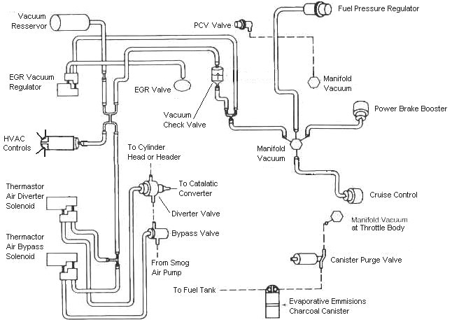
Vacuum diagram 89-93 Mustangs -the 86 should be similar...
Dump codes sticky
Look at the top of the 5.0 Tech forum where the sticky threads are posted. One of them is how to dump the computer codes. Codes may be present even if the CEL (Check Engine Light) isn’t on. You don’t need a code reader or scanner – all you need is a paper clip, or if your lady friend has a hair pin, that will do the job.
I highly suggest that you read it and follow the instructions to dump the codes.
http://www.stangnet.com/mustang-forums/threads/how-to-pull-codes-from-eec4.889006/
See the following website for some help from Tmoss (diagram designer) & Stang&2Birds (website host) for help on 88-95 wiring; http://www.veryuseful.com/mustang/tech/engine/ Everyone should bookmark this site.
TFI module wiring for 94-95 Mustang GT
http://www.veryuseful.com/mustang/tech/engine/images/Mustang-94-95-IgnitionControlModule.gif
Complete computer, actuator & sensor wiring diagram for 91-93 Mass Air Mustangs
http://www.veryuseful.com/mustang/tech/engine/images/91-93_5.0_EEC_Wiring_Diagram.gif
Complete computer, actuator & sensor wiring diagram for 88-91 Mass Air Mustangs
http://www.veryuseful.com/mustang/tech/engine/images/88-91_5.0_EEC_Wiring_Diagram.gif
Ignition switch wiring
http://www.veryuseful.com/mustang/tech/engine/images/IgnitionSwitchWiring.gif
Fuel, alternator, A/C and ignition wiring
http://www.veryuseful.com/mustang/tech/engine/images/fuel-alt-links-ign-ac.gif
O2 sensor wiring harness
http://www.veryuseful.com/mustang/tech/engine/images/mustangO2Harness.gif
Vacuum diagram 89-93 Mustangs
http://www.veryuseful.com/mustang/tech/engine/images/mustangFoxFordVacuumDiagram.jpg
HVAC vacuum diagram
http://www.veryuseful.com/mustang/tech/engine/images/Mustang_AC_heat_vacuum_controls.gif
TFI module differences & pin out
http://www.veryuseful.com/mustang/tech/engine/images/TFI_5.0_comparison.gif
Fuse box layout
http://www.veryuseful.com/mustang/tech/engine/images/MustangFuseBox.gif
Mustang 5.0 Lights and Radio schematic, by TMoss:
http://www.veryuseful.com/mustang/tech/engine/images/mustangFoxLights-Radio_diag.gif
87-92 power window wiring
http://www.veryuseful.com/mustang/tech/engine/images/mustang87-92 PowerWindowWiring.gif
93 power window wiring
http://www.veryuseful.com/mustang/tech/engine/images/mustang93PowerWindows.gif
T5 Cutaway showing T5 internal parts
http://www.veryuseful.com/mustang/tech/engine/images/5_Speed_Cutaway_Illustrated.jpg
Visual comparison of the Ford Fuel Injectors, picture by TMoss:
http://www.veryuseful.com/mustang/tech/engine/images/Ford_Injector_Guide.jpg
Convertible top motor wiring
http://www.veryuseful.com/mustang/tech/engine/images/mustang88VertTopMotorCkt.gif
Engine mounted fuel injector harness
http://www.veryuseful.com/mustang/tech/engine/images/mustangEngineHarness.gif
Location of the TPS, IAB, and the 10-pin connectors on a 5.0, picture by TMoss:
http://www.veryuseful.com/mustang/tech/engine/images/TPS_IAB_Pic.jpg
Starter circuit
http://forums.stangnet.com/attachment.php?attachmentid=21328&d=1080916057
Alternator diagram for 94-95 Mustangs.
http://www.veryuseful.com/mustang/tech/engine/images/Mustang-94-95-Alt.gif