88 mustang GT conv

billl

New Member
Nov 24, 2018
29
0
1
las vegas
Got in the car today and dam it was hard to start when it finally did it backfires out of throttle and tailpipe hard to keep running finally got to idle but it drops off basically acts like it has the old banana in the tailpipe {no banana} tried to drive kept dyeing in the lot replaced Idle control valve no help figures need to go get a smog check for registration


[
 
  • Sponsors (?)


Got in the car today and dam it was hard to start when it finally did it backfires out of throttle and tailpipe hard to keep running finally got to idle but it drops off basically acts like it has the old banana in the tailpipe {no banana} tried to drive kept dyeing in the lot replaced Idle control valve no help figures need to go get a smog check for registration
[

Dump codes sticky

Look at the top of the 5.0 Tech forum where the sticky threads are posted. One of them is how to dump the computer codes. Codes may be present even if the CEL (Check Engine Light) isn’t on. You don’t need a code reader or scanner – all you need is a paper clip, or if your lady friend has a hair pin, that will do the job.
I highly suggest that you read it and follow the instructions to dump the codes. http://www.stangnet.com/mustang-forums/threads/how-to-pull-codes-from-eec4.889006/
 
need to change batt. on my old sunpro code tester and found worn hose from manifold to vacuum resv.{ charcoal box} ? NEXT replace hose try code tester or paper clip.
 
Last edited:
Well, bill, if it were me I would get a repair manual so if/when I want to work on it I have some pictures and words to help me out. For some common problems like yours we have the 'cranks but no start checklist', you can find it in the 5.0 tech/how to threads, jrichker was generous enough to put his wisdom to words for us less mechanically inclined. Read through it so you understand each step, do each step one by one and if you have any questions the members here can help you out.
 
Dump codes sticky

Look at the top of the 5.0 Tech forum where the sticky threads are posted. One of them is how to dump the computer codes. Codes may be present even if the CEL (Check Engine Light) isn’t on. You don’t need a code reader or scanner – all you need is a paper clip, or if your lady friend has a hair pin, that will do the job.
I highly suggest that you read it and follow the instructions to dump the codes. http://www.stangnet.com/mustang-forums/threads/how-to-pull-codes-from-eec4.889006/
checked codes have a 41 oxy sensor
 
checked codes have a 41 oxy sensor
Code 41 or 91. Or 43 Three digit code 172 or 176 - O2 sensor indicates system lean. Look for a vacuum leak or failing O2 sensor.

Revised 24 Aug 2018
1.) To correct the RH & LH mismatch on 91-93 5.0 Mustangs
2.) To add Tmoss’ wiring diagrams for 88-95 Mustangs


Code 41 is the passenger side sensor, as viewed from the driver's seat.
Code 91 is the driver side sensor, as viewed from the driver's seat.

Code 172 is the passenger side sensor as viewed from the driver's seat.
Code 176 is the driver side sensor, as viewed from the driver's seat.

Code 43 is not side specific according to the Probst Ford Fuel injection book.

The computer sees a lean mixture signal coming from the O2 sensors and tries to compensate by adding more fuel. Many times the end result is an engine that runs pig rich and stinks of unburned fuel.

The following is a Quote from Charles O. Probst, Ford fuel Injection & Electronic Engine control:

"When the mixture is lean, the exhaust gas has oxygen, about the same amount as the ambient air. So the sensor will generate less than 400 Millivolts. Remember lean = less voltage.
When the mixture is rich, there's less oxygen in the exhaust than in the ambient air , so voltage is generated between the two sides of the tip. The voltage is greater than 600 millivolts. Remember rich = more voltage.
Here's a tip: the newer the sensor, the more the voltage changes, swinging from as low as 0.1 volt to as much as 0.9 volt. As an oxygen sensor ages, the voltage changes get smaller and slower - the voltage change lags behind the change in exhaust gas oxygen.

Because the oxygen sensor generates its own voltage, never apply voltage and never measure resistance of the sensor circuit. To measure voltage signals, use an analog voltmeter with a high input impedance, at least 10 megohms. Remember, a digital voltmeter will average a changing voltage." End Quote

Testing the O2 sensors 87-93 5.0 Mustangs

Measuring the O2 sensor voltage at the computer will give you a good idea of how well they are working. You'll have to pull the passenger side kick panel off to gain access to the computer connector. Remove the plastic wiring cover to get to the back side of the wiring. Use a safety pin or paper clip to probe the connections from the rear.


Disconnect the O2 sensor from the harness and use the body side O2 sensor harness as the starting point for testing. Do not measure the resistance of the O2 sensor, you may damage it. Resistance measurements for the O2 sensor harness are made with one meter lead on the O2 sensor harness and the other meter lead on the computer wire or pin for the O2 sensor.
Computer wiring harness connector, computer side.
88243.gif


Backside view of the computer wiring connector:
a9x-series-computer-connector-wire-side-view-gif.gif


87-90 5.0 Mustangs:
Computer pin 43 Dark blue/Lt green – LH O2 sensor
Computer pin 29 Dark Green/Pink – RH O2 sensor

The computer pins are 29 (RH O2 with a dark green/pink wire) and 43 (LH O2 with a dark blue/lt green wire). Use the ground next to the computer to ground the voltmeter. The O2 sensor voltage should switch between .2-.9 volt at idle.


91-93 5.0 Mustangs:
Computer pin 43 Red/Black – LH O2 sensor
Computer pin 29 Gray/Lt blue – RH O2 sensor

The computer pins are 29 (RH O2 with a Gray/Lt blue wire) and 43 (LH O2 with a Red/Black wire). Use the ground next to the computer to ground the voltmeter. The O2 sensor voltage should switch between .2-.9 volt at idle.


94-95 5.0 Mustangs; note that the 94-95 uses a 4 wire O2 sensor.
The computer pins are 29 (LH O2 with a red/black wire) and 27 (RH O2 with a gray/lt blue wire). Use pin 32 (gray/red wire) to ground the voltmeter. . The O2 sensor voltage should switch between .2-.9 volt at idle.


Note that all resistance tests must be done with power off. Measuring resistance with a circuit powered on will give false readings and possibly damage the meter. Do not attempt to measure the resistance of the O2 sensors, it may damage them.

Testing the O2 sensor wiring harness
Most of the common multimeters have a resistance scale. Be sure the O2 sensors are disconnected and measure the resistance from the O2 sensor body harness to the pins on the computer. Using the Low Ohms range (usually 200 Ohms) you should see less than 1.5 Ohms.


87-90 5.0 Mustangs:
Computer pin 43 Dark blue/Lt green – LH O2 sensor
Computer pin 29 Dark Green/Pink – RH O2 sensor
Disconnect the connector from the O2 sensor and measure the resistance:
From the Dark blue/Lt green wire in the LH O2 sensor harness and the Dark blue/Lt green wire on the computer pin 43
From the Dark Green/Pink wire on the RH O2 sensor harness and the Dark Green/Pink wire on the computer pin 29


91-93 5.0 Mustangs:
Computer pin 43 Red/Black – LH O2 sensor
Computer pin 29 Gray/Lt blue – RH O2 sensor
Disconnect the connector from the O2 sensor and measure the resistance:
From the Red/Black wire in the LH O2 sensor harness and the Red/Black wire on the computer pin 43
From the Gray/Lt blue wire on the RH O2 sensor harness and the Gray/Lt blue wire on the computer pin 29

94-95 5.0 Mustangs:
Computer pin 29 Red/Black – LH O2 sensor
Computer pin 27 Gray/Lt blue – RH O2 sensor
From the Red/Black wire in the LH O2 sensor harness and the Red/Black wire on the computer pin 29
From the Dark Green/Pink Gray/Lt blue wire on the RH O2 sensor harness and the Gray/Lt blue wire on the computer pin 27


There is a connector between the body harness and the O2 sensor harness. Make sure the connectors are mated together, the contacts and wiring are not damaged, and the contacts are clean and not coated with oil.

The O2 sensor ground (orange wire with a ring terminal on it) is in the wiring harness for the fuel injection wiring. I grounded mine to one of the intake manifold bolts

Check the fuel pressure – the fuel pressure is 37-41 PSI with the vacuum disconnected and the engine idling. Fuel pressure out of range can cause the 41 & 91 codes together. It will not cause a single code, only both codes together.

Make sure you have the proper 3 wire O2 sensors. Only the 4 cylinder cars used a 4 wire sensor, which is not compatible with the V8 wiring harness. The exception is that the 94-95 uses a 4 wire O2 sensor.

Replace the O2 sensors in pairs if replacement is indicated. If one is weak or bad, the other one probably isn't far behind.

Code 41 can also be due to carbon plugging the driver’s side Thermactor air crossover tube on the back of the engine. The tube fills up with carbon and does not pass air to the driver’s side head ports. This puts an excess amount of air in the passenger side exhaust and can set the code 41. Remove the tube and clean it out so that both sides get good airflow: this may be more difficult than it sounds. You need something like a mini rotor-rooter to do the job because of the curves in the tube. Something like the outer spiral jacket of a flexible push-pull cable may be the thing that does the trick.

If you get only code 41 and have changed the sensor, look for vacuum leaks. This is especially true if you are having idle problems. The small plastic tubing is very brittle after many years of the heating it receives. Replace the tubing and check the PVC and the hoses connected to it.

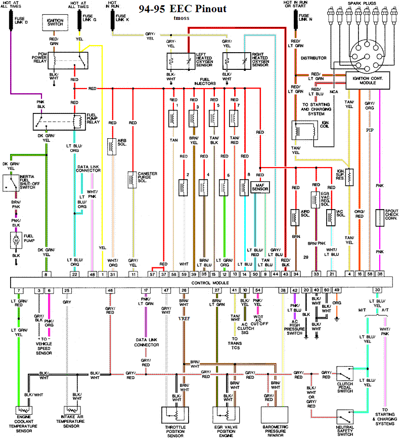
Complete computer, actuator & sensor wiring diagram for 94-95 Mustangs
94-95_5.0_EEC_Wiring_Diagram.gif


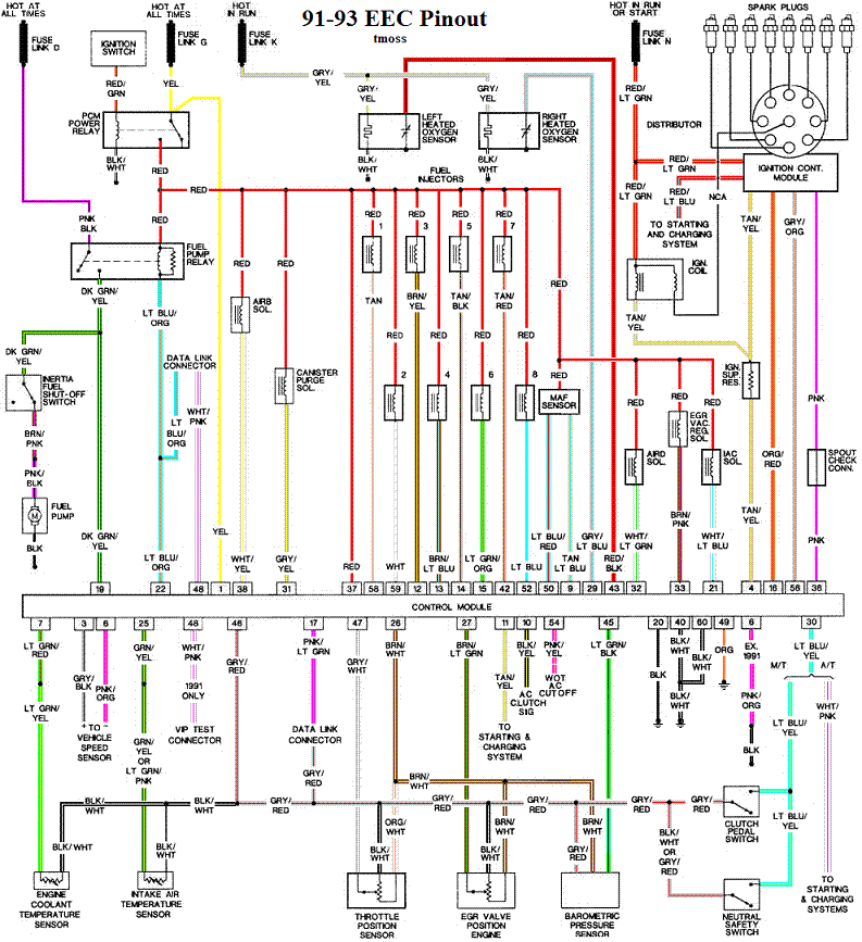
Complete computer, actuator & sensor wiring diagram for 91-93 Mass Air Mustangs
91-93_5.0_EEC_Wiring_Diagram.gif


Complete computer, actuator & sensor wiring diagram for 88-90 Mass Air Mustangs
88-91_5.0_EEC_Wiring_Diagram.gif
 
Thermactor Air System
Some review of how it works...

Revised 26-Jun-2105 to clarify operation of TAB & TAD solenoids

The Thermactor air pump (smog pump) supplies air to the heads or catalytic converters. This air helps break down the excess HC (hydrocarbons) and CO (carbon monoxide). The air supplied to the catalytic converters helps create the catalytic reaction that changes the HC & CO into CO2 and water vapor. Catalytic converters on 5.0 Mustangs are designed to use the extra air provided by the smog pump. Without the extra air, the catalytic converters will clog and fail.

The Thermactor air pump draws air from an inlet filter in the front of the pump. The smog pump puts air into the heads when the engine is cold and then into the catalytic converters when it is warm. The air provided by the air pump serves to help consume any unburned hydrocarbons by supplying extra oxygen to the catalytic process. With a warm engine, the computer operates on closed loop mode, taking input from all the sensors.

The Thermactor control valves serve to direct the flow. The first valve, TAB (Thermactor Air Bypass) or AM1 valve) either dumps air to the atmosphere or passes it on to the second valve. The computer tells the Thermactor Air System to open the Bypass valve at WOT (wide open throttle) minimizing engine drag. This dumps the pump's output to the atmosphere, and reduces the parasitic drag caused by the smog pump to about 2-4 HP at WOT. The Bypass valve also opens during deceleration to reduce or prevent backfires.

The second valve, TAD (Thermactor Air Diverter valve or AM2 valve) directs it to the heads or the catalytic converters. Check valves located after the TAD solenoid prevent hot exhaust gases from damaging the Diverter control valve or air pump in case of a backfire.

Code 44 RH side air not functioning.
Code 94 LH side air not functioning.

How the O2 sensors affect the operation of the Thermactor Air System.
The computer uses the change in the O2 sensor readings to detect operation of the Thermactor control valves. When the dump valve opens, it reduces the O2 readings in the exhaust system. Then it closes the dump valve and the O2 readings increase. By toggling the dump valve (TAB), the computer tests for the 44/94 codes.

Failure mode is usually due to a clogged air crossover tube, where one or both sides of the tube clog with carbon. The air crossover tube mounts on the back of the cylinder heads and supplies air to each of the Thermactor air passages cast into the cylinder heads. When the heads do not get the proper air delivery, they set codes 44 & 94, depending on which passage is clogged. It is possible to get both 44 & 94, which would suggest that the air pump or control valves are not working correctly, or the crossover tube is full of carbon or missing.


thermactor-air-system-65-gif.gif


Computer operation & control for the Thermactor Air System.
Automobile computers use current sink technology. They do not source power to any relay, solenoid or actuator like the IAC, fuel pump relay, or fuel injectors. Instead the computer provides a ground path for the positive battery voltage to get back to the battery negative terminal. That flow of power from positive to negative is what provides the energy to make the IAC, fuel pump relay, or fuel injectors work. No ground provided by the computer, then the actuators and relays don't operate.

One side of the any relay/actuator/solenoid in the engine compartment will be connected to a red wire that has 12-14 volts anytime the ignition switch is in the run position. The other side will have 12-14 volts when the relay/actuator/solenoid isn't turned on. Once the computer turns on the clamp side, the voltage on the computer side of the wire will drop down to 1 volt or less.

In order to test the TAD/TAB solenoids, you need to ground the white/red wire on the TAB solenoid or the light green/black wire on the TAD solenoid. The TAB and TAD solenoid are located on the passenger side shock strut tower. Uneducated owners sometimes remove them to get more HP. This does not work, it just causes 81 & 82 codes.

For 94-95 cars: the colors are different. The White/Red wire (TAB control) is White/Orange (Pin 31 on the PCM). The Green/Black wire (TAD control) should be Brown (pin 34 at the PCM). Thanks to HISSIN50 for this tip.

Testing the system:

To test the computer, you can use a test light across the TAB or TAD wiring connectors and dump the codes. When you dump the codes, the computer does a self test that toggles every relay/actuator/solenoid on and off. When this happens, the test light will flicker.

Disconnect the big hose from smog pump: with the engine running you should feel air output. Reconnect the smog pump hose & apply vacuum to the first vacuum controlled valve: Its purpose is to either dump the pump's output to the atmosphere or pass it to the next valve.

The next vacuum controlled valve directs the air to either the cylinder heads when the engine is cold or to the catalytic converter when the engine is warm. Disconnect the big hoses from the back side of the vacuum controlled valve and start the engine. Apply vacuum to the valve and see if the airflow changes from one hose to the next.

The two electrical controlled solenoid vacuum valves mounted on the rear of the passenger side wheel well turn the vacuum on & off under computer control. Check to see that both valves have +12 volts on the red wire. Then ground the white/red wire and the first solenoid should open and pass vacuum. Do the same thing to the light green/black wire on the second solenoid and it should open and pass vacuum.

Remember that the computer does not source power for any actuator or relay, but provides the ground necessary to complete the circuit. That means one side of the circuit will always be hot, and the other side will go to ground or below 1 volt as the computer switches on that circuit.

The computer provides the ground to complete the circuit to power the solenoid valve that turns the
vacuum on or off. The computer is located under the passenger side kick panel. Remove the kick panel & the cover over the computer wiring connector pins. Check Pin 38 Solenoid valve #1 that provides vacuum to the first Thermactor control valve for a switch from 12-14 volts to 1 volt or less. Do the same with pin 32 solenoid valve #2 that provides vacuum to the second Thermactor control valve. Starting the engine with the computer jumpered to self test mode will cause all the actuators to toggle on and off. If after doing this and you see no switching of the voltage on and off, you can start testing the wiring for shorts to ground and broken wiring. An Ohm check to ground with the computer connector disconnected & the solenoid valves disconnected should show open circuit between the pin 32 and ground and again on pin 38 and ground. In like manner, there should be less than 1 ohm between pin 32 and solenoid valve #2 and pin 38 & Solenoid valve #1.

If after checking the resistance of the wiring & you are sure that there are no wiring faults, start looking at the solenoid valves. If you disconnect them, you can jumper power & ground to them to verify operation. Power & ground supplied should turn on the vacuum flow, remove either one and the vacuum should stop flowing.

Typical resistance of the solenoid valves is in the range of 20-70 Ohms.

Code 45 & 46 are very uncommon, this is the first time in 20+ years here at Stangnet that I have seen them posted.

The TAD solenoid and diverter valve and its plumbing are the probable source since it appears that the TAD solenoid is stuck open during self-test. Check for vacuum at the Diverter valve when running the self-test routine.


Thermactor Air System theory of operation:
Catalytic converters consist of two different types of catalysts: Reduction and Oxidation.
The Reduction catalyst is the first converter in a 5.0 Mustang, and the Oxidation converter is the second converter. The Oxidation converter uses the extra air from the smog pump to burn the excess HC. Aftermarket converters that use the smog pump often combine both types of catalysts in one housing. Since all catalytic reactions depend on heat to happen, catalytic converters do not work as efficiently with long tube headers. The extra length of the long tubes reduces the heat available to operate the O2 sensors and the catalytic converters. That will cause emissions problems, and reduce the chances of passing an actual smog test.


Now for the Chemistry...
"The reduction catalyst is the first stage of the catalytic converter. It uses platinum and rhodium to help reduce the NOx emissions. When an NO or NO2 molecule contacts the catalyst, the catalyst rips the nitrogen atom out of the molecule and holds on to it, freeing the oxygen in the form of O2. The nitrogen atoms bond with other nitrogen atoms that are also stuck to the catalyst, forming N2. For example:

2NO => N2 + O2 or 2NO2 => N2 + 2O2

The oxidation catalyst is the second stage of the catalytic converter. It reduces the unburned hydrocarbons and carbon monoxide by burning (oxidizing) them over a platinum and palladium catalyst. This catalyst aids the reaction of the CO and hydrocarbons with the remaining oxygen in the exhaust gas. For example:

2CO + O2 => 2CO2

There are two main types of structures used in catalytic converters -- honeycomb and ceramic beads. Most cars today use a honeycomb structure." Quote courtesy of How Stuff Works (HowStuffWorks "Catalysts")

What happens when there is no extra air from the smog pump...
As engines age, the quality of tune decreases and wear causes them to burn oil. We have all seem cars that go down the road puffing blue or black smoke from the tailpipe. Oil consumption and poor tune increase the amount of HC the oxidation catalyst has to deal with. The excess HC that the converters cannot oxidize due to lack of extra air becomes a crusty coating inside the honeycomb structure. This effectively reduces the size of the honeycomb passageways and builds up thicker over time and mileage. Continuous usage under such conditions will cause the converter to fail and clog. The extra air provided by the Thermactor Air System (smog pump) is essential for the oxidation process. It oxidizes the added HC from oil consumption and poor tune and keeps the HC levels within acceptable limits.

Newer catalytic converters do not use the Thermactor Air System (smog pump) because they are designed to work with an improved computer system that runs leaner and cleaner
They add an extra set of O2 sensors after the catalytic converters to monitor the oxygen and HC levels. Using this additional information, the improved computer system monitors the health and efficiency of the catalytic converters. If the computer cannot compensate for the added load of emissions due to wear and poor tune, the catalytic converters will eventually fail and clog. The periodic checks (smog inspections) are supposed to help owners keep track of problems and get them repaired. Use them on an 86-95 Mustang and you will slowly kill them with the pollutants that they are not designed to deal with.
 
I've found the SD cars tend to backfire and run crappy when there is a vac leak. They are very sensitive to manifold pressure and you won't see a code thrown for it.

If you have a smoke machine...use it.
 
I've found the SD cars tend to backfire and run crappy when there is a vac leak. They are very sensitive to manifold pressure and you won't see a code thrown for it.

If you have a smoke machine...use it.
Thanks this should keep me busy thru winter. It just happened 1 morning out of nowhere now its undrivable absolutely will not take a load theres no visable hose leaks but will keep looking
 
Thermactor Air System
Some review of how it works...

Revised 26-Jun-2105 to clarify operation of TAB & TAD solenoids

The Thermactor air pump (smog pump) supplies air to the heads or catalytic converters. This air helps break down the excess HC (hydrocarbons) and CO (carbon monoxide). The air supplied to the catalytic converters helps create the catalytic reaction that changes the HC & CO into CO2 and water vapor. Catalytic converters on 5.0 Mustangs are designed to use the extra air provided by the smog pump. Without the extra air, the catalytic converters will clog and fail.

The Thermactor air pump draws air from an inlet filter in the front of the pump. The smog pump puts air into the heads when the engine is cold and then into the catalytic converters when it is warm. The air provided by the air pump serves to help consume any unburned hydrocarbons by supplying extra oxygen to the catalytic process. With a warm engine, the computer operates on closed loop mode, taking input from all the sensors.

The Thermactor control valves serve to direct the flow. The first valve, TAB (Thermactor Air Bypass) or AM1 valve) either dumps air to the atmosphere or passes it on to the second valve. The computer tells the Thermactor Air System to open the Bypass valve at WOT (wide open throttle) minimizing engine drag. This dumps the pump's output to the atmosphere, and reduces the parasitic drag caused by the smog pump to about 2-4 HP at WOT. The Bypass valve also opens during deceleration to reduce or prevent backfires.

The second valve, TAD (Thermactor Air Diverter valve or AM2 valve) directs it to the heads or the catalytic converters. Check valves located after the TAD solenoid prevent hot exhaust gases from damaging the Diverter control valve or air pump in case of a backfire.

Code 44 RH side air not functioning.
Code 94 LH side air not functioning.

How the O2 sensors affect the operation of the Thermactor Air System.
The computer uses the change in the O2 sensor readings to detect operation of the Thermactor control valves. When the dump valve opens, it reduces the O2 readings in the exhaust system. Then it closes the dump valve and the O2 readings increase. By toggling the dump valve (TAB), the computer tests for the 44/94 codes.

Failure mode is usually due to a clogged air crossover tube, where one or both sides of the tube clog with carbon. The air crossover tube mounts on the back of the cylinder heads and supplies air to each of the Thermactor air passages cast into the cylinder heads. When the heads do not get the proper air delivery, they set codes 44 & 94, depending on which passage is clogged. It is possible to get both 44 & 94, which would suggest that the air pump or control valves are not working correctly, or the crossover tube is full of carbon or missing.


thermactor-air-system-65-gif.gif


Computer operation & control for the Thermactor Air System.
Automobile computers use current sink technology. They do not source power to any relay, solenoid or actuator like the IAC, fuel pump relay, or fuel injectors. Instead the computer provides a ground path for the positive battery voltage to get back to the battery negative terminal. That flow of power from positive to negative is what provides the energy to make the IAC, fuel pump relay, or fuel injectors work. No ground provided by the computer, then the actuators and relays don't operate.

One side of the any relay/actuator/solenoid in the engine compartment will be connected to a red wire that has 12-14 volts anytime the ignition switch is in the run position. The other side will have 12-14 volts when the relay/actuator/solenoid isn't turned on. Once the computer turns on the clamp side, the voltage on the computer side of the wire will drop down to 1 volt or less.

In order to test the TAD/TAB solenoids, you need to ground the white/red wire on the TAB solenoid or the light green/black wire on the TAD solenoid. The TAB and TAD solenoid are located on the passenger side shock strut tower. Uneducated owners sometimes remove them to get more HP. This does not work, it just causes 81 & 82 codes.

For 94-95 cars: the colors are different. The White/Red wire (TAB control) is White/Orange (Pin 31 on the PCM). The Green/Black wire (TAD control) should be Brown (pin 34 at the PCM). Thanks to HISSIN50 for this tip.

Testing the system:

To test the computer, you can use a test light across the TAB or TAD wiring connectors and dump the codes. When you dump the codes, the computer does a self test that toggles every relay/actuator/solenoid on and off. When this happens, the test light will flicker.

Disconnect the big hose from smog pump: with the engine running you should feel air output. Reconnect the smog pump hose & apply vacuum to the first vacuum controlled valve: Its purpose is to either dump the pump's output to the atmosphere or pass it to the next valve.

The next vacuum controlled valve directs the air to either the cylinder heads when the engine is cold or to the catalytic converter when the engine is warm. Disconnect the big hoses from the back side of the vacuum controlled valve and start the engine. Apply vacuum to the valve and see if the airflow changes from one hose to the next.

The two electrical controlled solenoid vacuum valves mounted on the rear of the passenger side wheel well turn the vacuum on & off under computer control. Check to see that both valves have +12 volts on the red wire. Then ground the white/red wire and the first solenoid should open and pass vacuum. Do the same thing to the light green/black wire on the second solenoid and it should open and pass vacuum.

Remember that the computer does not source power for any actuator or relay, but provides the ground necessary to complete the circuit. That means one side of the circuit will always be hot, and the other side will go to ground or below 1 volt as the computer switches on that circuit.

The computer provides the ground to complete the circuit to power the solenoid valve that turns the
vacuum on or off. The computer is located under the passenger side kick panel. Remove the kick panel & the cover over the computer wiring connector pins. Check Pin 38 Solenoid valve #1 that provides vacuum to the first Thermactor control valve for a switch from 12-14 volts to 1 volt or less. Do the same with pin 32 solenoid valve #2 that provides vacuum to the second Thermactor control valve. Starting the engine with the computer jumpered to self test mode will cause all the actuators to toggle on and off. If after doing this and you see no switching of the voltage on and off, you can start testing the wiring for shorts to ground and broken wiring. An Ohm check to ground with the computer connector disconnected & the solenoid valves disconnected should show open circuit between the pin 32 and ground and again on pin 38 and ground. In like manner, there should be less than 1 ohm between pin 32 and solenoid valve #2 and pin 38 & Solenoid valve #1.

If after checking the resistance of the wiring & you are sure that there are no wiring faults, start looking at the solenoid valves. If you disconnect them, you can jumper power & ground to them to verify operation. Power & ground supplied should turn on the vacuum flow, remove either one and the vacuum should stop flowing.

Typical resistance of the solenoid valves is in the range of 20-70 Ohms.

Code 45 & 46 are very uncommon, this is the first time in 20+ years here at Stangnet that I have seen them posted.

The TAD solenoid and diverter valve and its plumbing are the probable source since it appears that the TAD solenoid is stuck open during self-test. Check for vacuum at the Diverter valve when running the self-test routine.


Thermactor Air System theory of operation:
Catalytic converters consist of two different types of catalysts: Reduction and Oxidation.

The Reduction catalyst is the first converter in a 5.0 Mustang, and the Oxidation converter is the second converter. The Oxidation converter uses the extra air from the smog pump to burn the excess HC. Aftermarket converters that use the smog pump often combine both types of catalysts in one housing. Since all catalytic reactions depend on heat to happen, catalytic converters do not work as efficiently with long tube headers. The extra length of the long tubes reduces the heat available to operate the O2 sensors and the catalytic converters. That will cause emissions problems, and reduce the chances of passing an actual smog test.


Now for the Chemistry...
"The reduction catalyst is the first stage of the catalytic converter. It uses platinum and rhodium to help reduce the NOx emissions. When an NO or NO2 molecule contacts the catalyst, the catalyst rips the nitrogen atom out of the molecule and holds on to it, freeing the oxygen in the form of O2. The nitrogen atoms bond with other nitrogen atoms that are also stuck to the catalyst, forming N2. For example:

2NO => N2 + O2 or 2NO2 => N2 + 2O2

The oxidation catalyst is the second stage of the catalytic converter. It reduces the unburned hydrocarbons and carbon monoxide by burning (oxidizing) them over a platinum and palladium catalyst. This catalyst aids the reaction of the CO and hydrocarbons with the remaining oxygen in the exhaust gas. For example:

2CO + O2 => 2CO2

There are two main types of structures used in catalytic converters -- honeycomb and ceramic beads. Most cars today use a honeycomb structure." Quote courtesy of How Stuff Works (HowStuffWorks "Catalysts")

What happens when there is no extra air from the smog pump...
As engines age, the quality of tune decreases and wear causes them to burn oil. We have all seem cars that go down the road puffing blue or black smoke from the tailpipe. Oil consumption and poor tune increase the amount of HC the oxidation catalyst has to deal with. The excess HC that the converters cannot oxidize due to lack of extra air becomes a crusty coating inside the honeycomb structure. This effectively reduces the size of the honeycomb passageways and builds up thicker over time and mileage. Continuous usage under such conditions will cause the converter to fail and clog. The extra air provided by the Thermactor Air System (smog pump) is essential for the oxidation process. It oxidizes the added HC from oil consumption and poor tune and keeps the HC levels within acceptable limits.

Newer catalytic converters do not use the Thermactor Air System (smog pump) because they are designed to work with an improved computer system that runs leaner and cleaner
They add an extra set of O2 sensors after the catalytic converters to monitor the oxygen and HC levels. Using this additional information, the improved computer system monitors the health and efficiency of the catalytic converters. If the computer cannot compensate for the added load of emissions due to wear and poor tune, the catalytic converters will eventually fail and clog. The periodic checks (smog inspections) are supposed to help owners keep track of problems and get them repaired. Use them on an 86-95 Mustang and you will slowly kill them with the pollutants that they are not designed to deal with.
THANKS I really appreciate your posts looks like I have a lot to do.
 
Look at all the hard vacuum lines, When they break, it's not very visible because it's hidden inside the rubber end fittings.
Could also be the fuel pump, it's probably be 30 years old.
Fuel pump was my first thought replaced it 3x last time not so long ago changed fuel filter and added 6gl gas incase it was running on crude in bottom of tank. I'm going to have to add check fuel pressure to growing list whats the best way on a 88 mustang GT conv. 5.0 ? All the other times the car would run fine then just die. After it cooled down 20 min would run 1/4 mile then stop....repeat...
 
Schrader valve on the fuel rail. Jus to need to connect a guage to it.

Should be 39psi vacuum off the regulator and capped. With vacuum on, pressure should be around 33-36psi and shoot to 39 if you blip the throttle