
I have a maf car it has gt40p heads and tfs intake. It has the smog pump delete and I’ve check for vacuum leaks and the iac. TPS is set right and timing is good. Cap, rotor, plugs, and plugs are good. Any ideas would be awesome.

I have a maf car it has gt40p heads and tfs intake. It has the smog pump delete and I’ve check for vacuum leaks and the iac. TPS is set right and timing is good. Cap, rotor, plugs, and plugs are good. Any ideas would be awesome.

Thank you so much I’ve been watching YouTube for days now and haven’t found anythingStep 1
Dump codes sticky
Look at the top of the 5.0 Tech forum where the sticky threads are posted. One of them is how to dump the computer codes. Codes may be present even if the CEL (Check Engine Light) isn’t on. You don’t need a code reader or scanner – all you need is a paper clip, or if your lady friend has a hair pin, that will do the job.
http://www.stangnet.com/mustang-forums/threads/how-to-pull-codes-from-eec4.889006/
If that does not work, here's Step 2...
Computer will not go into diagnostic mode on 86-90 models 5.0 Mustangs .
Revised 23 May 2020 to include warning about jumpering the dark brown connector with a black/orange wire.(12 volts) to the test connector.
Disconnect the battery positive terminal before making any resistance checks.
The voltage drop in the ground cable will cause incorrect resistance readings.
How it is supposed to work:
The black/white wire (pin 46) is signal ground for the computer. It provides a dedicated ground for the EGR, Baro, ACT, ECT, & TPS sensors as well as the ground to put the computer into self test mode. If this ground is bad, none of the sensors mentioned will work properly. That will severely affect the car's performance. You will have hard starting, low power and drivability problems. Since it is a dedicated ground, it passes through the computer on its way to the computer main power ground that terminates at the battery pigtail ground. It should read less than 1.5 ohms when measured from any signal ground on the engine mounted fuel injector harness with the battery pigtail ground as the other reference point for the ohmmeter probe.
Engine mounted fuel injector wiring harness sensors for a 5.0 mustang
What sometimes happens is that the test connector black/white wire gets jumpered to power which either burns up the wiring or burns the trace off the pc board inside the computer. That trace connects pins 46 to pins 40 & 60.
WARNING!!! There is a single dark brown connector with a black/orange wire. It is the 12 volt power to the under the hood light. Do not jumper it to the computer test connector. If you do, you will damage the computer.
OR
If an O2 sensor harness from an automatic transmission Mustang is used with an A9L manual shift transmission computer. The 12 volts from the automatic transmission starter circuit will damage the A9L computer.
The STI (Self Test Input) is jumpered to ground to put the computer into test mode. Jumpering it to power can produce unknown results, including damage to the computer. The ohm test simply verifies that there are no breaks in the wiring between the test connector and the computer input.
How to test the wiring:
With the power off, measure the resistance between the computer test ground (black/white wire) on the self test connector and battery ground. You should see less than 1.5 ohms.
If that check fails, remove the passenger side kick panel and disconnect the computer connector. There is a 10 MM bolt that holds it in place. Measure the resistance between the black/white wire and pin 46 on the computer wiring connector: it should be less than 1.5 ohms. More than 1.5 ohms is a wiring problem. If it reads 1.5 ohms or less, then the computer is suspect. On the computer, measure the resistance between pin 46 and pins 40 & 60: it should be less than 1.5 ohms. More than that and the computer’s internal ground has failed, and the computer needs to be repaired or replaced.
While you have the computer connector disconnected from the computer, turn the ignition switch to the Start position and look for 12 volts on pin 46 of the computer wiring harness. If you see 12 volts then you have an automatic transmission O2 sensor harness. That will damage the A9L manual shift transmission computer.
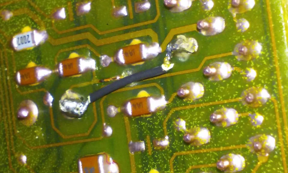
See the pictures below for help finding and fixing the burnt computer trace.
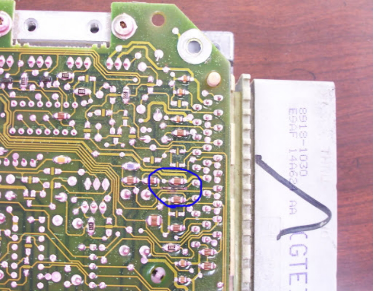
The fix is some careful soldering of a small jumper wire across the burnt section of copper trace.
If the first ground check was good, there are other wires to check. Measure the resistance between the STI computer self test connector (red/white wire) and pin 48 on the computer main connector: it should be less than 1.5 ohms. More than 1.5 ohms is a wiring problem
The following is a view from the computer side of the computer wiring connector: it is for an A9L, A9P computer.

Diagram courtesy of Tmoss & Stang&2birds
Check out the diagram and notice all the places the black/white wire goes. Almost every sensor on the engine except the MAF is connected to it.
See the following website for some help from Tmoss (diagram designer) & Stang&2Birds
(website host) for help on 88-95 wiring http://www.veryuseful.com/mustang/tech/engine
See the graphic for the 10 pin connector circuit layout.

Then you should really like this:Thank you so much I’ve been watching YouTube for days now and haven’t found anything


