90 Lx Fuel Pump Stays Running When Key On Wont Start When Cold Any Ideas?

Tom Musso 90 lx

New Member
Aug 9, 2013
9
0
2
I have a 90 lx 5.0 that won't start when cold, I have not had a chance to check fuel pressure, but have noticed that fuel pump doesn't shut off when you just have key turned on. From what I have read it should only run for 2-5 seconds then shut off unless you start car. I can hear fuel flowing through fuel rail, but it will not start when engine is cold. I also am not able to run the codes, the check engine light just stays on and does not flash, I even took it to my local parts store and hooked it up to there scanner and got same results ,nothing. I am wondering if computer is bad? It also runs extremely rich when it is running, clouds of black smoke. Any ideas? Thanks in advance for any help.
 
  • Sponsors (?)


Start with the not able to dump codes and fix that first, then chase the other rabbits...

Computer will not go into diagnostic mode on 86-90 model 5.0 Mustangs

Disconnect the battery positive terminal before making any resistance checks.
The voltage drop in the ground cable will cause incorrect resistance readings.


How it is supposed to work:
The black/white wire (pin 46) is signal ground for the computer. It provides a dedicated ground for the EGR, Baro, ACT, ECT, & TPS sensors as well as the ground to put the computer into self test mode. If this ground is bad, none of the sensors mentioned will work properly. That will severely affect the car's performance. You will have hard starting, low power and drivability problems. Since it is a dedicated ground, it passes through the computer on its way to the computer main power ground that terminates at the battery pigtail ground. It should read less than 1.5 ohms when measured from anyplace on the engine harness with the battery pigtail ground as the other reference point for the ohmmeter probe.

What sometimes happens is that the test connector black/white wire gets jumpered to power which either burns up the wiring or burns the trace off the pc board inside the computer. That trace connects pins 46 to pins 40 & 60.

The STI (Self Test Input ) is jumpered to ground to put the computer into test mode. Jumpering it to power can produce unknown results, including damage to the computer. The ohm test simply verifies that there are no breaks in the wiring between the test connector and the computer input.

How to test the wiring :
With the power off, measure the resistance between the computer test ground (black/white wire) on the self test connector and battery ground. You should see less than 1.5 ohms.

attachment.php


If that check fails, remove the passenger side kick panel and disconnect the computer connector. There is a 10 MM bolt that holds it in place. Measure the resistance between the black/white wire and pin 46 on the computer wiring connector: it should be less than 1.5 ohms. More that 1.5 ohms is a wiring problem. If it reads 1.5 ohms or less, then the computer is suspect. On the computer, measure the resistance between pin 46 and pins 40 & 60: it should be less than 1.5 ohms. More that that and the computer’s internal ground has failed, and the computer needs to be repaired or replaced.

See http://www.stangnet.com/mustang-forums/749974-computer-issue.html#post7490537 for Joel5.0’s fix for the computer internal signal ground.

If the first ground check was good, there are other wires to check. Measure the resistance between the STI computer self test connector (red/white wire) and pin 48 on the computer main connector: it should be less than 1.5 ohms. More that 1.5 ohms is a wiring problem

The following is a view from the computer side of the computer wiring connector: it is for an A9L, A9P computer.
eec04.gif


a9x-series-computer-connector-wire-side-view-gif.71316


Diagram courtesy of Tmoss & Stang&2birds

Check out the diagram and notice all the places the black/white wire goes. Almost every sensor on the engine except the MAF is connected to it.

88-91_5.0_EEC_Wiring_Diagram.gif


See the following website for some help from Tmoss (diagram designer) & Stang&2Birds
(website host) for help on 88-95 wiring http://www.veryuseful.com/mustang/tech/engine

See the graphic for the 10 pin connector circuit layout.
salt-pepper-10-pin-connectors-65-jpg.68512
 
I don't know if this is the same issue that you have, and I would check what jrichkter said first.

I had a few leaking or clogged fuel injectors. Once I shut the car off I would lose my fuel pressure in about 5 or 10 minutes. When the car was cold or enough fuel leaked in the engine, it was really hard to start. It would stumble for a few minutes until the extra fuel burned out.

Your issue definitely sounds like its something with the fuel system.
 
The fuel pump doesn't shut off problem is common. It is electrical, not fuel related until proven otherwise. As jrichker said fix the code read problem first then explore the fuel pump problem. More than likely it is the fuel pump relay. follow jrichkers advice and you will fix it in less time and with less money. Shortcuts don't exist so don't bother with them.
 
All symptoms you're saying it sounds like a bad computer. I've dealt with 2 in my personal trucks, but the cars usually don't have the computer issues. Probably because the cars have a much better location. I'd follow JR's advice first because he's the man. But keep in the back of your head that you may need a good used/new computer.

FYI I've heard a lot that auto parts store computers won't have a properly working KAM function in them. Mine doesn't, I always get a code for the Keep Alive Memory (i've checked the wiring so I know it's computer related), and that means every time the car shuts off, it loses everything it just learned in the driving period.
 
Ok I was confused by diagram on the black and white wire on self test plug mine is tan with red stripe, in the position thats in diagram, i noticed that said 86-88. I tested that and came up with .6 ohms should be good right? I will test pins on computer tomorrow night, I did take kick panel off and pulled out the wires to access the plug. Someone has been in there and written ok on two of the plugs or is that from factory? I did notice just below the coil a lead that had two black with white stripe wires, what is that? That also had ok marked on it. I put the meter on that also and came up with 4.4 on ohm meter. These were the only black/ white wire I could find, but they were not anywhere near the self test plug. Thanks for the help ill let you know what I come up with on computer pin test.
 
If the sensors lose their ground, they will not function correctly. That will cause all sorts of problems.

Troubleshooting loss of signal ground

Revised 21-Aug-2013 to rewrite the MAP/Baro testing of the signal ground and moving the testing the computer’s internal signal ground test procedure to the last place.

1.) The computer pin 46 signal ground is a critical component: it provides ground for the
Map/Baro, TPS, ECT, EGR position sensor and ACT. Signal ground is used in many circuits that have analog inputs to isolate the electrical noise. It is always separate from power ground, although both may have a common connection origination point. Signal ground usually has some conditioning that reduces the electrical noise to prevent false readings. The black/white wire (pin 46) is signal ground for the computer. It provides a dedicated ground for the EGR, Baro, ACT, ECT, & TPS sensors as well as the ground to put the computer into self test mode. If this ground is bad, none of the sensors mentioned will work properly. That will severely affect the car's performance. You will have hard starting, low power and drivability problems. What sometimes happens is that the test connector black/white wire gets jumpered to power which either burns up the wiring or burns the trace off the pc board inside the computer. That trace connects pins 46 to pins 40 & 60.

2.) Troubleshooting signal ground problems:

Note that all resistance tests must be done with power off. Measuring resistance with a circuit powered on will give false readings and possibly damage the meter. That means disconnecting the battery positive cable since there is always some current draw due to the computer and radio circuits.[/b]

A.) With the power off, measure the resistance between the computer test ground
(black/white wire) on the self test connector and battery ground. You should see less than 1.5 ohms.
attachment.php


B.) MAP/Baro circuit: check the resistance between the black/white wire on the MAP/Baro sensor and the negative battery cable. It should be less than 1.5 ohms. If it isn’t you can figure that you have serious problems with the wiring for the computer or the computer’s internal signal ground. Check the resistance between the black/white wire on the MAP/Baro sensor and then the black/white wire on the EGR and the same wire on the TPS. Repeat the process with the black/white wire on the ACT & ECT sensors and the MAP/Baro sensor black/white wire It should be less than 1 ohms. Higher resistance than 1 ohms indicates a problem with the 10 pin connector or the splice inside the main harness where the wire from the 10 pin connectors joins the rest of the black/white wire

C.) Engine mounted sensor circuit: Check the resistance between the black/white wire on the TPS and battery ground. It should be less than 1.5 ohms. Higher resistance than 1.5 ohms indicates a problem with the 10 pin connector or the splice inside the main harness where the wire from the 10 pin connectors joins the rest of the black/white wire.

Repeat the process for the ACT and ECT sensors. Your results should have the same specifications.

attachment.php


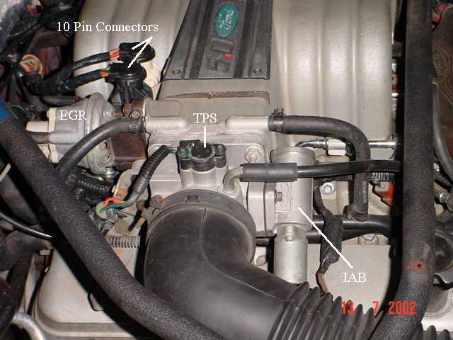
See the graphic for the location of the 10 pin connectors:

Diagram courtesy of Tmoss & Stang&2birds

TPS_IAB_Pic.jpg


See the graphic for the 10 pin connector circuit layout.
salt-pepper-10-pin-connectors-65-jpg.68512

The injector power pin is the VPWR pin in the black 10 pin connector.


3.) Testing the computer's internal signal ground:
Remove the passenger side kick panel and disconnect the computer connector. There is a 10 MM bolt that holds it in place. Measure the resistance between the black/white wire and pin 46 on the computer wiring connector: it should be less than 1.5 ohms. More that 1.5 ohms is a wiring problem. If it reads 1.5 ohms or less, then the computer is suspect. On the computer, measure the resistance between pin 46 and pins 40 & 60: it should be less than 1.5 ohms. More than that and the computer’s internal ground has failed, and the computer needs to be repaired or replaced.

See http://www.stangnet.com/mustang-forums/749974-computer-issue.html#post7490537 for Joel5.0’s fix to the computer internal signal ground.

If the ground for the TPS goes bad, the TPS output voltage increases and the idle speed may fluctuate..
attachment.php