I'm fixing to dump a lot of very technical stuff on your plate, so you may want to print it out and highlight the sections that relate to your current problem.
Dump the codes: Codes may be present even if the Check Engine Light (CEL) isn't on.
Dumping the computer diagnostic codes on 86-95 Mustangs
Revised 26-July-2011. Added need to make sure the clutch is pressed when dumping codes.
Codes may be present even if the check engine light hasn’t come on, so be sure to check for them.
Here's the way to dump the computer codes with only a jumper wire or paper clip and the check engine light, or test light or voltmeter. I’ve used it for years, and it works great. You watch the flashing test lamp or Check Engine Light and count the flashes.
Post the codes you get and I will post 86-93 model 5.0 Mustang specific code definitions and fixes. I do not have a complete listing for 94-95 model 5.0 Mustangs at this time.
Be sure to turn off the A/C, and put the transmission in neutral when dumping the codes. On a manual transmission car, be sure to press the clutch to the floor.
Fail to do this and you will generate a code 67 and not be able to dump the Engine Running codes.
If your car is an 86-88 stang, you'll have to use the test lamp or voltmeter method. There is no functional check engine light on the 86-88's except possibly the Cali Mass Air cars.
The STI has a gray connector shell and a white/red wire. It comes from the same bundle of wires as the self test connector.
89 through 95 cars have a working Check Engine light. Watch it instead of using a test lamp.
The STI has a gray connector shell and a white/red wire. It comes from the same bundle of wires as the self test connector.
WARNING!!! There is a single dark brown connector with a black/orange wire. It is the 12 volt power to the under the hood light. Do not jumper it to the computer test connector. If you do, you will damage the computer.
What to expect:
You should get a code 11 (two single flashes in succession). This says that the computer's internal workings are OK, and that the wiring to put the computer into diagnostic mode is good. No code 11 and you have some wiring problems.
This is crucial: the same wire that provides the ground to dump the codes provides signal ground for the TPS, EGR, ACT and Map/Baro sensors. If it fails, you will have poor performance, economy and driveablity problems
Some codes have different answers if the engine is running from the answers that it has when the engine isn't running. It helps a lot to know if you had the engine running when you ran the test.
Dumping the Engine Running codes: The procedure is the same, you start the engine with the test jumper in place. Be sure the A/C is off, and clutch (if present) is pressed to the floor, and the transmission is in neutral. You'll get an 11, then a 4 and the engine will speed up to do the EGR test. After the engine speed decreases back to idle, it will dump the engine running codes.
Trouble codes are either 2 digit or 3 digit, there are no cars that use both 2 digit codes and 3 digit codes.
Your 86-88 5.0 won't have a working Check Engine Light, so you'll need a test light.
See AutoZone Part Number: 25886 , $10
Alternate methods:
For those who are intimidated by all the wires & connections, see
Actron® for what a typical hand scanner looks like. Normal retail price is about $30 or so at AutoZone or Wal-Mart.
Or for a nicer scanner see
Equus Digital Ford Code Reader (3145) Equus - Digital Ford Code Reader (3145It has a 3 digit LCD display so that you don’t have to count flashes or beeps.. Cost is $22-$36.
Fuel Quantity gauge troubleshooting 87-93 Mustangs
The red/yellow wire (power supply to gauge & sender) should have 12 volts when the ignition is in the start or Run position.
Troubleshooting the gauge and sender circuit:
Since the sender uses a variable resistor, sum the resistor values of 22 Ohms (empty value) & 145 Ohms (full value). That gets you 167, which you divide by 2: that gets you 83.5. So in theory, 83.5 ohms is 1/2 full. A trip to Radio Shack for the closest combination of resistors to make 83.5 ohms gets you one 68 Ohm (Catalog #: 271-1106) + one 15 Ohm (Catalog #: 271-1102) for a total of 83 Ohms at the cost of $2 plus tax. Wire the resistors in series to make a resistor pack and cover it with heat shrink tubing or electrical tape. The 83 Ohms is close enough to the 83.5 Ohm figure that it shouldn't matter. Disconnect the electrical connector shown in your for the tank sender unit. Connect one end of the resistor pack to the yellow/white wire on the body side fuel sender electrical connector and the other end of the resistor pack to ground. Make sure nothing is touching that isn't supposed to and turn the ignition switch to Run. If I am correct, the fuel gauge will read 1/2 full, or very close to it. If it does not, then the odds are that the gauge or anti-slosh unit are bad.
How and why the test works…
Most of the fuel gauge failures give a stuck on full or stuck on empty as a problem symptom. Using a resistor combination that mimics 1/2 tank allows you to decide if the gauge and anti-slosh module are the problem source.
If the gauge reads about 1/2 tank with the resistor combination, that points to the sender as being the culprit.
If the gauge reads full or empty with the resistor pack in place of the sender, then the gauge or anti-slosh module is at fault.
Fuel gauge sender testing and replacement
The next steps require dropping the fuel tank and removal of the fuel level sender. Here are some useful tips...
I have done the tank removal three times, and the main issues are getting the car up on jack stands and getting the gas out of the tank. DO NOT try to do this job without jack stands. Becoming a pancake is not part of the repair process.
Pumping out the old gas:
If the old pump still works, you can use it to pump the tank out.
1.) Separate the pressure line (the one with the Schrader valve on it) using the fuel line tools.
Look in the A/C repair section for the fuel line tools. They look like little plastic top hats. You will need the 1/2" & 5/8" ones. The hat shaped section goes on facing the large part of the coupling. Then you press hard on the brim until it forces the sleeve into the coupling and releases the spring. You may need someone to pull on the line while you press on the coupling.
Use a piece of garden hose to run from the pressure line to your bucket or gas can. Make sure it is as leak proof as you can make it. Fire and explosion are not part of the repair process...
2.) Jumper the fuel pump test point to ground.
Turn the ignition switch to the Run position. the fuel pump will pump the tank almost dry unless the battery runs down first.
Some 5 gallon paint pails lined with garbage bags are good to hold the gas. The garbage bags provide a clean liner for the pails and keep the loose trash out of the gas so you can reuse it. If you decide to use a siphon, a piece of 1/2" garden hose stuck down the filler neck will siphon all but a gallon or so of the gas.
Remove the filler neck bolts and put them in a zip bag. Disconnect the supply & return lines by removing the plastic clips from the metal tubing. If you damage the clips, you can get new ones form the auto part store for just a few dollars. I have used tie-wraps, but that is not the best choice. Then you remove the two 9/16" nuts that hold the T bolts to the straps. Put the nuts in the zip bag with the filler bolts. Pull the plastic shield down and away from the tank. Once the tank drops a little bit you can disconnect the wiring for the pump & fuel quantity sender.
The fuel gauge sender assembly comes out by removing a large metal ring that unscrews from the tank. There is a separate mounting/access plate for the fuel pump and fuel gage. You are supposed to use a brass punch to tap on the ring so that you don't make sparks. Look closely at the rubber O ring gasket when you remove the fuel gauge sender.
When you install the metal ring that holds the sender in place, watch out for the gasket O ring. Some RTV may be helpful if the ring is not in excellent condition.
The tank to filler pipe seal is a large rubber grommet. Inspect it for hardening, tears and damage. At $20 from the Ford dealer, it might be a good idea to replace it.
I used a floor jack to help lift the tank back in place. You may find that it is the only time you really can make good use of a helper.
All resistance measurements should be made with the power off.
Note from bstrd86 - 86 and older fuel tank sender units are 73 ohms empty, 8-12 ohms full.
The yellow/white wire will show a voltage that varies with the movement of the float on the sender unit. To test the sender, set your Ohmmeter or DVM on low Ohms. Then disconnect the sender and connect the Ohmmeter or DVM to the yellow/white and black wires from the sender unit. Move the float arm while watching the Ohmmeter or DVM. You should see the reading change from 22 to 145 ohms +/- 10%.
If the Ohmmeter or DVM resistance readings are way off, replace the tank sender unit.
Use extreme caution if you do the next step. Fumes from the gas tank can easily ignite and cause a fire or explosion.
With the sender unit out of the tank and connected to the body wiring harness, turn the ignition switch to the Run position. Move the float arm and the fuel gauge indicator should move. If you are very careful, you can use a pair of safety pins inserted in the connector for the yellow/white and black wires to measure the voltage as you move the float arm. The voltage will change, but I have no specs for what it should be.
Do not short the safety pins together or to ground. If you do, you may damage the anti-slosh module or crate a spark. A spark with the fuel tank open could cause a fire or an explosion.
If the voltage does not change and the tanks sender passed the resistance tests, the anti-slosh module or gauge is bad.
Anti-Slosh module pictures courtesy of Saleen0679
Copied from DrBob
I worked on an 88 Mustang today that had similar symptoms. Short version, I took the “anti slosh module” off of the back of the instrument cluster and replaced the electrolytic capacitor. Fixed it for $1.39 with a part from Radio Shack.
In an attempt to help other folks, here’s the long version.
Remove the “anti slosh module” located on the back of the instrument cluster. There was a single Torx screw holding mine to the cluster.
Find the electrolytic capacitor. It will be the largest, 2 wire component on the board. The capacitor may have a red or blue plastic wrapper on it. Mine was red.
The wrapper should have printing on it. Look for printing that looks something like this:
100uF+25V
The “100uF” tells you this is a 100 micro Farad capacitor. The “+25V” tells you the capacitor is rated for 25 Volts. Yours may be different. You may use a higher voltage part but don't use a lower rated voltage part. If you use a lower voltage part the capacitor might open later on down the road or it could be as bad as catching fire.
If you can’t find the printing you’ll need to remove the part. You have to anyway so nothing wasted. However pay close attention to the way the capacitor is oriented on the board.
One end of the capacitor will be bare metal with a wire sticking out. The other end should have some sort of insulation over it with a wire sticking out. The bare metal end is the negative end while the insulated end is the positive end. Pay attention to which end is connected to which hole on the board.
Get a replacement part. I got mine at Radio Shack, $1.39. Here’s the info:
100µF 35V 20% Axial-Lead Electrolytic Capacitor
Model: 272-1016 | Catalog #: 272-1016
Fuel tank sender unit:
Mustang Gas & Fuel Tank Sending Units
Be sure to get the lock ring and a new seal if you order the tank sender unit.
http://www.latemodelrestoration.com...ng-Fuel-Pump-Sending-Unit-Lock-Ring-And-Seal\
Fuel injectors inoperative, one or more injectors either on all the time or will not squirt.
Revised 1-Jun-2014 to add computer connector pinout graphic and revise injector wiring resistance readings
Tools needed: Noid light, Multimeter (volts & ohms), 10 MM socket &
extension, & ratchet.
Note: Do all of the steps and do them in order. The results of the subsequent tests are based on the prior tests being successfully passed.
1.) Each injector has a red power wire to provide power to the injector. Turn the ignition switch to Run and remove each injector electrical connector and use the multimeter to check for 12 volts on the red wire. Each injector should have 12 volts +/- .5 volt. More voltage is always better than less voltage. No 12 volts on a singe injector and the wiring for that injector is broken inside the engine fuel injector harness.
No 12 volts on all injectors:
A.) Check for a bad connection at the 10 pin connector. Check for 12 volts at red wire on the MAF or TAD/TAB solenoids mounted on the aft side of the passenger strut tower. Good 12 volts there and you have a wiring problem with the 10 pin connectors or associated wiring.
Diagram courtesy of Tmoss & Stang&2birds
See the graphic for the location of the 10 pin connectors:
See the graphic for the 10 pin connector circuit layout.
The injector power pin is the VPWR pin in the black 10 pin connector.
B.) Bad ECC power relay. The relay is on top of the computer, it provides power to the fuel injector system. This is relevant ONLY if you do not have power to all injectors.
It is somewhat difficult to get to, since it requires you to remove the computer from its 2 bolt mounting.. If the relay or socket is bad, you will not have 12 volts on any of the red wires in the engine compartment or to pins 37/57 on the computer. The pins 37/57 are the main power feed to the computer.
Diagram courtesy of Tmoss & Stang&2birds
C.) Blown fuse link – The blue fuse link for the computer is up near the starter solenoid. Check for no 12 volts on the ECC relay socket or computer black/orange wires. No 12 volts and the fuse link is blown open. If the fuse link blows, there is no power for any of the computer functions.
D.) Bad wiring. Broken or damaged red wire to the chassis side of the 10 pin connectors.
Some basics about the computer:
Remember that the computer does not supply power for any actuator or relay. It provides the ground necessary to complete the circuit. That means one side of the circuit will always be hot, and the other side will go to ground or below 1 volt as the computer switches on that circuit.
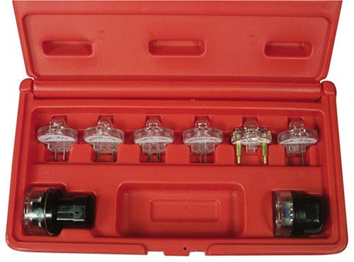
2.) Get a noid light form AutoZone or other auto parts store, or even better a set of them.
This set is from
Amazon product ASIN B00061SH76View: http://www.amazon.com/gp/product/B00061SH76/ref=pd_lpo_sbs_dp_ss_3?pf_rd_p=1944687602&pf_rd_s=lpo-top-stripe-1&pf_rd_t=201&pf_rd_i=B0028QGU6C&pf_rd_m=ATVPDKIKX0DER&pf_rd_r=08WE98XJVCK6FHPESWGY
and costs about $21.
3.) Use the noid light to determine that the injector pulses and isn’t stuck in the on position.
It you have a set of them install all of them and compare the pulse intensity. Install the noid lights, turn the ignition switch to Run and crank the engine. A light that doesn’t pulse and stays on has a short to ground in the computer side of the circuit. That can be either a wiring fault or a failed computer.
If this is the case, remove the passenger side lick panel and disconnect the computer connector.
There is one 10 MM bolt holding it in place. Pull the connector all the way out of the computer so that you can see the computer side pins.
Use the list from the graphic below to find the fuel injector pins for the injectors that didn’t turn the noid light off.
Diagram courtesy of Tmoss & Stang&2birds
4.) Set the multimeter to low scale Ohms and measure between the computer ground located below the computer and the suspect fuel injector pins. You should see greater than 100 K Ohms resistance. If you see less than 100K Ohms, the wiring between the injector and the computer has an internal short to ground and needs service.
Check the harness and look for damage, kinks or frayed spots.
5.) A single noid light that never turns on is either a wiring fault, or a failed computer. Either the injector has no DC power or the computer has failed and cannot switch the injector circuit to ground. Determine if the injector has power by using the multimeter to check for 12 volts on the red wire on the suspect injector connector. No 12 volts and you have a wiring fault.
Check the harness and look for damage, kinks or frayed spots. Check the 10 pin salt & pepper shaker connectors for bent pins, corrosion and damage.
If none of the noid lights flash and you have 12 volts at each injector, check to see that you have good spark. Before you even think about replacing the computer, see step 6.
Next check the fuel injector wiring end to end. Each fuel injector has a red wire (power) and an non-read wire (computer controlled ground). Set the multimeter to low ohms and measure each non red fuel injector wire from
the fuel injector connector to the matching pin on the computer connector. You should see less than 1 Ohm. More than that means a bad connection or bad wiring.
6.) Use an ohmmeter set on the low resistance scale and measure the resistance of each injector across the two contacts inside the electrical connector. You should see between 11-16 ohms. More or less than that is a bad injector. Next measure between either one of the contacts and the metal on the injector body. You should see greater than 100,000 ohms. Don’t hold the metal probe tips with your bare hands when you make this measurement. It will give incorrect results if you do.
Once you have determined that the suspect injectors have good power and good wiring, the computer is the likely suspect, since a ground is required to complete a circuit and make it function. The computer provides the ground: if doesn’t, then the noid light will not flash. If the noid light stays on, the computer has an internal failure.
7) If you have gotten this far, then the problem is likely ignition related. Remember the noid test using all of the noid lights? All of them were supposed to be equally bright. Since you have already tested all the electrical side of the fuel injector circuit, the one remaining common item is the pip sensor inside the distributor. A failing pip sensor, damaged shutter wheel or bent distributor shaft could all cause the pulse delivered to the injectors to be faulty. A bad pip sensor will cause all the injectors not to fire and you will have no spark. Dumping the codes will usually show a code 14.
8) Spark plugs indicate one or more cylinders not firing: use the multimeter to measure the resistance of the spark plug wires. The wires should measure 2000 ohms per foot of length. A 2 foot wire would be 4000 ohms and a 3 foot wire would be 6000 ohms. Some Taylor and Accel wires have metal cores and will measure much less: that’s OK.
Next examine the spark plug wires very carefully for burn spots, cracks and damaged insulation. One good thing to try is to start the engine while the car is a very dark area, open the hood and look for sparks or blue glow. They indicate the electricity is leaking out of the spark plug wires.
Headlight & dashlight problem:
Diagrams courtesy of Tmoss & Stang&2birds
Mustang 5.0 Lights and Radio schematic, by TMoss:
See the following website for some help from Tmoss (diagram designer) & Stang&2Birds (website host) for help on 88-95 wiring
Mustang FAQ - Wiring & Engine Info Everyone should bookmark this site.
94-95 Mustang wiring diagrams
Mustang FAQ - Wiring & Engine Info
Complete computer, actuator & sensor wiring diagram for 91-93 Mass Air Mustangs
http://www.veryuseful.com/mustang/tech/engine/images/91-93_5.0_EEC_Wiring_Diagram.gif
Complete computer, actuator & sensor wiring diagram for 88-91 Mass Air Mustangs
http://www.veryuseful.com/mustang/tech/engine/images/88-91_5.0_EEC_Wiring_Diagram.gif
Ignition switch wiring
http://www.veryuseful.com/mustang/tech/engine/images/IgnitionSwitchWiring.gif
Fuel, alternator, A/C and ignition wiring
http://www.veryuseful.com/mustang/tech/engine/images/fuel-alt-links-ign-ac.gif
O2 sensor wiring harness
http://www.veryuseful.com/mustang/tech/engine/images/mustangO2Harness.gif
Vacuum diagram 89-93 Mustangs
http://www.veryuseful.com/mustang/tech/engine/images/mustangFoxFordVacuumDiagram.jpg
HVAC vacuum diagram
http://www.veryuseful.com/mustang/tech/engine/images/Mustang_AC_heat_vacuum_controls.gif
TFI module differences & pin out
http://www.veryuseful.com/mustang/tech/engine/images/TFI_5.0_comparison.gif
Fuse box layout
http://www.veryuseful.com/mustang/tech/engine/images/MustangFuseBox.gif
Mustang 5.0 Lights and Radio schematic, by TMoss:
http://www.veryuseful.com/mustang/tech/engine/images/mustangFoxLights-Radio_diag.gif
87-92 power window wiring
http://www.veryuseful.com/mustang/tech/engine/images/mustang87-92 PowerWindowWiring.gif
93 power window wiring
http://www.veryuseful.com/mustang/tech/engine/images/mustang93PowerWindows.gif
T5 Cutaway showing T5 internal parts
http://www.veryuseful.com/mustang/tech/engine/images/5_Speed_Cutaway_Illustrated.jpg
Visual comparison of the Ford Fuel Injectors, picture by TMoss:
http://www.veryuseful.com/mustang/tech/engine/images/Ford_Injector_Guide.jpg