Engine Codes 81, 82, 85 and 41 - Where to start. 5.0HO/AOD transplanted into '67

Blue_67Vert

Member
Sep 25, 2016
24
6
13
KOEO codes: 81, 82, 85 KOER codes:41

This is a 5.0HO and AOD in a '67. It runs OK if I'm just cruising or get into the throttle slowly. But I get a small back fire sometimes and if I go WOT, I get no good response.
I have no smog equipment (smog pump or cats). I do have the EGR plumbed.
I had the BAP sensor dangling around behind the engine. I meant to come back and mount it properly on the firewall but completely forgot until now. It is now temporarily wired to my shocktower support brace.

Should test the BAP sensor? If so, how do I do that?
Should I start chasing vacuum leaks?
Where do I start?

EDIT 2: Deleted first edit. As this is MAF the BAP reads atmospheric pressure and correctly does not have a vacuum line.
 
Last edited:
  • Sponsors (?)


It is MAF. ECU is A9P. The wiring is some Hypertech Speed Density conversion harness. I added the MAF harness and repinned to HO firing order. Yes I did the install myself. Timing is at 11* BTDC set with the PIP out.

I'll install new vacuum hoses next.
Both O2 sensors are new (Bosch).
 
Last edited:
ALLLRITTTYTHEN!
I am glad to read that, so many times we get the 'why does it not run right 'cause I bought it this way?'
Could use a couple more degrees advance but don't change it yet, get to that later.
go here: http://forums.stangnet.com/showthread.php?t=698148
This will show you how to test some things and how stuff works, since you did the work yourself I figure you are not the average person coming here seeking help.
Intake backfire usually means lean or timing issue and a vacuum leak could cause it, have you put a vacuum gauge to it?
And post up pics, the engine compartment specifically but the whole car in general, fell free to include any pets or kids you may have. Bonus points it they are holding a wrench and not a phone (the kids that is, pets can hold anything they want)
Sometimes an engine pic will reveal a possible issue.
Ok, reality is we just like to see how good a job you did,
 
Thanks for the link. I've actually been through it a few times before posting.
Should I just start running that whole list? I was hoping with the codes posted I'd get a starting point.
I have a vacuum pump with a guage that I used to vacuum bleed brakes.
How would I use it to check for vacuum leaks?

I'll share pics even if she's not pic worthy yet. I'm still trying to shake down mechanicla problems and get her driveable before I clean up the wiring and tidy up the engine compartment.

Once glaring problem is the open cone filter in the engine bay. Not sure if that's an issue here. Ultimately I will be running it under the battery tray and to the front of the radiator support.

While I did do all the work myself every step has been a learning experience. I am bit out of my depth which why I'm here asking questions.

More info:
Engine related is mostly all used donor parts.
Harness is new as noted above.
Fuel tank, pump, filter, supply side fuel lines are new.
I don't have a vacuum tree. The port normally used for that goes directly to my brake booster.
I made up a bracket for the belt tensioner. Pep Boys didn't have belt that would fit but she seems to be holding steady temperature with the short belt so far. Leaving the bracket in place for now.
I had to drill out the holes in the TPS to adjust it.
 

Attachments

  • IMG_3100.jpg
    IMG_3100.jpg
    145.3 KB · Views: 166
  • IMG_3211.jpg
    IMG_3211.jpg
    223.8 KB · Views: 164
The air filter can cause idle surging issues mounted directly to the maf. That is not your problem, a back fire in the intake is a lean condition. Possible causes are vacuum leak or ignition or fuel related.
The computer has grounds that are very important. One (on a fox body) small wire goes from the negative battery cable to the fender apron by the solenoid then connects to a black cylindrical connector then into the wire harness, is this present in your car?
I would also check to see if the timing advances when the rpms are raised, you will have to mark the balancer for up to 30* advance.
Another thing would be fuel pressure, do you have the schrader valve and a fuel pressure regulator like a stock fox would have? If yes, check fuel pressure with the vacuum line off and plugged, should be 40-43 lbs, vacuum line connected should be 32-4 lbs.
Being this is a conversion will make this condition hard to diagnose.
 
I do not have a black cylindrical connector on the ECU ground wire.
ECU pin 20 is grounded to the inside of the body and bare wire goes into a wrapped section of the harness.
ECU 40 and 60 also go into a wrapped section of the harness. A ground wire coming out of the wrapped section of the harness is grounded to the back of the passenger side cylinder head which is grounded to the firewall with a braided cable.
I did not unwrap the harness to see where each wire goes individually but did continuity tests on every pin out.
My battery is on the passenger side and is grounded to the front of the engine block. A 2nd small wire from the battery negative lug I have grounded to the drivers side frame rail of the unibody.

Timing idle at 14* and increases to 30* with some increased RPM. Car was in Park and my some blipped throttle.

Fuel pressure is at 32-34 with hose connected to fuel pressure regulator. 40 PSI with the vacuum pulled and plugged.

Before checking timing and fuel pressure above I went for short spin today. I noticed a very bad gas smell when I pulled back into the driveway. I had a leak at a short section of hose that connects my fuel pump to the hard fuel line. A hose clamp had come loose. I don't think this was an issue when I made the original post but sharing just in case I am wrong and it is relevant.

I also checked all of my vacuum hoses and they are in good condition. Unfortunately I misplaced the nozzle to my propane bottle that I wanted to use to hunt vacuum leaks.

And thank for taking the time to read my posts and providing feedback. It is very much appreciated.
 
It appears that, at least to me you have a handle on the wiring, so lets go to the mechanical side, grab a vacuum gauge and zip tie it someplace temporarily and take it for a ride, try to make it back fire taking note of what happens to the vacuum when it does.
I didn't ask but what valve train parts are you using, stock?
There is a possibility a valve is adjusted too tight or hanging up.
 
Vacuum goes to zero at WOT. No movement on the vacuum gauge when I hear it back fire. After car was warm from the drive, vacuum was at 14 idling in Park.
Engine and AOD are stock 5.0HO stuff.
I have shorty headers, no power steering nor AC.
 
KOEO codes: 81, 82, 85 KOER codes:41
Here they are in numerical order....

The code 41 is the first one to chase since it may be part of the backfire problem.

Code 41 or 91. Or 43 Three digit code 172 or 176
- O2 sensor indicates system lean. Look for a vacuum leak or failing O2 sensor.

Revised 01 Sep 2019 1.) To emphasize do not attempt to measure the O2 sensor resistance. Disconnect the O2 sensor from the wiring before doing any resistance checking of the sensor to computer wiring.

Code 41 is the passenger side sensor, as viewed from the driver's seat.
Code 91 is the driver side sensor, as viewed from the driver's seat.

Code 172 is the passenger side sensor as viewed from the driver's seat.
Code 176 is the driver side sensor, as viewed from the driver's seat.

Code 43 is not side specific according to the Probst Ford Fuel injection book.

The computer sees a lean mixture signal coming from the O2 sensors and tries to compensate by adding more fuel. Many times the end result is an engine that runs pig rich and stinks of unburned fuel.

The following is a Quote from Charles O. Probst, Ford fuel Injection & Electronic Engine control:

"When the mixture is lean, the exhaust gas has oxygen, about the same amount as the ambient air. So the sensor will generate less than 400 Millivolts. Remember lean = less voltage.
When the mixture is rich, there's less oxygen in the exhaust than in the ambient air , so voltage is generated between the two sides of the tip. The voltage is greater than 600 millivolts. Remember rich = more voltage.
Here's a tip: the newer the sensor, the more the voltage changes, swinging from as low as 0.1 volt to as much as 0.9 volt. As an oxygen sensor ages, the voltage changes get smaller and slower - the voltage change lags behind the change in exhaust gas oxygen.

Because the oxygen sensor generates its own voltage, never apply voltage and never measure resistance of the O2 sensor. Before checking the O2 sensor circuit wiring resistance, disconnect the O2 sensor from the rest of the circuit wiring. To measure voltage signals, use an analog voltmeter with a high input impedance, at least 10 megohms. Remember, a digital voltmeter will average a changing voltage. End Quote

Testing the O2 sensors 87-93 5.0 Mustangs

Measuring the O2 sensor voltage at the computer will give you a good idea of how well they are working. You'll have to pull the passenger side kick panel off to gain access to the computer connector. Remove the plastic wiring cover to get to the back side of the wiring. Use a safety pin or paper clip to probe the connections from the rear.


Disconnect the O2 sensor from the harness and use the body side O2 sensor harness as the starting point for testing. Do not measure the resistance of the O2 sensor, you may damage it. Resistance measurements for the O2 sensor harness are made with one meter lead on the O2 sensor harness and the other meter lead on the computer wire or pin for the O2 sensor.
Computer wiring harness connector, computer side.
88243.gif


Backside view of the computer wiring connector:
71316.gif


87-90 5.0 Mustangs:
Computer pin 43 Dark blue/Lt green – LH O2 sensor
Computer pin 29 Dark Green/Pink – RH O2 sensor

The computer pins are 29 (RH O2 with a dark green/pink wire) and 43 (LH O2 with a dark blue/lt green wire). Use the ground next to the computer to ground the voltmeter. The O2 sensor voltage should switch between .2-.9 volt at idle.


91-93 5.0 Mustangs:
Computer pin 43 Red/Black – LH O2 sensor
Computer pin 29 Gray/Lt blue – RH O2 sensor

The computer pins are 29 (RH O2 with a Gray/Lt blue wire) and 43 (LH O2 with a Red/Black wire). Use the ground next to the computer to ground the voltmeter. The O2 sensor voltage should switch between .2-.9 volt at idle.


94-95 5.0 Mustangs; note that the 94-95 uses a 4 wire O2 sensor.
The computer pins are 29 (LH O2 with a red/black wire) and 27 (RH O2 with a gray/lt blue wire). Use pin 32 (gray/red wire) to ground the voltmeter. . The O2 sensor voltage should switch between .2-.9 volt at idle.


Note that all resistance tests must be done with power off. Measuring resistance with a circuit powered on will give false readings and possibly damage the meter. Do not attempt to measure the resistance of the O2 sensors, it may damage them.

Testing the O2 sensor wiring harness
Most of the common multimeters have a resistance scale. Be sure the O2 sensors are disconnected and measure the resistance from the O2 sensor body harness to the pins on the computer. Using the Low Ohms range (usually 200 Ohms) you should see less than 1.5 Ohms.


87-90 5.0 Mustangs:
Computer pin 43 Dark blue/Lt green – LH O2 sensor
Computer pin 29 Dark Green/Pink – RH O2 sensor
Disconnect the connector from the O2 sensor and measure the resistance:
From the Dark blue/Lt green wire in the LH O2 sensor harness and the Dark blue/Lt green wire on the computer pin 43
From the Dark Green/Pink wire on the RH O2 sensor harness and the Dark Green/Pink wire on the computer pin 29


91-93 5.0 Mustangs:
Computer pin 43 Red/Black – LH O2 sensor
Computer pin 29 Gray/Lt blue – RH O2 sensor
Disconnect the connector from the O2 sensor and measure the resistance:
From the Red/Black wire in the LH O2 sensor harness and the Red/Black wire on the computer pin 43
From the Gray/Lt blue wire on the RH O2 sensor harness and the Gray/Lt blue wire on the computer pin 29

94-95 5.0 Mustangs:
Computer pin 29 Red/Black – LH O2 sensor
Computer pin 27 Gray/Lt blue – RH O2 sensor
From the Red/Black wire in the LH O2 sensor harness and the Red/Black wire on the computer pin 29
From the Dark Green/Pink Gray/Lt blue wire on the RH O2 sensor harness and the Gray/Lt blue wire on the computer pin 27


There is a connector between the body harness and the O2 sensor harness. Make sure the connectors are mated together, the contacts and wiring are not damaged, and the contacts are clean and not coated with oil.

The O2 sensor ground (orange wire with a ring terminal on it) is in the wiring harness for the fuel injection wiring. I grounded mine to one of the intake manifold bolts

Check the fuel pressure – the fuel pressure is 37-41 PSI with the vacuum disconnected and the engine idling. Fuel pressure out of range can cause the 41 & 91 codes together. It will not cause a single code, only both codes together.

Make sure you have the proper 3 wire O2 sensors. Only the 4 cylinder cars used a 4 wire sensor, which is not compatible with the V8 wiring harness. The exception is that the 94-95 uses a 4 wire O2 sensor.

Replace the O2 sensors in pairs if replacement is indicated. If one is weak or bad, the other one probably isn't far behind.

Code 41 can also be due to carbon plugging the driver’s side Thermactor air crossover tube on the back of the engine. The tube fills up with carbon and does not pass air to the driver’s side head ports. This puts an excess amount of air in the passenger side exhaust and can set the code 41. Remove the tube and clean it out so that both sides get good airflow: this may be more difficult than it sounds. You need something like a mini rotor-rooter to do the job because of the curves in the tube. Something like the outer spiral jacket of a flexible push-pull cable may be the thing that does the trick.

If you get only code 41 and have changed the sensor, look for vacuum leaks. This is especially true if you are having idle problems. The small plastic tubing is very brittle after many years of the heating it receives. Replace the tubing and check the PVC and the hoses connected to it.

Complete computer, actuator & sensor wiring diagram for 94-95 Mustangs
94-95_5.0_EEC_Wiring_Diagram.gif


Complete computer, actuator & sensor wiring diagram for 91-93 Mass Air Mustangs
91-93_5.0_EEC_Wiring_Diagram.gif


Complete computer, actuator & sensor wiring diagram for 88-90 Mass Air Mustangs
88-91_5.0_EEC_Wiring_Diagram.gif


Code 81 – Secondary Air Injection Diverter Solenoid failure AM2. The solenoid valve located on the back side of the passenger side wheel well is not functional. Possible bad wiring, bad connections, missing or defective solenoid valve. Check the solenoid valve for +12 volts at the Red wire and look for the Lt Green/Black wire to switch from +12 volts to 1 volt or less. The computer controls the valve by providing a ground path on the LT Green/Black wire for the solenoid valve.

With the with the ignition on, look for 12 volts on the red wire on the solenoid connector. No 12 volts and you have wiring problems.

With the engine running, stick a safety pin in the LT Green/Black wire for the solenoid valve & ground it. That should turn the solenoid on and cause air to flow out the port that goes to the pipe connected to the cats. If it doesn't, the valve is bad. If it does cause the airflow to switch, the computer or wiring going to the computer is not signaling the solenoid valve to open.

Putting the computer into self test mode will cause the solenoid valve to toggle. If you listen carefully, you may hear it change states.


Code 82 – Secondary Air Injection Diverter Solenoid failure AM1. Possible bad wiring, bad connections, missing or defective solenoid valve. Check the solenoid valve for +12 volts at the Red wire and look for the Red/White wire to switch from +12 volts to 1 volt or less. The computer controls the valve by providing a ground path on the Red/White wire for the solenoid valve

With the engine running, stick a safety pin in the Red/White wire for the solenoid valve & ground it. That should turn the solenoid on and cause air to flow out the port that goes to the pipe connected to the heads. If it doesn't, the valve is bad. If it does cause the airflow to switch, the computer or wiring going to the computer is not signaling the solenoid valve to open.

Both 81 & 82 codes usually mean that some uneducated person removed the solenoid control valves for the Thermactor Air system in an attempt to make the car faster. It doesn't work that way: no working control valves can cause the cat converters to choke and clog. If you do not have cat converters on the car, you can ignore the 81 & 82 codes.


Code 85 CANP solenoid - The Carbon Canister solenoid is inoperative or missing.

Revised 11 –Jan_2015 to add warning about vacuum leaks due to deteriorated hose or missing caps on vacuum lines when the solenoid is removed.

Check vacuum lines for leaks and cracks. Check electrical wiring for loose connections, damaged wiring and insulation. Check solenoid valve operation by grounding the gray/yellow wire to the solenoid and blowing through it.
The computer provides the ground for the solenoid. The red wire to the solenoid is always energized any time the ignition switch is in the run position.

If you disconnected the carbon canister and failed to properly cap the vacuum line coming from under the upper intake manifold, you will have problems. You will also have problems if the remaining hose coming from under the upper intake manifold or caps for the vacuum line are sucking air.

Charcoal canister plumbing - one 3/8" tube from the bottom of the upper manifold to the rubber hose. Rubber hose connects to one side of the canister solenoid valve. Other side of the solenoid valve connects to one side of the canister. The other side of the canister connects to a rubber hose that connects to a line that goes all the way back to the gas tank. There is an electrical connector coming from the passenger side injector harness near #1 injector that plugs into the canister solenoid valve. It's purpose is to vent the gas tank. The solenoid valve opens at cruse to provide some extra fuel. The canister is normally mounted on the passenger side frame rail near the smog pump pulley.

Connecting the gas tank vent line directly to the intake manifold will result in fuel vapor being constantly sucked into the intake manifold. There is unmetered fuel that the computer cannot adjust for. The result is poor idle and poor fuel economy.

attachments\58191


It does not weigh but a pound or so and helps richen up the cruse mixture. It draws no HP & keeps the car from smelling like gasoline in a closed garage. So with all these good things and no bad ones, why not hook it up & use it?


The purge valve solenoid connector is a dangling wire that is near the ECT sensor and oil filler on the passenger side rocker cover. The actual solenoid valve is down next to the carbon canister. There is about 12"-16" of wire that runs parallel to the canister vent hose that comes off the bottom side of the upper intake manifold. That hose connects one port of the solenoid valve; the other port connects to the carbon canister.

The purge valve solenoid should be available at your local auto parts store.

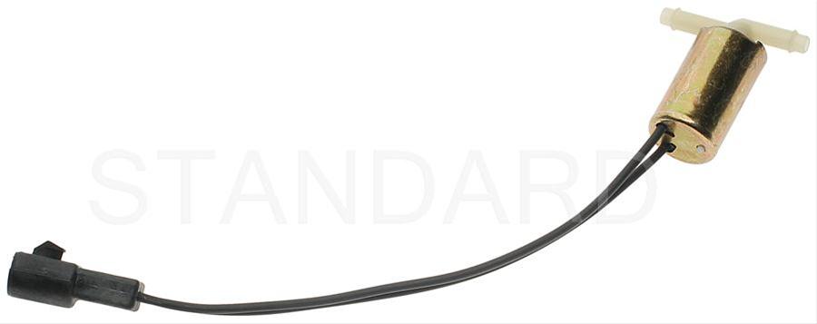
Purge valve solenoid:
smp-cp402_df_xl.jpg


The carbon canister is normally mounted on the passenger side frame rail near the smog pump pulley.
Carbon Canister:
903_AIRTEX%20_pct_2F%20WELLS_7310014_1.jpg
 
@jrichker Thanks for the reply. I actually read through all of that earlier.

Regarding code 41 - Both O2 sensors are new Bosch parts. Should I test them anyway?

As for performing the actual tests, if I am understanding correctly I would conduct 2 tests:
1) Voltage at PIN 29 using an analog meter (engine running)
2) Resistance of the harness from O2 sensor connector to the ECU pin 29 (power off).

The O2 sensors are new and the EEC-IV harness is new. I have just confirmed the connection to be clean and tight. I even cleaned the pins with alcohol while I was at it.

I have no thermactor tube.

Regarding codes 81, 82, 85, I have no smog equipment other than EGR.

@General karthief On the subject of EGR, I went out and put 5 in of vacuum on the EGR valve and the engine did noticeably stumble.
Measuring off the hose going to the EGR Vacuum Regulator (EVR) I have 15in of manifold vacuum at idling in park from the manifold.
Measuring vacuum from the EGR side of the EVR I have no vacuum at all even if I blip the throttle.
I misplaced my tachometer and haven't installed it yet. When I say blip I don't know what RPM.

What are we looking to achieve with the EGR block off?
And should I replace the EVR?
 
Last edited:
Some basic theory to clarify how things work will be helpful…

EGR System theory and testing

Revised 29-Sep-2013 to add code definitions for EGR sensor and EVR regulator.

The EGR shuts off at Wide Open Throttle (WOT), so it has minimal effect on performance. The addition of exhaust gas drops combustion temperature, increases gas mileage and reduces the tendency of the engine to ping. It can also reduce HC emissions by reducing fuel consumption. The primary result of EGR usage is a reduction in NOx emissions. It does this by reducing the amount of air/fuel mixture that gets burned in the combustion process. Less air from the intake system means less air to mx with the fuel, so the computer leans out the fuel delivery calculations to balance things out. This reduces combustion temperature, and the creation of NOx gases. The reduced combustion temp reduces the tendency to ping.

The computer shuts down the EGR system when it detects WOT (Wide Open Throttle), so the effect on full throttle performance is too small to have any measurable negative effects.

The EGR system has a vacuum source (line from the intake manifold) that goes to the EVR, computer operated electronic vacuum regulator. The EVR is located on the back of the passenger side shock strut tower. The computer uses RPM, Load. and some other factors to tell the EVR to pass vacuum to open the EGR valve. The EGR valve and the passages in the heads and intake manifold route exhaust gas to the EGR spacer (throttle body spacer). The EGR sensor tells the computer how far the EGR valve is open. Then computer adjusts the signal sent to the EVR to hold, increase or decrease the vacuum. The computer adds spark advance to compensate for the recirculated gases and the slower rate they burn at.

The resistor packs used to fool the computer into turning off the CEL (Check Engine Light) off are a bad idea. All they really do is mess up the data the computer uses to calculate the correct air/fuel mixture. You can easily create problems that are difficult to pin down and fix.

egr-system-legal-size-paper-55-gif.gif


Troubleshooting:
There should be no vacuum at the EGR valve when at idle.

If there is, the EVR (electronic vacuum regulator) mounted on the backside of the passenger side wheelwell is suspect. Check the vacuum line plumbing to make sure the previous owner didn’t cross the vacuum lines.

Diagram courtesy of Tmoss & Stang&2birds. (the diagram says 88 GT, but the EGR part is the same for 86-93 Mustangs)
88Stang5.0Vacuum.gif


The EGR sensor is basically a variable resistor, like the volume control on a radio. One end is 5 volt VREF power from the computer (red/orange wire). One end is computer signal ground (black/white), and the middle wire (brown/lt green) is the signal output from the EGR sensor. It is designed to always have some small voltage output from it anytime the ignition switch is the Run position. That way the computer knows the sensor & the wiring is OK. No voltage on computer pin 27 (brown/lt green wire) and the computer thinks the sensor is bad or the wire is broken and sets code 31. The voltage output can range from approximately .6-.85 volt. A defective or missing sensor will set codes 31 (EVP circuit below minimum voltage) or 32 ( EGR voltage below closed limit).

The EVR regulates vacuum to the EGR valve to maintain the correct amount of vacuum. The solenoid coil should measure 20-70 Ohms resistance. The regulator has a vacuum feed on the bottom which draws from the intake manifold. The other vacuum line is regulated vacuum going to the EGR valve. One side of the EVR electrical circuit is +12 volts anytime the ignition switch is in the run position. The other side of the electrical circuit is the ground path and is controlled by the computer. The computer switches the ground on and off to control the regulator solenoid. A defective EVR will set codes 33 (insufficient flow detected), 84 (EGR Vacuum Regulator failure – Broken vacuum lines, no +12 volts, regulator coil open circuit, missing EGR vacuum regulator.)


EGR test procedure courtesy of cjones

To check the EGR valve:
Bring the engine to normal temp.

Connect a vacuum pump to the EGR Valve or see the EGR test jig drawing below. Connnect the test jig or to directly to manifold vacuum.

Do not connect the EGR test jig to the EVR (Electronic Vacuum Regulator).


Apply 5in vacuum to the valve. Using the test jig, use your finger to vary the vacuum

If the engine stumbled or died then EGR Valve and passage(there is a passageway through the heads and intake) are good.

If the engine did NOT stumble or die then either the EGR Valve is bad and/or the passage is blocked.

If the engine stumbled, connect EGR test jig to the hose coming off of the EGR Valve.
Use your finger to cap the open port on the vacuum tee.
Snap throttle to 2500 RPM (remember snap the throttle don't hold it there).
Did the vacuum gauge show about 2-5 in vacuum?
If not the EVR has failed

EGR test jig
egr-test-jig-gif.gif


To test the computer and wiring to the computer, you can use a test light across the EVR wiring connectors and dump the codes. When you dump the codes, the computer does a self test that toggles every relay/actuator/solenoid on and off. When this happens, the test light will flicker. If the test light remains on the computer or the wiring is suspect.

To check the EVR to computer wiring, disconnect the EVR connector and connect one end of the Ohmmeter to the dark green wire EVR wiring. Remove the passenger side kick panel and use a 10 MM socket to remove the computer connector from the computer. Set the Ohmmeter to high range and connect the other ohmmeter lead to ground. You should see an infinite open circuit indication or a reading greater than 1 Meg Ohm. If you see less than 200 Ohms, the dark green wire has shorted to ground somewhere.
 
I put a vacuum gauge on a T between the EVR and EGR. I didn't get any vacuum between the EVR and EGR when I hit the throttle. But I also didn't get any EVR codes. Should I replace the EVR?

I feel like with all my goofing around with the EVR/EGR vacuum lines I should clear codes, run the car again and pull codes again.

Before I do that I decided to pull codes again.
KOEO: 81, 82, 85 again as expected since I don't have smog equipment in place.
In memory: 22, 34 I feel like this is related to me getting vacuum readings and testing the EGR valve with a vacuum pump.

Engine Running codes: 21, 94, 44.
21, (ECT) sensor out of Self-Test range. This is new.
94 and 44 I suspect related because I have no smog equipment. But strange I did not get those before.
41 is gone. Not sure what this means. however, I did reseat the O2 sensor harness connectors and clean the pins.

Maybe I didn't run the car long enough before pulling codes the when I made the original post. I think I had run the car about 20 mins.

Should I clear codes and run the car longer tomorrow? Or just keep plugging away?
 
Last edited: