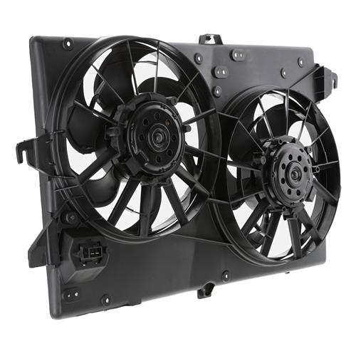
Electric fan relays

7991LXnSHO

wanna catch the space herp
10 Year Member
Sep 1, 2010
7,388
3,099
194
Kearney, NE
I have been reading about a Bosch 75A related for running the OEM style of fans. I was at Menards and saw what might be a cheaper, effective alternative. Electric start mowers have a smaller version of the Ford starter relay (aka solenoid). I am sure the amp rating of a starter motor for a 20+ hp engine is at least 75 amps. I am not sure about the constant duty cycle rating on it. Has anyone used these for another purpose than starting yard products or motorized toys?
Also, is this link for the right Bosch relay?
 

Attachments

  • 9889BABD-5172-4B3F-9548-5A1DB86277B4.jpeg
    9889BABD-5172-4B3F-9548-5A1DB86277B4.jpeg
    336.6 KB · Views: 101
  • Sponsors (?)


I just wired up my contour fans with 2 30a relays. 1 relay for each fan. Its a simple key on fan on operation. (Coolant sensor red wire) The relays are $7 a pop on ebay. X2= $15. Add $15 in 10ga wiring from local oreillys, $10 for terminal assortment kit, $5 shrink wrap assortment from harbor/elec tape. $6 solder gun. $6 solder. Fans $50 at JY. Make brackets, $2 a pc out of the thin mending plate, easy to work with. X4 so $8. Bolts/nuts/washers/lock washers, Zipties, Thats about it. $120. Vs $3-400.

My car idled forever and never got over 210 ish. (@ 92+ degree ambient) Felt peppier also with the 5hp+ parasitic loss that got dropped.

I know this has nothing to do with the question, but i want to brag about my achievement. Lol.
 
I believe I have the one in the photo (Bosch/Tyco), but this appears to be the same relay for a little cheaper price. I can go check later.

Amazon product ASIN B0117FAGVOView: https://www.amazon.com/Bosch-332-002-168-0332002168/dp/B0117FAGVO/ref=asc_df_B0117FAGVO/?tag=bingshoppinga-20&linkCode=df0&hvadid=&hvpos=&hvnetw=o&hvrand=&hvpone=&hvptwo=&hvqmt=e&hvdev=c&hvdvcmdl=&hvlocint=&hvlocphy=&hvtargid=pla-4584276296427787&psc=1


I bought mine 20 years ago and it still works flawlessly today. I only run a single fan. I wired it so that my aftermarket fan controller (which only has a 30A relay) just turned the 75A relay on rather than directly powering the fan. I've measured the draw of my 94-95 Sn95 efan and it was only 35AMPs continuous.

When I go Megasquirt, I plan on using a volvo PWM fan controller with the MS3x to control the fan.


There are many many ways to skin a cat here in terms of fan control.
 
Last edited:
  • Like
Reactions: 1 user
Leash sells a nice relay module which can be used for e fans. Comes with a 70a relay, and has provisions for a fuse so you don’t need to run one inline.


I ran one of the big 100 amp relay when I required the sn95 fan I used. They’re the ones with the large pins on them, but they’re comparable to a standard size relay. Got it off amazon for around $12 for 2.
 
  • Like
Reactions: 1 users
I believe I have the one in the photo (Bosch/Tyco), but this appears to be the same relay for a little cheaper price. I can go check later.

Amazon product ASIN B0117FAGVOView: https://www.amazon.com/Bosch-332-002-168-0332002168/dp/B0117FAGVO/ref=asc_df_B0117FAGVO/?tag=bingshoppinga-20&linkCode=df0&hvadid=&hvpos=&hvnetw=o&hvrand=&hvpone=&hvptwo=&hvqmt=e&hvdev=c&hvdvcmdl=&hvlocint=&hvlocphy=&hvtargid=pla-4584276296427787&psc=1


I bought mine 20 years ago and it still works flawlessly today. I only run a single fan. I wired it so that my aftermarket fan controller (which only has a 30A relay) just turned the 75A relay on rather than directly powering the fan. I've measured the draw of my 94-95 Sn95 efan and it was only 35AMPs continuous.

When I go Megasquirt, I plan on using a volvo PWM fan controller with the MS3x to control the fan.


There are many many ways to skin a cat here in terms of fan control.
That's almost the same one as the -156. Don't know what the difference is.
 
So is the diode is to prevent the motor working like a generator going down the highway or after the car is shut off?
The small engine solenoid is much cheaper, but if this is so reliable, the cost is not an issue.
Wrong answer...

Using a diode as a dampener in automotive circuits:

Theory of operation:
The diode acts as a surge absorber or one way gate. Anytime you turn the power off an inductive load (coil, motor, solenoid, etc) the collapse of the magnetic field creates a voltage spike of opposite polarity to the voltage applied. The positive wire sees a negative spike and the negative wire sees a positive spike. The diode is wired backwards so that it does not conduct during normal forward operation. When the magnetic field collapses, the diode sees the reverse polarity spike and clamps it. This prevents the spike from possibly damaging the rest of the electronics in the car.
When used to clamp spikes in automotive circuits, connect the lead that comes from the end of the diode that has the band on it to the positive side of the circuit. Connect it the other way and you will make smoke.

Diode markings
attachments\586744\


A properly functioning diode will measure very high resistance or open circuit in one direction. Reverse the meter leads and it will measure a lower resistance.

attachments\50089\
 
So is the diode is to prevent the motor working like a generator going down the highway or after the car is shut off?
The small engine solenoid is much cheaper, but if this is so reliable, the cost is not an issue.

It’s been in my car damn near 20 years. I realize the car sat for 10 of those, but the relay also sat and aged as well and I’ve never had a hiccup with it. I’m running about 35a through it
 
Why the sarcasm, J.? I know how a diode works. I asked what it did in this circuit and appreciate the rest of the answer.


Wrong answer...

Using a diode as a dampener in automotive circuits:

Theory of operation:
The diode acts as a surge absorber or one way gate. Anytime you turn the power off an inductive load (coil, motor, solenoid, etc) the collapse of the magnetic field creates a voltage spike of opposite polarity to the voltage applied. The positive wire sees a negative spike and the negative wire sees a positive spike. The diode is wired backwards so that it does not conduct during normal forward operation. When the magnetic field collapses, the diode sees the reverse polarity spike and clamps it. This prevents the spike from possibly damaging the rest of the electronics in the car.
When used to clamp spikes in automotive circuits, connect the lead that comes from the end of the diode that has the band on it to the positive side of the circuit. Connect it the other way and you will make smoke.

Diode markings
attachments\586744\


A properly functioning diode will measure very high resistance or open circuit in one direction. Reverse the meter leads and it will measure a lower resistance.

attachments\50089\
 
Why the sarcasm, J.? I know how a diode works. I asked what it did in this circuit and appreciate the rest of the answer.
No sarcasm or insult was intended.

Most of the people here don't understand electricity and I have limited ways of understanding the depth of electrical knowledge. Therefore I spell out the details to try to give them some understanding of how it works.
 
  • Like
Reactions: 1 user
No sarcasm or insult was intended.

Most of the people here don't understand electricity and I have limited ways of understanding the depth of electrical knowledge. Therefore I spell out the details to try to give them some understanding of how it works.
you are very helpful to the 'electronically impaired' like myself. The only thing I'm sure is electricity is not like water and does not always run downhill. :jester:
 
  • Like
Reactions: 1 user
No sarcasm or insult was intended.

I must have read “wrong answer” in the tone of my teenagers having a bad day.

The voltage spike from a collapsing field is what induces a higher, spark capable voltage spike in the secondary windings of an ignition coil.
The two diodes on the relay schematic diagram are both on the trigger side (terminal 86). It seems that a high current capacity diode on the load side (terminal 87) would be a more effective if the open points is not enough to clamp the voltage spike.

What I not understand, and may not be fully applicable here, are reports of electric fans causing run on in points and HEI carbureted cars. How a fan’s reverse voltage spike or generated power can overcome the open points and continue to power the ignition without being miswired Is an explanation I would like to hear. If the relay with the two diodes in the trigger side fixes this, I need to “relay” the info.