
I have no speedometer, fuel gauge isn't working, and the turn isn't aluminating on dash or the click noise how ever is blinking at the bulbs
You are using an out of date browser. It may not display this or other websites correctly.
You should upgrade or use an alternative browser.
You should upgrade or use an alternative browser.
Fuel Gauge, Speed O, And Left Turn Signal
- Thread starter teebluestang
- Start date
-
Sponsors (?)
The speedometer problem is probably a bad cable or drive gear.
Drive gear location on the transmission:

Speedometer cable replacement for 87-93 Mustangs
Revised 11 Mar-2015 to add tip on what to look for when there is a bouncing speedometer.
How the speedometer works:
The indicator pointer has no direct connection to the speedo cable. It uses a drum with magnets on it to couple to the pointer. The drum turns and tries to twist the circular steel disk that is mounted on the pointer spindle. The magnetic force is all that connects the drum to the circular disk. There is very little clearance between the disk and drum, only a few thousands of an inch.
Lubrication warning
Use a graphite based lubricant for the speedo cable. It is available at most auto parts stores in a very small tube. Lubricate only the lower half of the cable. The reason for this is that if you use too much lubricant, it works its way up into the speedo head and gets between the rotating magnet and the disk. This causes the speedo to seize up and may wring the indicator needle off the indicator spindle. You may be able to fix things up with non-flammable brake parts cleaner to clean the disk and magnet assembly. Count on replacing the current cable and housing with a new cable and housing. You need to do this to prevent the excess lubricant from causing it to fail again.
A speedometer that bounces around is either a cable problem (top cause) or a speedometer drive gear that is chewed up. When you remove the cable drive end, check the teeth on the driven gear (the one attached to the cable) or the drive gear (the one on the transmission output shaft) Late Model Restoration (http://www.latemodelrestoration.com/products/79-93-Mustang-Transmission-Speedometer-Correction) has a complete range of replacement speedometer gear sets.
Speedometer cable replacement .
Note: All 89-93 cars have a VSS sensor even if they do not have cruise control. The 87-88 only have a VSS sensor if they have cruise control.
Speedo cable housing assembly without cruise control:

The VSS equipped cars have a speedo cable with a different fitting on the transmission end of the cable. It is the fitting on the LH side of the following picture.
Speedo cable housing assembly with cruise control

Preparation: if you are only going to replace the inner part of the speedo cable, get lots of newspaper or a painter’s drop cloth to cover the inside front of the car. About the time you have the dirty, oily speedo cable core all over your lap and the inside of the car, you will thank me for this suggestion.
Replacing only the inner cable: see steps 1- 6, 12, 13, 17-21
Replacing the housing and inner cable as an assembly: see steps 1-11, 13-21
Inside the car:
1.) Remove the shield around the steering column that covers the ignition switch & turn indicator switch.
2.) You now have access to the two screws that hold the lower part of the cluster housing in place. Remove them and place them in a zip bag.
3.) Use a stubby or an offset Philips screwdriver to remove the two screws on the top of the cluster housing. The screws are up close to the windshield, so they can be hard to get at.
4.) The cluster housing will now slide forward: depending on your particular car, you may or may not have to disconnect the wiring for the headlights, hazard lights, or cluster wiring. All of the wiring uses plastic connectors with plastic spring clips on them. To release the connectors, lift the plastic clips and pull straight back.
5.) The speedo cable is secured in the speedo head by a white plastic clip. Depress the clip or squeeze it and pull the cable out of the speedo head. This can be tricky, but it will come out if you have the white clip depressed enough.
Speedo head cable clip
Photos courtesy of Almost Stock


6.) With speedo cable removed from the speedo head, try twisting the cable end with your fingers. If it turns more than 1/4 turn, the cable may either be broken or you have damage at the other end where the cable mates to the VSS sensor or speedo pickup gear in the transmission.
Outside the car, replacing the cable housing assembly.
The following steps are necessary only if you plan on replacing the cable & cable housing assembly.
7.) If you are going to the replace the cable housing, the next step is important. Tie a study string or wire to the VSS sensor end of the cable housing. This string or wire is to be used to fish the cable housing back through the maze of wires that is under the dash. If all you are going to do is replace the inner cable, you can omit this step.
8.) Jack up the car, all 4 tires must be off the ground. Place jackstands under the car for safety.
9.) Locate the VSS sensor on the driver’s side of the transmission tailshaft housing. The speedo cable housing will be secured in the VSS sensor with a hairpin clip Do not remove the clip!!!: The hairpin clip stays in place. If you remove it, the odds are that you will not be able to get the cable to stay in place on re-installation. Pull firmly straight back on the cable housing and it will come out. A considerable amount of effort may be required to get the cable out of the VSS sensor, but it will pull out.
10.) Release the cable housing from the clips that secure it to the car body.
Inside the car:
11.) If all you are going to do is replace the inner cable, you can omit this step.
The housing assembly can then be pulled out and the fish string or wire can be removed from the old cable housing and secured to the new one.
12.) You can omit this step if you are replacing the cable & cable housing assembly.
The inner cable can be removed by pulling it out of the housing assembly. Watch out for the lubricant so that you don’t get it on the car’s interior.
13.) You can omit this step if you are replacing the cable & cable housing assembly.
Lubricate only the lower part of the new cable with speedometer lubricant or graphite. Don’t use too much lubricant, or it will work its way up into the speedo head unit and damage it. Thread the inner cable into the housing, turning it as you go. When you are all the way in with the new cable, it will engage the VSS sensor and stop turning.
Outside the car, replacing the cable housing assembly.
The following steps are necessary only if you plan on replacing the cable & cable housing assembly.
14.) Use the fish string or wire to feed the cable housing assembly through the dash wiring and out the cable hole in the firewall.
15.) Secure the cable in the body clips, making sure that the cable isn’t rubbing against the exhaust pipe.
16.) Push the cable housing assembly into the VSS sensor until it snaps in past the hairpin clip. Connect VSS wiring connector back to VSS sensor.
Inside the car:
17.) Push the cable housing back into the speedo head unit. You should be able to feel the white clip click into place.
18.) Reconnect all the wires & connectors on the speedo head unit.
19.) Re-install the cluster unit in the dash & tighten the 4 screws that hold it in place.
20.) Re-install the cover for the ignition switch & turn signal.
21.) If the car is up on jackstands, start the car, place it in gear & watch the speedo to see if it works OK. If you didn’t jack the car up, take a test drive.

The red/yellow wire (power supply to gauge & sender) should have 12 volts when the ignition is in the start or Run position.
Troubleshooting the gauge and sender circuit:
Since the sender uses a variable resistor, sum the resistor values of 22 Ohms (empty value) & 145 Ohms (full value). That gets you 167, which you divide by 2: that gets you 83.5. So in theory, 83.5 ohms is 1/2 full. A trip to Radio Shack for the closest combination of resistors to make 83.5 ohms gets you one 68 Ohm (Catalog #: 271-1106) + one 15 Ohm (Catalog #: 271-1102) for a total of 83 Ohms at the cost of $2 plus tax. Wire the resistors in series to make a resistor pack and cover it with heat shrink tubing or electrical tape. The 83 Ohms is close enough to the 83.5 Ohm figure that it shouldn't matter. Disconnect the electrical connector shown in your for the tank sender unit. Connect one end of the resistor pack to the yellow/white wire on the body side fuel sender electrical connector and the other end of the resistor pack to ground. Make sure nothing is touching that isn't supposed to and turn the ignition switch to Run. If I am correct, the fuel gauge will read 1/2 full, or very close to it. If it does not, then the odds are that the gauge or anti-slosh unit are bad.
How and why the test works…
Most of the fuel gauge failures give a stuck on full or stuck on empty as a problem symptom. Using a resistor combination that mimics 1/2 tank allows you to decide if the gauge and anti-slosh module are the problem source.
If the gauge reads about 1/2 tank with the resistor combination, that points to the sender as being the culprit.
If the gauge reads full or empty with the resistor pack in place of the sender, then the gauge or anti-slosh module is at fault.
Fuel gauge sender testing and replacement
The next steps require dropping the fuel tank and removal of the fuel level sender. Here are some useful tips...
I have done the tank removal three times, and the main issues are getting the car up on jack stands and getting the gas out of the tank. DO NOT try to do this job without jack stands. Becoming a pancake is not part of the repair process.
Pumping out the old gas:
If the old pump still works, you can use it to pump the tank out.
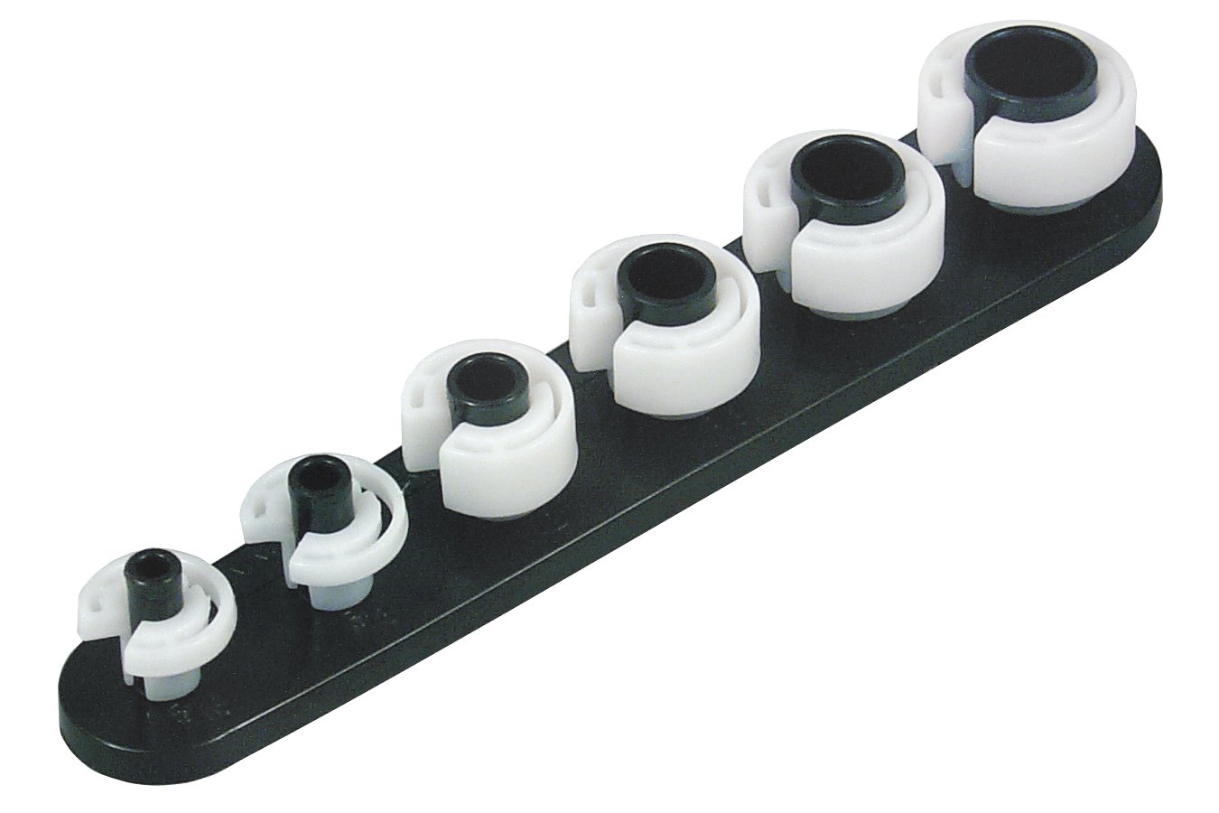
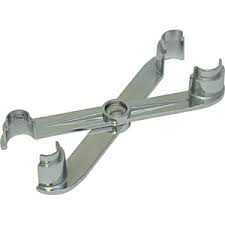
1.) Separate the pressure line (the one with the Schrader valve on it) using the fuel line tools.
Look in the A/C repair section for the fuel line tools. They look like little plastic top hats. You will need the 1/2" & 5/8" ones. The hat shaped section goes on facing the large part of the coupling. Then you press hard on the brim until it forces the sleeve into the coupling and releases the spring. You may need someone to pull on the line while you press on the coupling.
OR
View: https://www.youtube.com/watch?v=vRTjYAxvaCs
Use a piece of garden hose to run from the pressure line to your bucket or gas can. Make sure it is as leak proof as you can make it. Fire and explosion are not part of the repair process...
2.) Jumper the fuel pump test point to ground.

Turn the ignition switch to the Run position. the fuel pump will pump the tank almost dry unless the battery runs down first.
Some 5 gallon paint pails lined with garbage bags are good to hold the gas. The garbage bags provide a clean liner for the pails and keep the loose trash out of the gas so you can reuse it. If you decide to use a siphon, a piece of 1/2" garden hose stuck down the filler neck will siphon all but a gallon or so of the gas.
Remove the filler neck bolts and put them in a zip bag. Disconnect the supply & return lines by removing the plastic clips from the metal tubing. If you damage the clips, you can get new ones form the auto part store for just a few dollars. I have used tie-wraps, but that is not the best choice. Then you remove the two 9/16" nuts that hold the T bolts to the straps. Put the nuts in the zip bag with the filler bolts. Pull the plastic shield down and away from the tank. Once the tank drops a little bit you can disconnect the wiring for the pump & fuel quantity sender.
The fuel gauge sender assembly comes out by removing a large metal ring that unscrews from the tank. There is a separate mounting/access plate for the fuel pump and fuel gage. You are supposed to use a brass punch to tap on the ring so that you don't make sparks. Look closely at the rubber O ring gasket when you remove the fuel gauge sender.
When you install the metal ring that holds the sender in place, watch out for the gasket O ring. Some RTV may be helpful if the ring is not in excellent condition.
The tank to filler pipe seal is a large rubber grommet. Inspect it for hardening, tears and damage. At $20 from the Ford dealer, it might be a good idea to replace it.
I used a floor jack to help lift the tank back in place. You may find that it is the only time you really can make good use of a helper.
All resistance measurements should be made with the power off.
Note from bstrd86 - 86 and older fuel tank sender units are 73 ohms empty, 8-12 ohms full.
The yellow/white wire will show a voltage that varies with the movement of the float on the sender unit. To test the sender, set your Ohmmeter or DVM on low Ohms. Then disconnect the sender and connect the Ohmmeter or DVM to the yellow/white and black wires from the sender unit. Move the float arm while watching the Ohmmeter or DVM. You should see the reading change from 22 to 145 ohms +/- 10%.
If the Ohmmeter or DVM resistance readings are way off, replace the tank sender unit.
Use extreme caution if you do the next step. Fumes from the gas tank can easily ignite and cause a fire or explosion.
With the sender unit out of the tank and connected to the body wiring harness, turn the ignition switch to the Run position. Move the float arm and the fuel gauge indicator should move. If you are very careful, you can use a pair of safety pins inserted in the connector for the yellow/white and black wires to measure the voltage as you move the float arm. The voltage will change, but I have no specs for what it should be.
Do not short the safety pins together or to ground. If you do, you may damage the anti-slosh module or crate a spark. A spark with the fuel tank open could cause a fire or an explosion.
If the voltage does not change and the tanks sender passed the resistance tests, the anti-slosh module or gauge is bad.
Anti-Slosh module pictures courtesy of Saleen0679

Copied from DrBob
I worked on an 88 Mustang today that had similar symptoms. Short version, I took the “anti slosh module” off of the back of the instrument cluster and replaced the electrolytic capacitor. Fixed it for $1.39 with a part from Radio Shack.
In an attempt to help other folks, here’s the long version.
Remove the “anti slosh module” located on the back of the instrument cluster. There was a single Torx screw holding mine to the cluster.
Find the electrolytic capacitor. It will be the largest, 2 wire component on the board. The capacitor may have a red or blue plastic wrapper on it. Mine was red.
The wrapper should have printing on it. Look for printing that looks something like this:
100uF+25V
The “100uF” tells you this is a 100 micro Farad capacitor. The “+25V” tells you the capacitor is rated for 25 Volts. Yours may be different. You may use a higher voltage part but don't use a lower rated voltage part. If you use a lower voltage part the capacitor might open later on down the road or it could be as bad as catching fire.
If you can’t find the printing you’ll need to remove the part. You have to anyway so nothing wasted. However pay close attention to the way the capacitor is oriented on the board.
One end of the capacitor will be bare metal with a wire sticking out. The other end should have some sort of insulation over it with a wire sticking out. The bare metal end is the negative end while the insulated end is the positive end. Pay attention to which end is connected to which hole on the board.
Get a replacement part. I got mine at Radio Shack, $1.39. Here’s the info:
100µF 35V 20% Axial-Lead Electrolytic Capacitor
Model: 272-1016 | Catalog #: 272-1016
Fuel tank sender unit:
http://www.latemodelrestoration.com/products/Mustang-Gas-And-Fuel-Tank-Sending-Unit
Be sure to get the lock ring and a new seal if you order the tank sender unit.
http://www.latemodelrestoration.com...ng-Fuel-Pump-Sending-Unit-Lock-Ring-And-Seal\
Turn signal problems
If the external lights blink when you operate the turn signal with the ignition switch in the Run position, don't worry about not hearing the blinker sound.
If the external lights blink OK but the dash lights don't, you either have a bad connection or both indicator bulbs are burned out
See http://www.stangnet.com/tech/cluster87-93.pdf for information on the wiring for the instrument cluster.
You will need the Adobe Acrobat viewer which is also a free download – http://get.adobe.com/reader/
If that does not resolve your problem with the turn signals, see below...
87-90 Mustang Turn signal troubleshooting
The ignition switch is also known for creating turn signal problems. Make sure the ignition switch and wiring are in good shape as a first item to check. This is especially true if you are having problems with things like the radio and heater/AC blower.
Ignition switch wiring

Some of the symptoms of ignition switch problems are things that don’t work or are intermittent like radio, turn signals, wipers or heater. The auto parts stores sell the switches for $13-$15.


While you are working on the switch, check the wiring and connector closely. A replacement connector with new wiring pigtails is available from most auto parts stores
AutoZone and Advanced Auto Parts have the same Part Number: 434 - may have to order, not always in stock
Advanced Auto Parts alternate part number: PT5534

If just the plastic shell is broken, a small jeweler’s screwdriver inserted from the front will release the contacts from the connector shell. Do this one wire at time and insert the wire and connector you removed into the same position on the replacement connector shell.
Saleen0679 was nice enough to dig this up for us awhile back: Replace a 1979-1993 Ignition Switch Assembly
Torx bit set from Advance Auto Parts

Autocraft torx bit set – have small hole in tip for tamper proof screws.
Part No. AC571/W1386 Cost approx. $12 +tax
Turn Signal Troubleshooting
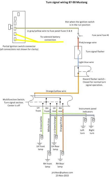
Keep in mind that the flasher on the front of the fuse panel is for the hazard flasher. Locate the turn signal flasher, depending on the model year it may be behind the radio or on the backside of the fuse panel or behind the glove compartment.
Turn the ignition switch to Run; the engine does not need to be running for these tests. With the turn signal flasher removed, test the pink/orange wire for 12 volts.
Set the voltmeter to DC volts and select the scale that is closest to 12 volts. Clip one voltmeter probe on the bare metal part of the car body for a ground and put the other probe in the turn signal flasher socket contact that has the pink/orange wire. You should see about 12 volts.
No 12 volts present: replace the fuse and check for 12 volts again as described above. Do not turn the ignition switch off if you are testing for voltage.
Still no 12 volts, pull the fuse and test the #5 fuse socket contacts for 12 volts. One contact will have 12 volts. One probe is grounded, the other probe gets stuck in the fuse contacts. Test both contacts for 12 volts.
No 12 volts on either fuse contact, the ignition switch or ignition switch wiring is suspect. Move things around so that you can get to the backside of the ignition switch wiring connector with the ignition switch still connected to it. Make sure that you don't turn the ignition switch OFF while you are testing it. It still needs to be in the Run position. Look for 12 volts on the large gray/yellow wire. No 12 volts and you have a bad ignition switch or some bad wiring. Wiggle the large gray/yellow wire to see if it gets or loses voltage while you are checking it.
Diagrams courtesy of Tmoss & Stang&2birds
Fuse box layout
Ignition switch wiring
Once you have located the turn signal flasher, remove it from its socket and jumper the socket contacts together. Turn the ignition switch to Run and try both left and right turn signals. They should come on steady if you have good 12 volts to the pink/orange wire. If the lights turn on steady and bright, that means the flasher is suspect. If you find one more bulbs do not come on steady and bright, then you have either a bad bulb, bad ground at the bulb socket or a corroded or bad socket.
If you still have problems, then it is the multifunction switch, or its wiring; that is a case of last resort.
Multifunction turn signal switch:
Before you think about replacing the multifunction switch with one from the junkyard, here are some things to be aware of...
The problem is more common in GT models because they had fog lights on the same power wiring as the headlights. Ford undersized the wire and that caused problems.
A word of caution about multifunction switches is in order here. The multifunction switch (high/low beam, wiper, turn signals) are different for different years. 87-98 will work in any 87-89 car. The 90-93 switches only work in 90-93 cars. You can't put an early model switch in a late model car, nor can you put a late model switch in an early car.
Supposedly you can move the pins around to make the switches work in model years that are different from the car the switch came out of. I cannot verify that and haven’t tried it.
Other possible problem sources for the turn signal & headlight malfunction are the ignition switch, multifunction switch and the plastic shell that holds the turn signal wiring connector pins.
The following diagram is for 87-89 model cars.
Turn signal switch wiring:

The following diagram is for 90-93model cars.
Turn signal switch wiring:

Drive gear location on the transmission:
Speedometer cable replacement for 87-93 Mustangs
Revised 11 Mar-2015 to add tip on what to look for when there is a bouncing speedometer.
How the speedometer works:
The indicator pointer has no direct connection to the speedo cable. It uses a drum with magnets on it to couple to the pointer. The drum turns and tries to twist the circular steel disk that is mounted on the pointer spindle. The magnetic force is all that connects the drum to the circular disk. There is very little clearance between the disk and drum, only a few thousands of an inch.
Lubrication warning
Use a graphite based lubricant for the speedo cable. It is available at most auto parts stores in a very small tube. Lubricate only the lower half of the cable. The reason for this is that if you use too much lubricant, it works its way up into the speedo head and gets between the rotating magnet and the disk. This causes the speedo to seize up and may wring the indicator needle off the indicator spindle. You may be able to fix things up with non-flammable brake parts cleaner to clean the disk and magnet assembly. Count on replacing the current cable and housing with a new cable and housing. You need to do this to prevent the excess lubricant from causing it to fail again.
A speedometer that bounces around is either a cable problem (top cause) or a speedometer drive gear that is chewed up. When you remove the cable drive end, check the teeth on the driven gear (the one attached to the cable) or the drive gear (the one on the transmission output shaft) Late Model Restoration (http://www.latemodelrestoration.com/products/79-93-Mustang-Transmission-Speedometer-Correction) has a complete range of replacement speedometer gear sets.
Speedometer cable replacement .
Note: All 89-93 cars have a VSS sensor even if they do not have cruise control. The 87-88 only have a VSS sensor if they have cruise control.
Speedo cable housing assembly without cruise control:
The VSS equipped cars have a speedo cable with a different fitting on the transmission end of the cable. It is the fitting on the LH side of the following picture.
Speedo cable housing assembly with cruise control
Preparation: if you are only going to replace the inner part of the speedo cable, get lots of newspaper or a painter’s drop cloth to cover the inside front of the car. About the time you have the dirty, oily speedo cable core all over your lap and the inside of the car, you will thank me for this suggestion.
Replacing only the inner cable: see steps 1- 6, 12, 13, 17-21
Replacing the housing and inner cable as an assembly: see steps 1-11, 13-21
Inside the car:
1.) Remove the shield around the steering column that covers the ignition switch & turn indicator switch.
2.) You now have access to the two screws that hold the lower part of the cluster housing in place. Remove them and place them in a zip bag.
3.) Use a stubby or an offset Philips screwdriver to remove the two screws on the top of the cluster housing. The screws are up close to the windshield, so they can be hard to get at.
4.) The cluster housing will now slide forward: depending on your particular car, you may or may not have to disconnect the wiring for the headlights, hazard lights, or cluster wiring. All of the wiring uses plastic connectors with plastic spring clips on them. To release the connectors, lift the plastic clips and pull straight back.
5.) The speedo cable is secured in the speedo head by a white plastic clip. Depress the clip or squeeze it and pull the cable out of the speedo head. This can be tricky, but it will come out if you have the white clip depressed enough.
Speedo head cable clip
Photos courtesy of Almost Stock
6.) With speedo cable removed from the speedo head, try twisting the cable end with your fingers. If it turns more than 1/4 turn, the cable may either be broken or you have damage at the other end where the cable mates to the VSS sensor or speedo pickup gear in the transmission.
Outside the car, replacing the cable housing assembly.
The following steps are necessary only if you plan on replacing the cable & cable housing assembly.
7.) If you are going to the replace the cable housing, the next step is important. Tie a study string or wire to the VSS sensor end of the cable housing. This string or wire is to be used to fish the cable housing back through the maze of wires that is under the dash. If all you are going to do is replace the inner cable, you can omit this step.
8.) Jack up the car, all 4 tires must be off the ground. Place jackstands under the car for safety.
9.) Locate the VSS sensor on the driver’s side of the transmission tailshaft housing. The speedo cable housing will be secured in the VSS sensor with a hairpin clip Do not remove the clip!!!: The hairpin clip stays in place. If you remove it, the odds are that you will not be able to get the cable to stay in place on re-installation. Pull firmly straight back on the cable housing and it will come out. A considerable amount of effort may be required to get the cable out of the VSS sensor, but it will pull out.
10.) Release the cable housing from the clips that secure it to the car body.
Inside the car:
11.) If all you are going to do is replace the inner cable, you can omit this step.
The housing assembly can then be pulled out and the fish string or wire can be removed from the old cable housing and secured to the new one.
12.) You can omit this step if you are replacing the cable & cable housing assembly.
The inner cable can be removed by pulling it out of the housing assembly. Watch out for the lubricant so that you don’t get it on the car’s interior.
13.) You can omit this step if you are replacing the cable & cable housing assembly.
Lubricate only the lower part of the new cable with speedometer lubricant or graphite. Don’t use too much lubricant, or it will work its way up into the speedo head unit and damage it. Thread the inner cable into the housing, turning it as you go. When you are all the way in with the new cable, it will engage the VSS sensor and stop turning.
Outside the car, replacing the cable housing assembly.
The following steps are necessary only if you plan on replacing the cable & cable housing assembly.
14.) Use the fish string or wire to feed the cable housing assembly through the dash wiring and out the cable hole in the firewall.
15.) Secure the cable in the body clips, making sure that the cable isn’t rubbing against the exhaust pipe.
16.) Push the cable housing assembly into the VSS sensor until it snaps in past the hairpin clip. Connect VSS wiring connector back to VSS sensor.
Inside the car:
17.) Push the cable housing back into the speedo head unit. You should be able to feel the white clip click into place.
18.) Reconnect all the wires & connectors on the speedo head unit.
19.) Re-install the cluster unit in the dash & tighten the 4 screws that hold it in place.
20.) Re-install the cover for the ignition switch & turn signal.
21.) If the car is up on jackstands, start the car, place it in gear & watch the speedo to see if it works OK. If you didn’t jack the car up, take a test drive.
The red/yellow wire (power supply to gauge & sender) should have 12 volts when the ignition is in the start or Run position.
Troubleshooting the gauge and sender circuit:
Since the sender uses a variable resistor, sum the resistor values of 22 Ohms (empty value) & 145 Ohms (full value). That gets you 167, which you divide by 2: that gets you 83.5. So in theory, 83.5 ohms is 1/2 full. A trip to Radio Shack for the closest combination of resistors to make 83.5 ohms gets you one 68 Ohm (Catalog #: 271-1106) + one 15 Ohm (Catalog #: 271-1102) for a total of 83 Ohms at the cost of $2 plus tax. Wire the resistors in series to make a resistor pack and cover it with heat shrink tubing or electrical tape. The 83 Ohms is close enough to the 83.5 Ohm figure that it shouldn't matter. Disconnect the electrical connector shown in your for the tank sender unit. Connect one end of the resistor pack to the yellow/white wire on the body side fuel sender electrical connector and the other end of the resistor pack to ground. Make sure nothing is touching that isn't supposed to and turn the ignition switch to Run. If I am correct, the fuel gauge will read 1/2 full, or very close to it. If it does not, then the odds are that the gauge or anti-slosh unit are bad.
How and why the test works…
Most of the fuel gauge failures give a stuck on full or stuck on empty as a problem symptom. Using a resistor combination that mimics 1/2 tank allows you to decide if the gauge and anti-slosh module are the problem source.
If the gauge reads about 1/2 tank with the resistor combination, that points to the sender as being the culprit.
If the gauge reads full or empty with the resistor pack in place of the sender, then the gauge or anti-slosh module is at fault.
Fuel gauge sender testing and replacement
The next steps require dropping the fuel tank and removal of the fuel level sender. Here are some useful tips...
I have done the tank removal three times, and the main issues are getting the car up on jack stands and getting the gas out of the tank. DO NOT try to do this job without jack stands. Becoming a pancake is not part of the repair process.
Pumping out the old gas:
If the old pump still works, you can use it to pump the tank out.
1.) Separate the pressure line (the one with the Schrader valve on it) using the fuel line tools.
Look in the A/C repair section for the fuel line tools. They look like little plastic top hats. You will need the 1/2" & 5/8" ones. The hat shaped section goes on facing the large part of the coupling. Then you press hard on the brim until it forces the sleeve into the coupling and releases the spring. You may need someone to pull on the line while you press on the coupling.
OR
View: https://www.youtube.com/watch?v=vRTjYAxvaCs
Use a piece of garden hose to run from the pressure line to your bucket or gas can. Make sure it is as leak proof as you can make it. Fire and explosion are not part of the repair process...
2.) Jumper the fuel pump test point to ground.
Turn the ignition switch to the Run position. the fuel pump will pump the tank almost dry unless the battery runs down first.
Some 5 gallon paint pails lined with garbage bags are good to hold the gas. The garbage bags provide a clean liner for the pails and keep the loose trash out of the gas so you can reuse it. If you decide to use a siphon, a piece of 1/2" garden hose stuck down the filler neck will siphon all but a gallon or so of the gas.
Remove the filler neck bolts and put them in a zip bag. Disconnect the supply & return lines by removing the plastic clips from the metal tubing. If you damage the clips, you can get new ones form the auto part store for just a few dollars. I have used tie-wraps, but that is not the best choice. Then you remove the two 9/16" nuts that hold the T bolts to the straps. Put the nuts in the zip bag with the filler bolts. Pull the plastic shield down and away from the tank. Once the tank drops a little bit you can disconnect the wiring for the pump & fuel quantity sender.
The fuel gauge sender assembly comes out by removing a large metal ring that unscrews from the tank. There is a separate mounting/access plate for the fuel pump and fuel gage. You are supposed to use a brass punch to tap on the ring so that you don't make sparks. Look closely at the rubber O ring gasket when you remove the fuel gauge sender.
When you install the metal ring that holds the sender in place, watch out for the gasket O ring. Some RTV may be helpful if the ring is not in excellent condition.
The tank to filler pipe seal is a large rubber grommet. Inspect it for hardening, tears and damage. At $20 from the Ford dealer, it might be a good idea to replace it.
I used a floor jack to help lift the tank back in place. You may find that it is the only time you really can make good use of a helper.
All resistance measurements should be made with the power off.
Note from bstrd86 - 86 and older fuel tank sender units are 73 ohms empty, 8-12 ohms full.
The yellow/white wire will show a voltage that varies with the movement of the float on the sender unit. To test the sender, set your Ohmmeter or DVM on low Ohms. Then disconnect the sender and connect the Ohmmeter or DVM to the yellow/white and black wires from the sender unit. Move the float arm while watching the Ohmmeter or DVM. You should see the reading change from 22 to 145 ohms +/- 10%.
If the Ohmmeter or DVM resistance readings are way off, replace the tank sender unit.
Use extreme caution if you do the next step. Fumes from the gas tank can easily ignite and cause a fire or explosion.
With the sender unit out of the tank and connected to the body wiring harness, turn the ignition switch to the Run position. Move the float arm and the fuel gauge indicator should move. If you are very careful, you can use a pair of safety pins inserted in the connector for the yellow/white and black wires to measure the voltage as you move the float arm. The voltage will change, but I have no specs for what it should be.
Do not short the safety pins together or to ground. If you do, you may damage the anti-slosh module or crate a spark. A spark with the fuel tank open could cause a fire or an explosion.
If the voltage does not change and the tanks sender passed the resistance tests, the anti-slosh module or gauge is bad.
Anti-Slosh module pictures courtesy of Saleen0679
Copied from DrBob
I worked on an 88 Mustang today that had similar symptoms. Short version, I took the “anti slosh module” off of the back of the instrument cluster and replaced the electrolytic capacitor. Fixed it for $1.39 with a part from Radio Shack.
In an attempt to help other folks, here’s the long version.
Remove the “anti slosh module” located on the back of the instrument cluster. There was a single Torx screw holding mine to the cluster.
Find the electrolytic capacitor. It will be the largest, 2 wire component on the board. The capacitor may have a red or blue plastic wrapper on it. Mine was red.
The wrapper should have printing on it. Look for printing that looks something like this:
100uF+25V
The “100uF” tells you this is a 100 micro Farad capacitor. The “+25V” tells you the capacitor is rated for 25 Volts. Yours may be different. You may use a higher voltage part but don't use a lower rated voltage part. If you use a lower voltage part the capacitor might open later on down the road or it could be as bad as catching fire.
If you can’t find the printing you’ll need to remove the part. You have to anyway so nothing wasted. However pay close attention to the way the capacitor is oriented on the board.
One end of the capacitor will be bare metal with a wire sticking out. The other end should have some sort of insulation over it with a wire sticking out. The bare metal end is the negative end while the insulated end is the positive end. Pay attention to which end is connected to which hole on the board.
Get a replacement part. I got mine at Radio Shack, $1.39. Here’s the info:
100µF 35V 20% Axial-Lead Electrolytic Capacitor
Model: 272-1016 | Catalog #: 272-1016
Fuel tank sender unit:
http://www.latemodelrestoration.com/products/Mustang-Gas-And-Fuel-Tank-Sending-Unit
Be sure to get the lock ring and a new seal if you order the tank sender unit.
http://www.latemodelrestoration.com...ng-Fuel-Pump-Sending-Unit-Lock-Ring-And-Seal\
Turn signal problems
If the external lights blink when you operate the turn signal with the ignition switch in the Run position, don't worry about not hearing the blinker sound.
If the external lights blink OK but the dash lights don't, you either have a bad connection or both indicator bulbs are burned out
See http://www.stangnet.com/tech/cluster87-93.pdf for information on the wiring for the instrument cluster.
You will need the Adobe Acrobat viewer which is also a free download – http://get.adobe.com/reader/
If that does not resolve your problem with the turn signals, see below...
87-90 Mustang Turn signal troubleshooting
The ignition switch is also known for creating turn signal problems. Make sure the ignition switch and wiring are in good shape as a first item to check. This is especially true if you are having problems with things like the radio and heater/AC blower.
Ignition switch wiring
Some of the symptoms of ignition switch problems are things that don’t work or are intermittent like radio, turn signals, wipers or heater. The auto parts stores sell the switches for $13-$15.
While you are working on the switch, check the wiring and connector closely. A replacement connector with new wiring pigtails is available from most auto parts stores
AutoZone and Advanced Auto Parts have the same Part Number: 434 - may have to order, not always in stock
Advanced Auto Parts alternate part number: PT5534
If just the plastic shell is broken, a small jeweler’s screwdriver inserted from the front will release the contacts from the connector shell. Do this one wire at time and insert the wire and connector you removed into the same position on the replacement connector shell.
Saleen0679 was nice enough to dig this up for us awhile back: Replace a 1979-1993 Ignition Switch Assembly
Torx bit set from Advance Auto Parts
Autocraft torx bit set – have small hole in tip for tamper proof screws.
Part No. AC571/W1386 Cost approx. $12 +tax
Turn Signal Troubleshooting
Keep in mind that the flasher on the front of the fuse panel is for the hazard flasher. Locate the turn signal flasher, depending on the model year it may be behind the radio or on the backside of the fuse panel or behind the glove compartment.
Turn the ignition switch to Run; the engine does not need to be running for these tests. With the turn signal flasher removed, test the pink/orange wire for 12 volts.
Set the voltmeter to DC volts and select the scale that is closest to 12 volts. Clip one voltmeter probe on the bare metal part of the car body for a ground and put the other probe in the turn signal flasher socket contact that has the pink/orange wire. You should see about 12 volts.
No 12 volts present: replace the fuse and check for 12 volts again as described above. Do not turn the ignition switch off if you are testing for voltage.
Still no 12 volts, pull the fuse and test the #5 fuse socket contacts for 12 volts. One contact will have 12 volts. One probe is grounded, the other probe gets stuck in the fuse contacts. Test both contacts for 12 volts.
No 12 volts on either fuse contact, the ignition switch or ignition switch wiring is suspect. Move things around so that you can get to the backside of the ignition switch wiring connector with the ignition switch still connected to it. Make sure that you don't turn the ignition switch OFF while you are testing it. It still needs to be in the Run position. Look for 12 volts on the large gray/yellow wire. No 12 volts and you have a bad ignition switch or some bad wiring. Wiggle the large gray/yellow wire to see if it gets or loses voltage while you are checking it.
Diagrams courtesy of Tmoss & Stang&2birds
Fuse box layout
Ignition switch wiring
Once you have located the turn signal flasher, remove it from its socket and jumper the socket contacts together. Turn the ignition switch to Run and try both left and right turn signals. They should come on steady if you have good 12 volts to the pink/orange wire. If the lights turn on steady and bright, that means the flasher is suspect. If you find one more bulbs do not come on steady and bright, then you have either a bad bulb, bad ground at the bulb socket or a corroded or bad socket.
If you still have problems, then it is the multifunction switch, or its wiring; that is a case of last resort.
Multifunction turn signal switch:
Before you think about replacing the multifunction switch with one from the junkyard, here are some things to be aware of...
The problem is more common in GT models because they had fog lights on the same power wiring as the headlights. Ford undersized the wire and that caused problems.
A word of caution about multifunction switches is in order here. The multifunction switch (high/low beam, wiper, turn signals) are different for different years. 87-98 will work in any 87-89 car. The 90-93 switches only work in 90-93 cars. You can't put an early model switch in a late model car, nor can you put a late model switch in an early car.
Supposedly you can move the pins around to make the switches work in model years that are different from the car the switch came out of. I cannot verify that and haven’t tried it.
Other possible problem sources for the turn signal & headlight malfunction are the ignition switch, multifunction switch and the plastic shell that holds the turn signal wiring connector pins.
The following diagram is for 87-89 model cars.
Turn signal switch wiring:
The following diagram is for 90-93model cars.
Turn signal switch wiring:
Last edited:
Similar threads
- Replies
- 4
- Views
- 574
- Replies
- 2
- Views
- 267
- Replies
- 2
- Views
- 251
- Replies
- 5
- Views
- 830
- Replies
- 11
- Views
- 740