@Bradyroberts
The information you need is in the tech notes below...
Fuel Pump Troubleshooting for 91-93 Mustangs
Revised 6-Feb-2016 to add fuse link diagram
Ignition switch in the Run position, engine not running tests.
Clue – listen for the fuel pump to prime when you first turn the ignition switch on.
It should run for 2-5 seconds and shut off. To trick the fuel pump into running, find the ECC test connector and jump the connector in the upper RH corner to ground.
Foxbody Diagnostic connector
Foxbody Diagnostic connector close up view
If the fuse links are OK, you will have power to the pump. Check fuel pressure – remove the cap from the Schrader valve behind the alternator and depress the core. Fuel should squirt out, catch it in a rag. A tire pressure gauge can also be used if you have one - look for 37-40 PSI. Beware of fire hazard when you do this.
No fuel pressure, possible failed items in order of their probability:
A.) Tripped inertia switch – press reset button on the inertia switch. The hatch cars hide it under the plastic trim covering the driver's side taillight. Use the voltmeter or test light to make sure you have power to both sides of the switch
B.) Fuel pump Relay:
On 91 cars, it is located under the driver's seat.
On 92 and 93 cars it is located under the MAF. Be careful not to confuse it with the A/C WOT cutoff relay which is in the same area. See the diagram to help identify the fuel pump relay wiring colors.
Be sure to closely check the condition of the relay, wiring & socket for corrosion and damage.
C.) Clogged fuel filter
D.) Failed fuel pump
E.) Blown fuse link in wiring harness.
F.) Fuel pressure regulator failed. Remove vacuum line from regulator and inspect
for fuel escaping while pump is running.
Theory of operation:
Read this section through several times. If you understand the theory of operation, this will be much easier to troubleshoot. Refer to the diagram below frequently.
Diagram of the fuel pump wiring for 91-93 cars.
The electrical circuit for the fuel pump has two paths, a control path and a power
path.
Remember that the computer does not source any power to actuators, relays or injectors, but provides the ground necessary to complete the circuit. That means one side of the circuit will always be hot, and the other side will go to ground or below 1 volt as the computer switches on that circuit.
Control Path
The control path consists of the computer, and the fuel pump relay coil. It turns the fuel pump relay on or off under computer control. The switched power (red wire) from the ECC relay goes to the relay coil and then from the relay coil to the computer (light blue\orange wire). The computer provides the ground path to complete the circuit. This ground causes the relay coil to energize and close the contacts for the power path. Keep in mind that you can have voltage to all the right places, but the computer must provide a ground. If there is no ground, the relay will not close the power contacts.
Computer power path
The computer power relay must properly function to provide power for the fuel pump relay. That means you must check the operation of the computer power relay (PCM Power Relay) before chasing any problems with the fuel pump circuit. The computer power relay is located above the computer under the passenger side kick plate cover. . It is not easy to get to, you must have small hands or pull the passenger side dash speaker out to access it.
With the Ignition switch in the Off position, check the resistance between the black/white wire and a clean bare spot on the car body metal. You should see less that 1 Ohm. More than 1 Ohm is a broken wire, or bad connection of the black/white wire and the car body metal.
Check for 12 volts at the yellow wire. Good 12 volts and the fuse link is OK. No voltage or low voltage, bad fuse link, bad wiring, or connections.
With the Ignition switch in the Run position, look for good 12 volts on the red/green wire. No voltage or low voltage, bad fuse link, bad wiring, or connections.
Good 12 volts on the red/green wire, look for good 12 volts on the red wire or any of the red fuel injector wires. No 12 volts or low voltage and the relay isn’t closing, or relay socket contacts are dirty/corroded. Water has been known to run down the radio antenna wire or leak from the windshield and get into the relay and relay contacts.
Fuel pump power path
The power path picks up from a fuse link near the starter relay. Fuse links are like fuses, except they are pieces of wire and are made right into the wiring harness. The feed wire from the fuse link (pink/black wire) goes to the fuel pump relay contacts. When the contacts close because the relay energizes, the power flows through the pink/black wire to the contacts and through the dark green\yellow wire to the inertia switch. The other side of the inertia switch with the brown\pink wire joins the pink/black wire that connects to the fuel pump. The fuel pump has a black wire that supplies the ground to complete the circuit.
Fuse links at starter solenoid
Fuse links come with a current rating just like fuses. A clue as to what current they are designed for is to look at the size wire they protect.
Fuse link material is available at most good auto parts stores. There may even be a fuse link already made up specifically for your car. Just be sure to solder the connection and cover it with heat shrink tubing.
Heat shrink tubing is available at Radio Shack or other electronics supply stores.
See the video below for help on soldering and heat shrinking wiring. There is a lot of useful help and hints if you don’t do automotive electrical work all the time.
View: http://youtu.be/uaYdCRjDr4A
Power feed: Look for 12 volts at the pink/black wire (power source for fuel pump relay).
No voltage or low voltage, bad fuse link, bad wiring, or connections. Remember that on 92 or later models the fuel pump relay is located under the Mass Air meter. Watch out for the WOT A/C control relay on these cars, as it is located in the same place and can easily be mistaken for the fuel pump relay.
Relay: Turn on the key and jumper the ECC test connector as previously described. Look for 12 volts at the dark green\yellow wire (relay controlled power for the fuel pump). No voltage there means that the relay has failed, or there is a broken wire in the relay control circuit.
Inertia switch:
The location for the inertia switch is under the plastic for the driver's side taillight.
There should be a round plastic pop out cover over it, remove it to access the switch button.
With the test connection jumpered and ignition switch in The Run position as described above, check the brown/pink wire. It should have 12 volts. No 12 volts there, either the inertia switch is open or has no power to it. Check both sides of the inertia switch: there should be power on the dark green\yellow (inertia switch input) and brown/pink wire (inertia switch output). Power on the dark green\yellow wire and not on the brown/pink wire means the inertia switch is open.
Press on the red plunger to reset it to the closed position. Sometimes the inertia switch will be intermittent or will not pass full power. Be sure that there is 12 volts on both sides of the switch with the pump running and that the voltage drop measured across the switch is less than .75 volts.
Pump wiring: Anytime the ignition switch is in the Run position and the test point is jumpered to ground, there should be at least 12 volts present on the black/pink wire. With power off, check the pump ground: you should see less than 1 ohm between the black wire and chassis ground.
Make sure that the power is off the circuit before making any resistance checks.
If the circuit is powered up, your resistance measurements will be inaccurate.
Control path:
Relay: The light blue/orange wire provides a ground path for the relay power. With the test connector jumpered according to the previous instructions, there should be less than .75 volts.
Use a test lamp with one side connected to battery power and the other side to the light blue/orange wire on the fuel pump relay. The test light should glow brightly. No glow and you have a broken wire or bad connection between the test connector and the relay. To test the wiring from the computer, remove the passenger side kick panel and disconnect the computer connector. It has a 10 MM bolt that holds it in place. Remove the test jumper from the ECC test connector.
With the test lamp connected to power, jumper pin 22 to ground and the test lamp should glow.
No glow and the wiring between the computer and the fuel pump relay is bad.
Computer: If you got this far and everything else checked out good, the computer is suspect.
Remove the test jumper from the ECC test connector located under the hood. Probe computer pin 22 with a safety pin and ground it to chassis. Make sure the computer and everything else is connected. Turn the ignition switch to the Run position and observe the fuel pressure. The pump should run at full pressure.
If it doesn't, the wiring between pin 22 on the computer and the fuel pump relay is bad.
If it does run at full pressure, the computer may have failed.
Keep in mind that the computer only runs the fuel pump for about 2-3 seconds when you turn the key to the Run position. This can sometimes fool you into thinking the computer has died.
Connect one lead of the test light to power and the other lead to computer pin 22 with a safety pin.
With the ignition switch Off, jumper the computer into self test mode like you are going to dump the codes. Turn the ignition switch to the Run position. The light will flicker when the computer does the self test routine. A flickering light is a good computer. No flickering light is a bad computer. Remove the test jumper from the ECC test connector located under the hood.
See the following website for some help from Tmoss (diagram designer) & Stang&2Birds (website host)
for help on 88-95 wiring
Mustang FAQ - Engine Information
Fuel pump runs continuously:
The fuel pump relay contacts are stuck together or the light blue/orange wire (pin 22) has shorted to ground. Remove the fuel pump relay from its socket. Then disconnect the computer and use an ohmmeter to check out the resistance between the light blue/orange wire and ground. You should see more than 10 K Ohms (10,000 ohms) or an infinite open circuit. Be sure that the test connector isn’t jumpered to ground.
If the wiring checks out good, then the computer is the likely culprit.
Prior to replacing the computer, check the computer power ground. The computer has its own dedicated power ground that comes off the ground pigtail on the battery ground wire. Due to it's proximity to the battery, it may become corroded by acid fumes from the battery. It is a black cylinder about 2 1/2" long by 1" diameter with a black/lt green wire. You'll find it up next to the starter solenoid where the wire goes into the wiring harness.
The picture shows the common ground point for the battery , computer, & extra 3G alternator ground wire as described above. A screwdriver points to the bolt that is the common ground point.
The battery common ground is a 10 gauge pigtail with the computer ground attached to it.
Picture courtesy timewarped1972
Fuel Quantity gauge troubleshooting 87-93 Mustangs
Revised 8-Apr-2017 to add warning about non-interchangeable fuel tank senders between 86 -79 and 97 -93 Mustangs.
The red/yellow wire (power supply to gauge & sender) should have 12 volts when the ignition is in the start or Run position.
Troubleshooting the gauge and sender circuit:
Since the sender uses a variable resistor, sum the resistor values of 22 Ohms (empty value) & 145 Ohms (full value). That gets you 167, which you divide by 2: that gets you 83.5. So in theory, 83.5 ohms is 1/2 full. A trip to Radio Shack for the closest combination of resistors to make 83.5 ohms gets you one 68 Ohm (Catalog #: 271-1106) + one 15 Ohm (Catalog #: 271-1102) for a total of 83 Ohms at the cost of $2 plus tax. Wire the resistors in series to make a resistor pack and cover it with heat shrink tubing or electrical tape. The 83 Ohms is close enough to the 83.5 Ohm figure that it shouldn't matter. Disconnect the electrical connector shown in the diagram for the tank sender unit. Connect one end of the resistor pack to the yellow/white wire on the body side fuel sender electrical connector and the other end of the resistor pack to ground. Make sure nothing is touching that isn't supposed to and turn the ignition switch to Run. If I am correct, the fuel gauge will read 1/2 full, or very close to it. If it does not, then the odds are that the gauge or anti-slosh unit are bad.
How and why the test works…
Most of the fuel gauge failures give a stuck on full or stuck on empty as a problem symptom. Using a resistor combination that mimics 1/2 tank allows you to decide if the gauge and anti-slosh module are the problem source.
If the gauge reads about 1/2 tank with the resistor combination, that points to the sender as being the culprit.
If the gauge reads full or empty with the resistor pack in place of the sender, then the gauge or anti-slosh module is at fault.
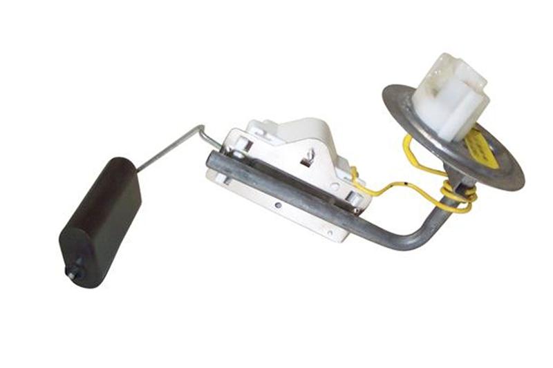
Fuel gauge sender testing and replacement
The next steps require dropping the fuel tank and removal of the fuel level sender. Here are some useful tips...
I have done the tank removal three times, and the main issues are getting the car up on jack stands and getting the gas out of the tank. DO NOT try to do this job without jack stands. Becoming a pancake is not part of the repair process.
Pumping out the old gas:
If the old pump still works, you can use it to pump the tank out.
1.) Separate the pressure line (the one with the Schrader valve on it) using the fuel line tools.
Look in the A/C repair section for the fuel line tools. They look like little plastic top hats. You will need the 1/2" & 5/8" ones. The hat shaped section goes on facing the large part of the coupling. Then you press hard on the brim until it forces the sleeve into the coupling and releases the spring. You may need someone to pull on the line while you press on the coupling.
OR
View: https://www.youtube.com/watch?v=vRTjYAxvaCs
Use a piece of garden hose to run from the pressure line to your bucket or gas can. Make sure it is as leak proof as you can make it. Fire and explosion are not part of the repair process...
2.) Jumper the fuel pump test point to ground.
Turn the ignition switch to the Run position. the fuel pump will pump the tank almost dry unless the battery runs down first.
Some 5 gallon paint pails lined with garbage bags are good to hold the gas. The garbage bags provide a clean liner for the pails and keep the loose trash out of the gas so you can reuse it. If you decide to use a siphon, a piece of 1/2" garden hose stuck down the filler neck will siphon all but a gallon or so of the gas.
Remove the filler neck bolts and put them in a zip bag. Disconnect the supply & return lines by removing the plastic clips from the metal tubing. If you damage the clips, you can get new ones form the auto part store for just a few dollars. I have used tie-wraps, but that is not the best choice. Then you remove the two 9/16" nuts that hold the T bolts to the straps. Put the nuts in the zip bag with the filler bolts. Pull the plastic shield down and away from the tank. Once the tank drops a little bit you can disconnect the wiring for the pump & fuel quantity sender.
The fuel gauge sender assembly comes out by removing a large metal ring that unscrews from the tank. There is a separate mounting/access plate for the fuel pump and fuel gage. You are supposed to use a brass punch to tap on the ring so that you don't make sparks. Look closely at the rubber O ring gasket when you remove the fuel gauge sender.
When you install the metal ring that holds the sender in place, watch out for the gasket O ring. Some RTV may be helpful if the ring is not in excellent condition.
The tank to filler pipe seal is a large rubber grommet. Inspect it for hardening, tears and damage. At $20 from the Ford dealer, it might be a good idea to replace it.
I used a floor jack to help lift the tank back in place. You may find that it is the only time you really can make good use of a helper.
All resistance measurements should be made with the power off.
Note from bstrd86 - 86 and older fuel tank sender units are 73 ohms empty, 8-12 ohms full. The 87-93 fuel tank senders are of 22 Ohms empty & 145 Ohms full. The two different groups of sensors are not interchangeable
The yellow/white wire will show a voltage that varies with the movement of the float on the sender unit. To test the sender, set your Ohmmeter or DVM on low Ohms. Then disconnect the sender and connect the Ohmmeter or DVM to the yellow/white and black wires from the sender unit. Move the float arm while watching the Ohmmeter or DVM. You should see the reading change from 22 to 145 ohms +/- 10%.
If the Ohmmeter or DVM resistance readings are way off, replace the tank sender unit.
Use extreme caution if you do the next step. Fumes from the gas tank can easily ignite and cause a fire or explosion.
With the sender unit out of the tank and connected to the body wiring harness, turn the ignition switch to the Run position. Move the float arm and the fuel gauge indicator should move. If you are very careful, you can use a pair of safety pins inserted in the connector for the yellow/white and black wires to measure the voltage as you move the float arm. The voltage will change, but I have no specs for what it should be.
Do not short the safety pins together or to ground. If you do, you may damage the anti-slosh module or crate a spark. A spark with the fuel tank open could cause a fire or an explosion.
If the voltage does not change and the tanks sender passed the resistance tests, the anti-slosh module or gauge is bad.
The 87-89 module is shown below.
[
This is what the 90-93 module looks like.
LRS has the 90-93 module as a standard catalog item, cost is about $160
Inexpensive anti-slosh module repair - should work on 87-93 anti-slosh modules
Copied from DrBob
I worked on an 88 Mustang today that had similar symptoms. Short version, I took the “anti slosh module” off of the back of the instrument cluster and replaced the electrolytic capacitor. Fixed it for $1.39 with a part from Radio Shack.
In an attempt to help other folks, here’s the long version.
Remove the “anti slosh module” located on the back of the instrument cluster. There was a single Torx screw holding mine to the cluster.
Find the electrolytic capacitor. It will be the largest, 2 wire component on the board. The capacitor may have a red or blue plastic wrapper on it. Mine was red.
The wrapper should have printing on it. Look for printing that looks something like this:
100uF+25V
The “100uF” tells you this is a 100 micro Farad capacitor. The “+25V” tells you the capacitor is rated for 25 Volts. Yours may be different. You may use a higher voltage part but don't use a lower rated voltage part. If you use a lower voltage part the capacitor might open later on down the road or it could be as bad as catching fire.
If you can’t find the printing you’ll need to remove the part. You have to anyway so nothing wasted. However pay close attention to the way the capacitor is oriented on the board.
One end of the capacitor will be bare metal with a wire sticking out. The other end should have some sort of insulation over it with a wire sticking out. The bare metal end is the negative end while the insulated end is the positive end. Pay attention to which end is connected to which hole on the board.
Get a replacement part. I got mine at Radio Shack, $1.39. Here’s the info:
100µF 35V 20% Axial-Lead Electrolytic Capacitor
Model: 272-1016 | Catalog #: 272-1016
See
www.Digikey.com for better capacitors – these are rated for automotive use and 105° C temp which is needed to survive the hot environment found in automotive electrical circuits.
P/N 4215PHCT-ND $2.10
OR
P/N 4201PHCT-ND $2.59
Fuel tank sender unit:
Late Model Restoration is your one stop shop for Mustang fuel tank sending units and Mustang fuel tanks! Whether you have a carbureted or EFI 1979-93 Mustang or

www.latemodelrestoration.com
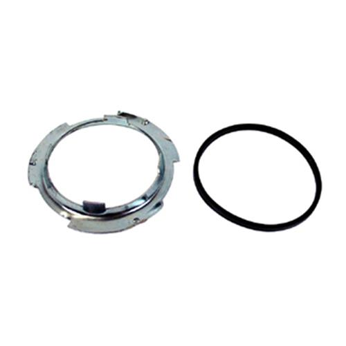
Be sure to get the lock ring and a new seal if you order the tank sender unit.
Replace your rusted or damaged 1979-1997 Mustang fuel pump lock rink and seal with this direct replacement from 5.0 Resto!
www.latemodelrestoration.com