
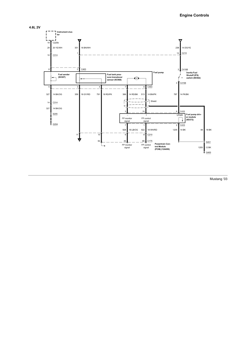
I'm troubleshooting the fuel sender for my son's 2003 GT Mustang 4.6 V-8, and could certainly use your help. Little History: I just replaced the fuel pump module. I troubleshooted the problem up to the fuel pump. He was just driving one day and the engine died out and never started up again. Before I replaced the fuel pump module, when ever his fuel gauge would read 1/4 tank, it was actually reading an empty tank, or near empty tank. This I believe is what contributed to his fuel pump failure and burning it out. At that time, he did not realize that his fuel gauge was reading incorrectly. Now, after I replaced the fuel pump module assembly, his fuel gauge reads 3/4 tank, when he tops off his fuel tank. This is what makes me think his fuel gauge is defective. I used extreme caution while installing his fuel pump module, not to bend the float arm in any way. I'm planning on looking for an after market fuel gauge, however, before I do, I want to test the ohms on the new sending unit at an empty and full tank. I most certainly don't plan on removing the fuel tank again. What a job that was. I was told by someone on one of the Mustang forums that the ohms reading for my sons car is 15 ohms full, and 160 ohms empty, can anyone confirm those spec's, good to be sure! The diagram provided here is of the fuel pump wire connector, that I got from my AllData online subscription. So, testing the sending unit, I would disconnect the fuel pump module wire connector, then I would contact pins 5 black/orange ground, and 8 yellow/white wire that runs from the sending unit to the fuel gauge, with the lowest ohms setting on my tester, is that correct? For draining out the fuel tank, if I located the Schrader valve on the fuel rail, and hooked up a fitting to the Schrader valve fitting, with a drain hose, could I simply turn the key to the on position to keep the pump working to drain out all of the fuel in the tank, is that possible? So, if the 15 and 160 ohms figures are correct, what type of gas gauge would read accurately for me? Meaning, with what parameters? Any thoughts, suggestions will be greatly appreciated. Thank you, Tommy.
You are using an out of date browser. It may not display this or other websites correctly.
You should upgrade or use an alternative browser.
You should upgrade or use an alternative browser.
Fuel pump sender specifications and testing instructions.
- Thread starter GT Tommy
- Start date
-
Sponsors (?)
93 LX
Founding Member
I am not sure about that connector pin out yo have attached but here is how I have tested my fuel float and sender. I forget exactly what the ohms are for Ford but the exact number is not important.
With the sender out of the tank you will see an arm attached to a metal box on. This box is a simple wire resistor. Using a Volt Ohm meter or Digital meter set to ohms you can test for the resistance of the sender. With then float arm at its max, upward, you should see near 10 (zero) ohms. With it down you should see between 70 or 80 ohms.
When testing move the arm up and down slowly to see if there are any places where the ohms go higher than 80. This would indicate that there are breaks in the wire or the contact is dirty. I my 82 I used some tv contrct cleaner and was able to fix my sender. It appears that old fuel can tarnish the contacts and make them stop working.
93 LX, unless the AllData publication is wrong, that is the correct pin out diagram for my sons 2003 GT Mustang 4.6 fuel pump module. As mentioned in my previous thread, I just installed this new Bosch brand fuel pump module part number 67170. I was very careful while installing the module, making absolutely sure not to bend the float arm. I also mentioned that we did have incorrect fuel gauge readings, prior to replacing the fuel pump module. There is no way that I want to remove the fuel tank again. What I plan on doing is, when ever my son gets a day off from work, he will top off his fuel tank with fuel. At that time I will take an ohms reading with the sender installed inside the tank. I then need to find a way to drain the fuel tank so I can take the empty ohms reading. I will also be troubleshooting the six ignition switch circuits. I did a quick check and found that the 2003 GT Mustang supports six circuits at their ignition switch. Two of the six circuits are tied into the Constant Control Relay Module. I believe that many Mustang owners who had after market audio, amps, video systems installed, and are now experiencing fuel related problems. They should check to see if, these after market systems are tied into anyone of the two circuits I'm talking about. I have not proven this yet, however, I strongly believe that these after market systems are depriving the fuel system of the required voltage to insure that the fuel system operates as designed. If anyone has any type of fuel related problem, such as a defective fuel pump, or incorrect fuel gauge readings, especially if it happened after installing any type of after market audio, video or amps, the first thing I would check on is to see where these systems are taking their feed from. Again, make sure they are not tied into the Constant Control Relay Module circuits. For the 2003 GT Mustang with the 4.6 V-8 engine, one of those circuits at the ignition switch is the Gray/Yellow wire, and the other is the Red/Light Green. It is probably ok to tie into any of the other four circuits at the ignition switch. I have not confirmed this yet, however, if someone else has the time, this would be a good project to work on. It would certainly answer many unanswered fuel related electrical problems. Thank you for your support, it is greatly appreciated.
AutoZone wiring diagrams, Ford Mustang 1999-2005
http://www.autozone.com/shopping/repairGuide.htm?pageId=0900c152801ef7d7
Troubleshooting the fuel gauge circuit, 1999-2004 Mustangs
According to your information , the fuel sender resistance values are 15 ohms and 160 Ohms. That means 1/2 tank is somewhere between 15 Ohms and 160 Ohms.
Since the sender uses a variable resistor, sum the resistor values of 15 & 160. That gets you 175, which you divide by 2: that gets you 87.5. So in theory, 87.5 ohms is 1/2 full. A trip to Radio Shack for the closest combination of resistors to make 87.5 ohms gets you one 68 Ohm (Catalog #: 271-1106 ) + one 22 Ohm (Catalog #: 271-1103) for a total of 90 Ohms at the cost of $2 plus tax.. Wire the resistors in series to make a resistor pack and cover it with heat shrink tubing or electrical tape. The 90 Ohms is close enough to the 87.5 Ohm figure that it shouldn't matter. Disconnect the elecrtical connector shown in your diagram. Connect one end of the resistor pack to the #8 pin on the body side electrical connector in your diagram and the other end of the resistor pack to ground. Make sure nothing is touching that isn't supposed to and turn the ignition switch to Run. If I am correct, the fuel gauge will read 1/2 full, or very close to it. If it does not, then the odds are that the gauge or anti-slosh unit are bad.
The fuel pump test/engine diagnostic connector will definitely be different since the 2003 cars are OBDII and use a different wiring scheme. I do not think there is a fuel pump test point on the 2003 cars like the one on the 87-93 cars.
Troubleshooting the fuel gauge circuit, 1999-2004 Mustangs
jrichker, yes, the electrical diagram you provided here mathces the one I have posted. I had a small typo error, I forgot to add in the orange color with the black ground wire which I just corrected. Ok, your plan sounds good. It surely simplifies things. My son is a Police Officer and uses his car for Patrol. I will have to wait till this coming weekend to do the test when he gets a day off. I will get back you you all as soon as I get the results. So, if you are correct, and the fuel gauge is defective, what type of after market fuel gauge should I purchase, with what parameters? Not sure about the anti slosh unit. His fuel gauge does work, it just that it starts off at 3/4 tank when his tank is topped off. How much voltage is suppose to be at the gauge? I'm thinking that his audio, amps and video may be tied into the Constant Control Relay Module circuit, causing a voltage drop at the gauge or within the fuel system! I will be checking on this as well. Thanks for your support, Tommy.
jrichker, yes, the electrical diagram you provided here mathces the one I have posted. I had a small typo error, I forgot to add in the orange color with the black ground wire which I just corrected. Ok, your plan sounds good. It surely simplifies things. My son is a Police Officer and uses his car for Patrol. I will have to wait till this coming weekend to do the test when he gets a day off. I will get back you you all as soon as I get the results. So, if you are correct, and the fuel gauge is defective, what type of after market fuel gauge should I purchase, with what parameters? Not sure about the anti slosh unit. His fuel gauge does work, it just that it starts off at 3/4 tank when his tank is topped off. How much voltage is suppose to be at the gauge? I'm thinking that his audio, amps and video may be tied into the Constant Control Relay Module circuit, causing a voltage drop at the gauge or within the fuel system! I will be checking on this as well. Thanks for your support, Tommy.
Troubleshooting the fuel gauge circuit, 1999-2004 Mustangs
jrichker, ok after disconnecting the wire harness connector at the fuel tank, one end of the 90 ohms resister pack goes to pin #8 the yellow/white wire on the body side, and the other end of the resister pack to ground. Do I use the ground at pin #5 black/orange wire, or do I use another ground source? Thank you, Tommy.
jrichker, ok after disconnecting the wire harness connector at the fuel tank, one end of the 90 ohms resister pack goes to pin #8 the yellow/white wire on the body side, and the other end of the resister pack to ground. Do I use the ground at pin #5 black/orange wire, or do I use another ground source? Thank you, Tommy.
Troubleshooting the fuel gauge circuit, 1999-2004 Mustangs
jrichker, I just checked Radio Shacks inventory. Now, if my fuel pump sender's full and empty ohms are 15 full and 160 empty, wouldn't it be better if I tested the gauge this way?
68 ohms - 271-1106 (resistor part numbers)
68 ohms - 271-1106
12 ohms - 271-012
12 ohms - 271-012
160 ohms total for empty reading
15 ohms- 271-1102 for full reading
Do you see what I'm asking? Let me know. Thank you, Tommy.
Most of the fuel gauge failures give a stuck on full or stuck on empty as a problem symptom. Using a resistor combination that mimics 1/2 tank allows you to decide if the gauge and anti-slosh module (if present on 2003 models) are the problem source.
If the gauge reads about 1/2 tank with the resistor combination, that points to the sender as being the culprit.
If the gauge reads full or empty with the resistor pack in place of the sender, then the gauge or anti-slosh module is at fault.
If the gauge reads about 1/2 tank with the resistor combination, that points to the sender as being the culprit.
If the gauge reads full or empty with the resistor pack in place of the sender, then the gauge or anti-slosh module is at fault.
Most of the fuel gauge failures give a stuck on full or stuck on empty as a problem symptom. Using a resistor combination that mimics 1/2 tank allows you to decide if the gauge and anti-slosh module (if present on 2003 models) are the problem source.
If the gauge reads about 1/2 tank with the resistor combination, that points to the sender as being the culprit.
If the gauge reads full or empty with the resistor pack in place of the sender, then the gauge or anti-slosh module is at fault.
Ok, got it! I should be able to perform the test this coming Saturday. I'll get back to you then. Thanks again for your support, Tommy.
94gtvert50
New Member
- May 9, 2007
- 4
- 0
- 1
Back from the dead...
I need to locate the same wires but for a different reason.
I have a racepak dash w no stock cluster. I purchased an autometer fuel level gauge. Can someone tell me what the easiest wires to hook this up to. Is it the white and yellow wire and would that be located in the stock cluster harness somewhere? Is it a one wire hookup or two?
Thanks in advance
Back from the dead...
I need to locate the same wires but for a different reason.
I have a racepak dash w no stock cluster. I purchased an autometer fuel level gauge. Can someone tell me what the easiest wires to hook this up to. Is it the white and yellow wire and would that be located in the stock cluster harness somewhere? Is it a one wire hookup or two?
Thanks in advance
Here's the diagrams. and a revised test path...

Instrument cluster connector wiring
See http://www.stangnet.com/tech/cluster87-93.pdf for information on the wiring differences, The clusters are interchangeable, but you have to do some trimming & move some wires.
You will need the Adobe Acrobat viewer which is also a free download – http://get.adobe.com/reader/
How to test and repair fuel tank gauge system
The red/yellow wire (power supply to gauge & sender) should have 12 volts when the ignition is in the start or Run position.
Troubleshooting the gauge and sender circuit:
Since the sender uses a variable resistor, sum the resistor values of 22 Ohms (empty value) & 145 Ohms (full value). That gets you 167, which you divide by 2: that gets you 83.5. So in theory, 83.5 ohms is 1/2 full. A trip to Radio Shack for the closest combination of resistors to make 83.5 ohms gets you one 68 Ohm (Catalog #: 271-1106) + one 15 Ohm (Catalog #: 271-1102) for a total of 83 Ohms at the cost of $2 plus tax. Wire the resistors in series to make a resistor pack and cover it with heat shrink tubing or electrical tape. The 83 Ohms is close enough to the 83.5 Ohm figure that it shouldn't matter. Disconnect the electrical connector shown in your for the tank sender unit. Connect one end of the resistor pack to the yellow/white wire on the body side fuel sender electrical connector and the other end of the resistor pack to ground. Make sure nothing is touching that isn't supposed to and turn the ignition switch to Run. If I am correct, the fuel gauge will read 1/2 full, or very close to it. If it does not, then the odds are that the gauge or anti-slosh unit are bad.
How and why the test works…
Most of the fuel gauge failures give a stuck on full or stuck on empty as a problem symptom. Using a resistor combination that mimics 1/2 tank allows you to decide if the gauge and anti-slosh module are the problem source.
If the gauge reads about 1/2 tank with the resistor combination, that points to the sender as being the culprit.
If the gauge reads full or empty with the resistor pack in place of the sender, then the gauge or anti-slosh module is at fault.
Fuel gauge sender testing and replacement
The next steps require dropping the fuel tank and removal of the fuel level sender. Here are some useful tips...
I have done the tank removal three times, and the main issues are getting the car up on jack stands and getting the gas out of the tank. DO NOT try to do this job without jack stands. Becoming a pancake is not part of the repair process.
Pumping out the old gas:
If the old pump still works, you can use it to pump the tank out.
1.) Separate the pressure line (the one with the Schrader valve on it) using the fuel line tools.
Look in the A/C repair section for the fuel line tools. They look like little plastic top hats. You will need the 1/2" & 5/8" ones. The hat shaped section goes on facing the large part of the coupling. Then you press hard on the brim until it forces the sleeve into the coupling and releases the spring. You may need someone to pull on the line while you press on the coupling.
OR
View: https://www.youtube.com/watch?v=vRTjYAxvaCs
Use a piece of garden hose to run from the pressure line to your bucket or gas can. Make sure it is as leak proof as you can make it. Fire and explosion are not part of the repair process...
2.) Jumper the fuel pump test point to ground.
Turn the ignition switch to the Run position. the fuel pump will pump the tank almost dry unless the battery runs down first.
Some 5 gallon paint pails lined with garbage bags are good to hold the gas. The garbage bags provide a clean liner for the pails and keep the loose trash out of the gas so you can reuse it. If you decide to use a siphon, a piece of 1/2" garden hose stuck down the filler neck will siphon all but a gallon or so of the gas.
Remove the filler neck bolts and put them in a zip bag. Disconnect the supply & return lines by removing the plastic clips from the metal tubing. If you damage the clips, you can get new ones form the auto part store for just a few dollars. I have used tie-wraps, but that is not the best choice. Then you remove the two 9/16" nuts that hold the T bolts to the straps. Put the nuts in the zip bag with the filler bolts. Pull the plastic shield down and away from the tank. Once the tank drops a little bit you can disconnect the wiring for the pump & fuel quantity sender.
The fuel gauge sender assembly comes out by removing a large metal ring that unscrews from the tank. There is a separate mounting/access plate for the fuel pump and fuel gage. You are supposed to use a brass punch to tap on the ring so that you don't make sparks. Look closely at the rubber O ring gasket when you remove the fuel gauge sender.
When you install the metal ring that holds the sender in place, watch out for the gasket O ring. Some RTV may be helpful if the ring is not in excellent condition.
The tank to filler pipe seal is a large rubber grommet. Inspect it for hardening, tears and damage. At $20 from the Ford dealer, it might be a good idea to replace it.
I used a floor jack to help lift the tank back in place. You may find that it is the only time you really can make good use of a helper.
All resistance measurements should be made with the power off.
Note from bstrd86 - 86 and older fuel tank sender units are 73 ohms empty, 8-12 ohms full.
The yellow/white wire will show a voltage that varies with the movement of the float on the sender unit. To test the sender, set your Ohmmeter or DVM on low Ohms. Then disconnect the sender and connect the Ohmmeter or DVM to the yellow/white and black wires from the sender unit. Move the float arm while watching the Ohmmeter or DVM. You should see the reading change from 22 to 145 ohms +/- 10%.
If the Ohmmeter or DVM resistance readings are way off, replace the tank sender unit.
Use extreme caution if you do the next step. Fumes from the gas tank can easily ignite and cause a fire or explosion.
With the sender unit out of the tank and connected to the body wiring harness, turn the ignition switch to the Run position. Move the float arm and the fuel gauge indicator should move. If you are very careful, you can use a pair of safety pins inserted in the connector for the yellow/white and black wires to measure the voltage as you move the float arm. The voltage will change, but I have no specs for what it should be.
Do not short the safety pins together or to ground. If you do, you may damage the anti-slosh module or crate a spark. A spark with the fuel tank open could cause a fire or an explosion.
If the voltage does not change and the tanks sender passed the resistance tests, the anti-slosh module or gauge is bad.
Anti-Slosh module pictures courtesy of Saleen0679

Copied from DrBob
I worked on an 88 Mustang today that had similar symptoms. Short version, I took the “anti slosh module” off of the back of the instrument cluster and replaced the electrolytic capacitor. Fixed it for $1.39 with a part from Radio Shack.
In an attempt to help other folks, here’s the long version.
Remove the “anti slosh module” located on the back of the instrument cluster. There was a single Torx screw holding mine to the cluster.
Find the electrolytic capacitor. It will be the largest, 2 wire component on the board. The capacitor may have a red or blue plastic wrapper on it. Mine was red.
The wrapper should have printing on it. Look for printing that looks something like this:
100uF+25V
The “100uF” tells you this is a 100 micro Farad capacitor. The “+25V” tells you the capacitor is rated for 25 Volts. Yours may be different. You may use a higher voltage part but don't use a lower rated voltage part. If you use a lower voltage part the capacitor might open later on down the road or it could be as bad as catching fire.
If you can’t find the printing you’ll need to remove the part. You have to anyway so nothing wasted. However pay close attention to the way the capacitor is oriented on the board.
One end of the capacitor will be bare metal with a wire sticking out. The other end should have some sort of insulation over it with a wire sticking out. The bare metal end is the negative end while the insulated end is the positive end. Pay attention to which end is connected to which hole on the board.
Get a replacement part. I got mine at Radio Shack, $1.39. Here’s the info:
100µF 35V 20% Axial-Lead Electrolytic Capacitor
Model: 272-1016 | Catalog #: 272-1016
Fuel tank sender unit:
http://www.latemodelrestoration.com/products/Mustang-Gas-And-Fuel-Tank-Sending-Unit
Be sure to get the lock ring and a new seal if you order the tank sender unit.
http://www.latemodelrestoration.com...ng-Fuel-Pump-Sending-Unit-Lock-Ring-And-Seal\
Last edited:
603mustangs
Advanced Member
I found the yellow/white wire under drivers seat against rocker panel under carpet. My seat was already removed, and far easier than dropping fuel tank or instrument cluster. If you open the loom you'll find it, it's one of the biggest of all the wires. Cut that wire and do resistance test from there. I had a pack of 4 - 40ohm resistors, as I added each one the gauge went up 1/4 tank. So sending unit is bad. Good knowing I'm not removing tank or instrument cluster for a 50/50 shot at the problem. Thanks for the article.

Similar threads
- Replies
- 27
- Views
- 1K
- Replies
- 5
- Views
- 831
- Replies
- 2
- Views
- 274
- Replies
- 3
- Views
- 267
- Replies
- 5
- Views
- 1K