Hello this is my first post. I just got a 92 5.0 convertible with automatic trans. The car supposedly ran when parked approximately 10 yes ago. I bought it along with a 88 gt hatch with no motor. My plan was to put the motor and trans from the 91 into the 88 but I wanted to get it running first..
The car will crank and will run with starting fluid. The fuel pump runs constantly with key on and there is a very faint CEL. The CEL is bright and constant while cranking. I have checked the pip with a led light probed on the first wire of the tfi and I get flashes as engine cranks over. I then went to check for 5v ref at the salt and pepper plugs on top of the engine. I have no voltage on pin 2 but have 5.35 volts on pins 7 and 8 which are for the oil and temp gauges.
I have no idea why there would be voltage on those pins. I have tried to pull engine codes using the CEL and using a test light and can't get it to give any codes. I disconnected the brown plug at driver side fender and ran a jumper for the red/green tracer wire to power the computer and there is no longer 5 volts on those pins but nothing on pin 2 either. I have tried a different ecm with the same results. Any help would be greatly appreciated.
Computer will not go into diagnostic mode on 91-95 model 5.0 Mustangs
Revised Dec 23 2017
1.) To clarify signal ground connections on the engine mounted fuel injector wiring harness and add diagram for the engine mounted fuel injector wiring harness
2.) To add warning about using an automatic transmission O2 sensor wiring harness with a A9L manual shift transmission computer.
How it is supposed to work:
The grey/red wire (pin 46) is signal ground for the computer. It provides a dedicated ground for the EGR, Baro, ACT, ECT, & TPS sensors as well as the ground to put the computer into self-test mode. As long as you are successful dumping the codes by using the gray/red wire on the diagnostic connector for the ground when dumping, the computer’s internal ground on pin 46 is good.
If this ground is bad, none of the sensors mentioned will work properly. That will severely affect the car's performance. You will have hard starting, low power and drivability problems. Since it is a dedicated ground, it passes through the computer on its way to the computer main power ground that terminates at the battery pigtail ground. It should read less than 1 ohm when measured from anyplace on the engine harness with the battery pigtail ground as the other reference point for the ohmmeter probe.
Engine mounted fuel injector wiring harness sensors for a 5.0 mustang
What sometimes happens is that the test connector grey/red wire gets jumpered to power which either burns up the wiring or burns the trace off the pc board inside the computer. That trace connects pins 46 to pins 40 & 60.
OR
If an O2 sensor harness from an automatic transmission Mustang is used with an A9L manual shift transmission computer. The 12 volts from the automatic transmission starter circuit will damage the A9L computer.
The STI (Self Test Input) is jumpered to ground to put the computer into test mode. Jumpering it to power can produce unknown results, including damage to the computer. The ohm test simply verifies that there are no breaks in the wiring between the test connector and the computer input.
How to test the wiring :
With the power off, measure the resistance between the computer test ground (grey/red wire) on the self- test connector and battery ground. You should see less than 1 ohm.
If that check fails, remove the passenger side kick panel and disconnect the computer connector. There is a 10 MM bolt that holds it in place. Measure the resistance between the grey/red wire and pin 46 on the computer wiring connector: it should be less than 1 ohm. More than 1 ohm is a wiring problem. If it reads 1 ohm or less, then the computer is suspect. On the computer, measure the resistance between pin 46 and pins 40 & 60: it should be less than 1 ohm. More than that and the computer’s internal ground has failed, and the computer needs to be repaired or replaced.
See image below for help finding the burnt signal ground trace.
The fix is some careful soldering of a small jumper wire across the burnt section of copper trace.
While you have the computer connector disconnected from the computer, turn the ignition switch to the Start position and look for 12 volts on pin 46 of the computer wiring harness. If you see 12 volts then you have an automatic transmission O2 sensor harness. That will damage the A9L manual shift transmission computer.
If the first ground check was good, there are other wires to check. Measure the resistance between the STI computer self-test connector (red/white wire) and pin 48 on the computer main connector: it should be less than 1.5 ohms. More than 1 ohms is a wiring problem
The following is a view from the computer side of the computer wiring connector: it is for an A9L, A9P computer.
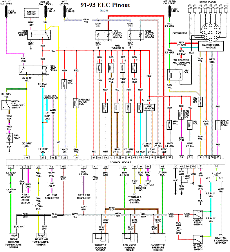
Diagram courtesy of Tmoss & Stang&2birds
Check out the diagram and notice all the places the grey/red wire goes. Almost every sensor on the engine except the MAF is connected to it.
91-93 5.0 Mustangs
Complete computer, actuator & sensor wiring diagram for 94-95 Mass Air Mustangs
See the graphic for the 10 pin connector circuit layout.
See the following website for some help from Tmoss (diagram designer) & Stang&2Birds
(website host) for help on 88-95 wiring
http://www.veryuseful.com/mustang/tech/engine


