Engine New bigger throttle body

Scott7512

Active Member
May 19, 2015
153
8
38
Branchland WV
Just changed heads from gt40p to afr 165. Changed intake to edelbrock performer rpmll. New 4 hole 24lb injectors in place of the 24lb single hole. New 70mm throttle body replacing the 65mm explorer one.
Bama tells me that I don’t need a new tune.
I am getting a code 66 maf signal too low. Maf is a pro-m calibrated for 24lb injectors and is less than 2 years old.
Any thoughts?
 
  • Sponsors (?)


Just changed heads from gt40p to afr 165. Changed intake to edelbrock performer rpmll. New 4 hole 24lb injectors in place of the 24lb single hole. New 70mm throttle body replacing the 65mm explorer one.
Bama tells me that I don’t need a new tune.
I am getting a code 66 maf signal too low. Maf is a pro-m calibrated for 24lb injectors and is less than 2 years old.
Any thoughts?

Code 66 or 157 MAF below minimum test voltage.

Revised 2 Nov 2019 to add details on MAF testing

Insufficient or no voltage from MAF. Dirty MAF element, bad MAF, bad MAF wiring, missing power to MAF. Check for missing +12 volts on this circuit. Check the two links for a wiring diagram to help you find the red wire for computer power relay switched +12 volts. Check for 12 volts between the red and black wires on the MAF heater (usually pins A & B). while the connector is plugged into the MAF. This may require the use of a couple of safety pins to probe the MAF connector from the back side of it.

Computer wiring harness connector, wire side.
71316.gif


Computer wiring harness connector, computer side.
88243.gif


Diagrams courtesy of Tmoss and Stang&2Birds

ECC Diagram for 88-90 5.0 Mustangs
88-91_5.0_EEC_Wiring_Diagram.gif


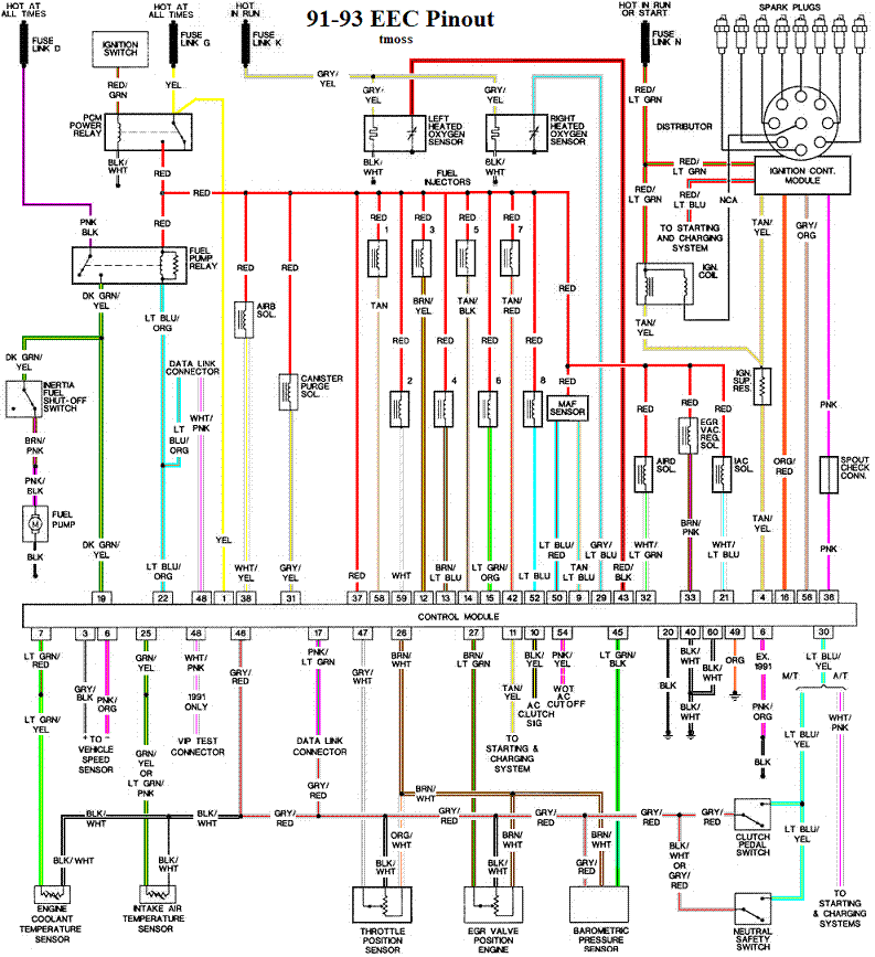
ECC Diagram for 91-93 5.0 Mustangs
91-93_5.0_EEC_Wiring_Diagram.gif


94-95 Diagram for 94-95 5.0 Mustangs[/b]
94-95_5.0_EEC_Wiring_Diagram.gif


How the MAF works

There are three parts in a MAF: the heater, the sensor element and the amplifier. The heater heats the MAF sensor element causing the resistance to increase. The amplifier buffers the MAF output signal and has a resistor that is laser trimmed to provide an output range compatible with the computer's load tables. Changes in RPM causes the airflow to increase or decrease, changing the voltage output. The increase of air across the MAF sensor element causes it to cool, allowing more voltage to pass and telling the computer to increase the fuel flow. A decrease in airflow causes the MAF sensor element to get warmer, decreasing the voltage and reducing the fuel flow.

Actually, MAF pins C & D float with reference to ground. The signal output of the MAF is a differential amplifier setup. Pins C & D both carry the output signal, but one pin's output is inverted from the other. The difference in signal between C & D is what the computer's input circuit is looking for. The difference in the two outputs helps cancel out electrical noise generated by the ignition system and other components. Since the noise will be of the same polarity, wave shape and magnitude, the differential input of the computer electronically subtracts it from the signal. Then it passes the signal on to an Analog to Digital converter section inside the computer's CPU chip.

The MAF element is secured by 2 screws & has 1 wiring connector. To clean the element, remove it from the MAF housing and spray it down with electronic parts cleaner or non-inflammable brake parts cleaner (same stuff in a bigger can and cheaper too).

89-90 Model cars: Measure the MAF output at pins C & D on the MAF connector (dark blue/orange and tan/light blue) or at pins 50 & 9 on the computer. Be sure to measure the sensor output by measuring across the pins and not between the pins and ground.
attachments\205136\


91-95 Model cars: Measure the MAF output at pins C & D on the MAF connector light blue/red and tan/light blue) or at pins 50 & 9 on the computer. Be sure to measure the sensor output by measuring across the pins and not between the pins and ground.

MAF output readings: Use the computer connector diagram to help choose the proper pin connection on the computer when measuring the MAF output voltage. The idling voltage check can the done with the voltmeter directly stuck in the backside of the MAF connector.

At idle = approximately .6 volt
20 MPH = approximately 1.10 volt
40 MPH = approximately 1.70 volt
60 MPH = approximately 2.10 volt

If the output of the C&D pins exceeds the specs above, there are two possible problems:

1.) The MAF sensor is defective and needs to be replaced.
2.) The MAF sensor is installed in a different housing than the one it was designed for. The sensor is designed to work with a specific MAF part number or model MAF housing.

Check the resistance of the MAF signal wiring
For the next 2 checks make your measurement with the MAF disconnected from the wiring harness.

Pin D on the MAF wiring harness and pin 50 on the computer (dark blue/orange wire) should be less than 2 ohms. Pin C on the MAF wiring harness and pin 9 on the computer (tan/light blue wire) should be less than 2 ohms.

There should be a minimum of 10K ohms between either pin C or D on the MAF wiring connector and pins A or B.

Reconnect the MAF to the wiring harness and proceed to the next section.


See the following website for some help from Tmoss (diagram designer) & Stang&2Birds (website host) for help on 88-95 wiring http://www.veryuseful.com/mustang/tech/engine/

Ignition switch wiring
http://www.veryuseful.com/mustang/tech/engine/images/IgnitionSwitchWiring.gif

Fuel pump, alternator, ignition & A/C wiring
http://www.veryuseful.com/mustang/tech/engine/images/fuel-alt-links-ign-ac.gif

Computer, actuator & sensor wiring
http://www.veryuseful.com/mustang/tech/engine/images/88-91_5.0_EEC_Wiring_Diagram.gif

Fuse panel layout
http://www.veryuseful.com/mustang/tech/engine/images/MustangFuseBox.gif

Vacuum routing
http://www.veryuseful.com/mustang/tech/engine/images/mustangFoxFordVacuumDiagram.jpg
 
  • Like
Reactions: 1 user
Here’s a video Of the problem. Not sure if it has anything to do with the maf. Sometimes it shuts off completely. I bypassed the msd box and it still does it. The ecu has had a chip in it for over 2 years and has not been doing this. But it may have developed a problem. The capacitors in the ecu have been replaced.
 
Here’s a video Of the problem. Not sure if it has anything to do with the maf. Sometimes it shuts off completely. I bypassed the msd box and it still does it. The ecu has had a chip in it for over 2 years and has not been doing this. But it may have developed a problem. The capacitors in the ecu have been replaced.
Can’t get video loaded from this phone
 
You've got to upload the video to youtube...then hit share...click clipboard...come here and paste it in the thread text box. Videos don't don't straight from phone or pc.
 
  • Useful
Reactions: 1 user
Pulled the chip and the intermittent cut off is gone.
But, took it down the road and now I have another problem.
Got on it a bit in 2nd and had a loud pop that sounds like it is in the exhaust. Got on it again and another pop. Drove it normally back home. Previously before drive test, I was reving it out in the garage and it popped and shot a flame out the exhaust. My son and I thought it was cool. I checked codes and one was for running rich. I have set and verified timing at 12.
These things have came up after a head and intake install. Larger throttle body and off brand 24lb injectors.
 
I have 7 injectors. Dropped one and damaged it’s tip. They were rebuilt Ford 24lb.
Checked fuel pressure with vacuum unhooked from regulator and it was 41. I put it down to 38.
Warmed it up and took a drive with the same popping sound and sluggish feeling.
I am going to pull codes and see what’s there and post it.
 
I thought it was supposed to be 39 with the vacuum pulled off and plugged.
It is from the exhaust. My son thought it was cool when a flame shot out of it the first time it happened.
Car idles steady.
Pulled codes from last drive and got 81 82 84 O and 33 C. My egr stuff is gone.
 
Just a recap of what’s going on.
Car ran good with only a random problem here and there.
Decided to do an upgrade on heads and intake.
Installed afr 165 heads and edelbrock rpm II intake.
After install car ran great but would shut off for a split second every once in a while.
I started figuring this out and found after taking out the sct chip, the intermittent cut off was gone.
During test drive the loud popping while under heavy load showed up. Driving it normal there is no popping.
 
The fuel pressure is supposed to be 42+- with the vac line off,plugged and engine running, 32-34 ish vac line on engine running.
I forgot, is it poping in the exhaust or the intake?
Fuel pump pressure & regulator test

Check fuel pressure:
The local auto parts store may rent or loan a fuel pressure test gauge if you don't have one.

Disconnect the vacuum line from the fuel pressure regulator. Check it for evidence of fuel present in the line by removing it and blowing air through it. If you find fuel, the fuel pressure regulator has failed. Reinstall the line; leave the fuel pressure regulator end of the vacuum line disconnected. Then cap or plug the open end of the vacuum line and stow it out of the way.

Connect the fuel pressure test gauge to the Schrader port located just behind the alternator.
Turn the ignition switch on & start the engine. Observe the pressure: you should see 37-41 PSI at idle.
Turn the ignition off; reconnect the vacuum line to the fuel pressure regulator. Then disconnect the fuel pressure test gauge. Watch out for squirting gas when you do this.

Fuel pump pressure test
Disconnect the larger of the two fuel lines up by the Schrader valve. It is the return line and does not have the Schrader valve on it. Find a piece of rubber fuel hose and clamp it on the return line coming from the regulator. Stick a bolt in the other end of the hose and make sure that all your connections are tight and leak proof as possible. When this powers up, you don't want fuel squirting everywhere. Hook up the fuel pressure test gauge. Turn the ignition switch on and watch for leaks. You may want to use a helper inside the car to cut the switch off quickly if you have a leak. To trick the fuel pump into running, find the EEC test connector and jump the connector in the Upper RH corner to ground.

attachments\68357


Caution!!! You have blocked the return line for the fuel pump! Pressure will rise very quickly past safe levels with a good pump
If the pressure goes up past 55 PSI, the pump is good and the fuel pressure regulator is bad. If the fuel pressure does not hit 55 PSI or more in a few seconds, the pump is bad or you have electrical problems.
 
  • Informative
Reactions: 1 user
Ok here is what I have determined.
Replaced coil with my spare and tested plug wires.
No change. Still backfire in exhaust.
Put in my spare sct chip.
Still backfire and now cutting out is back.
Took chip back out.
Decided to put 65mm throttle body back on. When I took off the 70mm off I found oil puddle behind it in the intake spacer and oil mist all over the throttle blade on the filter side.
My thought is that my air filter is too small/restrictive and sucking oil mist through the tube going to the oil filler neck.
I removed the air filter and the hose on intake and plugged it.
Did a test drive and no big bog or backfire. But it seemed like it was not completely happy with no filter.
Bumped timing up to 13 and drilled a few holes in the end of the cone filter.
Did another test drive and all seems good.
Now I need to find my ideal air filter.
Other than the sct chips not playing well with the computer, I can hardly believe that a restrictive air filter could cause me so much grief.
I will be doing more testing after I get a new filter and report back.
 
MAF meter on CAI system that needs clocking or protection from engine compartment air turbulence. A cone type filter located inside the engine compartment is almost sure to have surge problems due to the hot, turbulent airflow around it.

Don't do this: it is a big NO NO.


598467_4134113989910_148597054_n-jpg.79437.jpg


Try cleaning the MAF element & then "clock" the MAF by rotating the entire MAF housing to see if changing its position helps.
 
Nowhere do I see where you have checked maf voltage, did you read through a do the checks list by jrichker or are you going to just swap parts around hoping to fix it?
 
Checked idle maf voltage and it was good. Changes with increase in rpm. Did not check it per mph. It’s a pro-m unit with less than 5k miles on it.
Would a bad maf cause oil to be puddling just behind the the throttle body blade and coating the filter side of the blade?