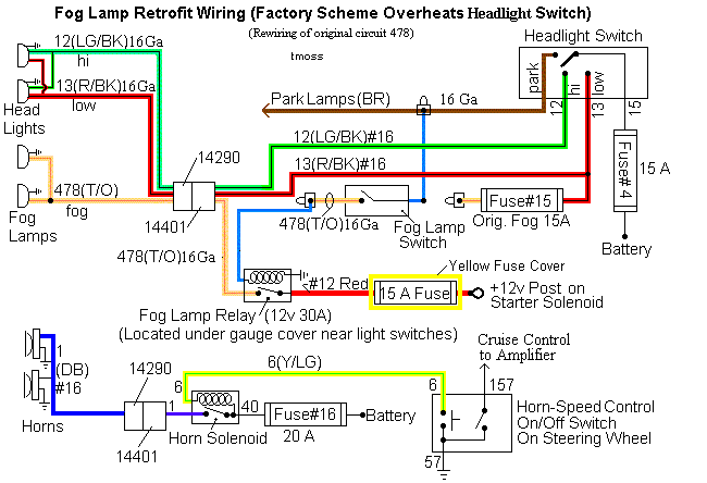
Diagrams courtesy of Tmoss & Stang&2birds
Main lighting power, dimmer, headlights and radio lighting wiring diagram
Upgraded Foglight wiring diagram
SEE
Mustang GT Fog Light Fix to fix the foglight problem. The stock wiring isn't up to the job and is overheating. The headlight switch & turn/multifunction switch are affected by Ford's wiring problem. Sometimes it overheats so badly that the plastic shells of the wiring connectors start to melt. This will show you how to add a relay to the fog lights to relieve the overload on the headlight wiring.
Be careful not to use bulbs rated at more than 55 watt each with the stock fog light wiring. Using oversize bulbs can result in overheating the wiring harness and electrical fires. Definitely do the fog light fix first.
I did mine differently, but I had to build my own wiring harness for the fog lights. This is more trouble than it is worth for most folks. I left all the wiring on the stock light switches in place and used the fog light wiring to power the relay coil. The other side of the relay coil is connected to ground. I have an inline fuse that picks up power from the battery side of the starter solenoid. It is connected to the relay contact. The other relay contact is connected to the new wiring harness I made for the fog lights.
The advantage of making your own foglight wiring harness is that you can run 100 watt fog light bulbs. The stock wiring harness will not use 100 watt bulbs without overloading and causing a fire.
Unless you are good at electrical wiring, have the skills and tools (crimp tool, soldering gun, heat gun for the heat shrink tubing, etc.) I recommend that you stick with the Corral method.
Technical explanation of why the wiring and switches overheat.
You asked for it...
I= Current
E= Voltage
R= Resistance
W= Watts
Two 55 watt fog lamps =110 watts. Find the current in the circuit
I= W/E
110 watts/14 volts = 7.85 amps for fog lights alone.
Since the lighting circuit supplies headlights, taillights, and parking lights, etc.
56 watts 2 each GE Part # L3156 corner light 28 watts each
90 watts 2 each GE Part # 9004 headlight 45/65 watts each (low beam)
63 watts 2 each GE Part # L194 parking light 31.5 watts each
56 watts 2 each GE Part # L3157 tail light 28 watts each
265 watts Total
Total other exterior lighting current
I=W/E
265 watts/14 volts = 18.92 amps
18.92 amps other exterior lighting current
+ 7.85 amps fog light current
26.77 amps with all exterior lights and fog lights on.
The 12 gauge power feed wire to the exterior lighting switch is rated at 20 amps
26.77
- 20.00
6.77 amps excess current
7.85 amps used by fog lights
-6.77 amps excess current
1.08 amps to run the fog lights left if you stay within the 20 amp limit of the wire.
With 1.08 amp of current, the fog lights probably won’t produce any useable light.
Added resistance required to reduce fog light current to permissible 20 amp limit
R=E/I
14 volts/6.77 amps = 2.06 ohms
Resistor wattage
W=EI
14 volts x 6.77 amps = 94.78 watts
You would need a 2 ohm, 100 watt resistor.
Light bulb ratings from
http://www.roadparts.com/catalog/section30.pdf
Radio shack resistor catalog - no matches , and no combinations that could be used to make a 100 watt, 2 Ohm resistor.
See
RadioShack.com
Ohm’s law – in case you have any questions about my formulas -
Ohm's Law Calculators
See the following website for some help from Tmoss (diagram designer) & Stang&2Birds (website host) for help on 88-95 wiring;
http://www.veryuseful.com/mustang/tech/engine/ Everyone should bookmark this site.
94-95 Mustang wiring diagrams
http://www.veryuseful.com/mustang/tech/engine/#95-95Diagrams
Complete computer, actuator & sensor wiring diagram for 91-93 Mass Air Mustangs
http://www.veryuseful.com/mustang/tech/engine/images/91-93_5.0_EEC_Wiring_Diagram.gif
Complete computer, actuator & sensor wiring diagram for 88-91 Mass Air Mustangs
http://www.veryuseful.com/mustang/tech/engine/images/88-91_5.0_EEC_Wiring_Diagram.gif
Ignition switch wiring
http://www.veryuseful.com/mustang/tech/engine/images/IgnitionSwitchWiring.gif
Fuel, alternator, A/C and ignition wiring
http://www.veryuseful.com/mustang/tech/engine/images/fuel-alt-links-ign-ac.gif
O2 sensor wiring harness
http://www.veryuseful.com/mustang/tech/engine/images/mustangO2Harness.gif
Vacuum diagram 89-93 Mustangs
http://www.veryuseful.com/mustang/tech/engine/images/mustangFoxFordVacuumDiagram.jpg
HVAC vacuum diagram
http://www.veryuseful.com/mustang/tech/engine/images/Mustang_AC_heat_vacuum_controls.gif
TFI module differences & pin out
http://www.veryuseful.com/mustang/tech/engine/images/TFI_5.0_comparison.gif
Fuse box layout
http://www.veryuseful.com/mustang/tech/engine/images/MustangFuseBox.gif
Mustang 5.0 Lights and Radio schematic, by TMoss:
http://www.veryuseful.com/mustang/tech/engine/images/mustangFoxLights-Radio_diag.gif
87-92 power window wiring
http://www.veryuseful.com/mustang/tech/engine/images/mustang87-92 PowerWindowWiring.gif
93 power window wiring
http://www.veryuseful.com/mustang/tech/engine/images/mustang93PowerWindows.gif
T5 Cutaway showing T5 internal parts
http://www.veryuseful.com/mustang/tech/engine/images/5_Speed_Cutaway_Illustrated.jpg
Visual comparison of the Ford Fuel Injectors, picture by TMoss:
http://www.veryuseful.com/mustang/tech/engine/images/Ford_Injector_Guide.jpg
Convertible top motor wiring
http://www.veryuseful.com/mustang/tech/engine/images/mustang88VertTopMotorCkt.gif
Engine mounted fuel injector harness
http://www.veryuseful.com/mustang/tech/engine/images/mustangEngineHarness.gif tang/tech/engine/images/mustang88VertTopMotorCkt.gif[/b]


