yet another 3G question (cant find what i need)

hey guys,
I know theres a ton of info on the 3G alternator swap but i just cant find what I"m looking for. So here goes i hope you guys can help me i have my battery swaped to my trunk with a Summit brand master disconnect battery switch mounted on the back bumper, this switch is only rated at continuous 20amp and a surge amp rating of 125, and if i get this right to make the switch work properly i would run my 4gauge wire to the on side of the switch so when positioned to the off spot it kills both battery and alternator power. There for do i need to upgrade the kill switch to something of a higher rating (above 130amps) or will this switch be fine. I have not started the car yet so i dont know if this switch will hold its own or it will crap out on me, has anyone ever had this type of thought before or just me? thanks alot.
Tim
 
  • Sponsors (?)


For a battery cut off switch, see
http://www.moroso.com/catalog/categorydisplay.asp?catcode=42225 is the switch
http://www.moroso.com/catalog/images/74102_inst.pdf
Use the super duty switch and the following tech note to wire it and you
will be good to go.

Use the Moroso plan for the alternator wiring and you risk a fire.
The 10 gauge wire they recommend is even less adequate that
the stock Mustang wiring.

There is a solution, but it will require about 40' of 18 gauge green wire.

Wire the battery to the two 1/4" posts as shown in the diagram.

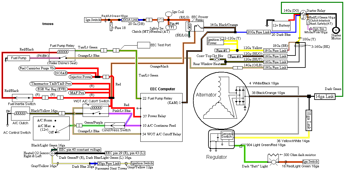
The alternator requires a different approach. On the small alternator plug
there is a green wire. On the diagram it is #904, lt green/red wire that connects
to the alternator and dash light. It is the sense lead that turns the regulator on
when the ignition switch is in the run position. Cut the green wire and solder the
40' of green wire between the two pieces. Use some heat shrink to cover the
splices. See http://fordfuelinjection.com/?p=7 for some excellent
help on soldering & using heat shrink tubing.

Run the green wire back to the Moroso switch and cut off the excess wire.
Try to run the green wire inside the car and protect it from getting cut or
chaffed. Crimp a 18 gauge ring terminal (red is 18 gauge color code for the crimp
on terminals) on each wire. Bolt one ring terminal to each of the 3/16" studs.
Do not add the jumper between the 1/4" stud and the 3/16" stud as shown it the
Moroso diagram.

How it works:
The green/red wire is the ignition on sense feed to the regulator. It supplies
power to the regulator when the ignition switch is in the run position. Turn
the Moroso switch to off, and the sense voltage goes away, the voltage
regulator shuts off and the alternator quits making power.

See the following website for some help from Tmoss (diagram designer) &
Stang&2Birds (website host) for help on 88-90 wiring and lots more…

http://www.veryuseful.com/mustang/tech/engine/images/IgnitionSwitchWiring.gif

http://www.veryuseful.com/mustang/tech/engine/images/fuel-alt-links-ign-ac.gif

http://www.veryuseful.com/mustang/tech/engine/images/88-91eecPinout.gif

Diagram courtesy of Tmoss and Stang&2birds.
fuel-alt-links-ign-ac.gif
 
hey,
well thanks alot for the reply im gunna take a good look at it and see if i can figure out what how this this is saposed to wired, So are you saying the way i had it was the wrong way to wire up the switch totaly?thanks for the help
Tim