You are using an out of date browser. It may not display this or other websites correctly.
You should upgrade or use an alternative browser.
You should upgrade or use an alternative browser.
Resource icon
1988 Mustang GT Restoration/Modification
- Author RacEoHolic330
- Creation date
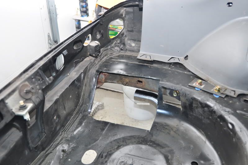
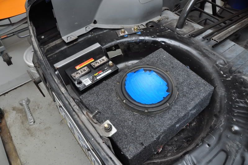
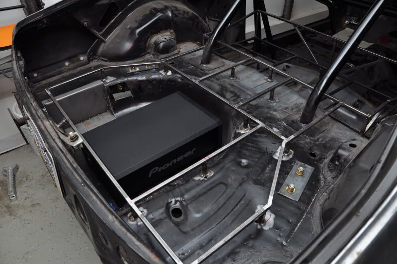
I wanted to mount the battery in the rear to keep the engine bay clean, but I didn't want it in a huge battery box sitting in the corner of the hatch. Because of my desire to have a subwoofer in the spare tire well, there really isn't enough room to squeeze a battery in there too. While pondering solutions to my dilemma, I discovered a void between the driver side spare tire well and the frame rail. I've been on a cutting and welding kick lately, so naturally, I did some more cutting and welding...
Cut the spare tire well to the general width of a car battery:
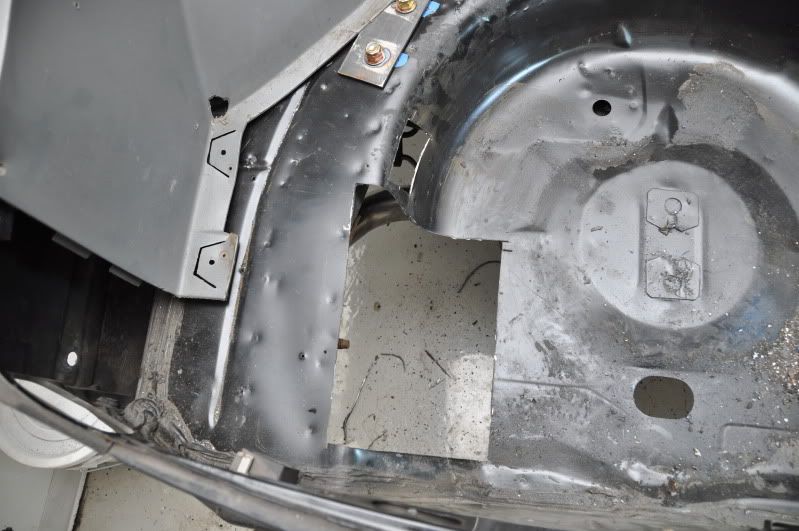
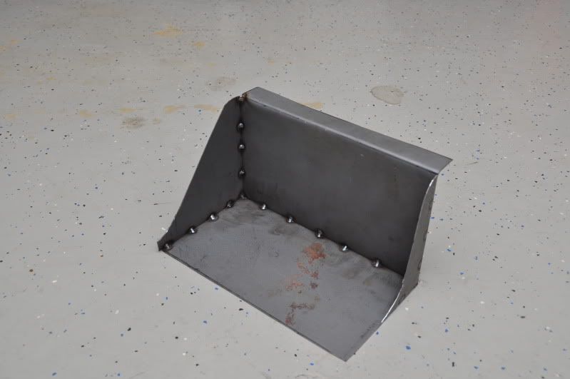
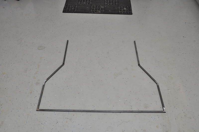
I needed to fabricate a box that would let me cheat the battery closer to the framerail. Here is what I came up with:
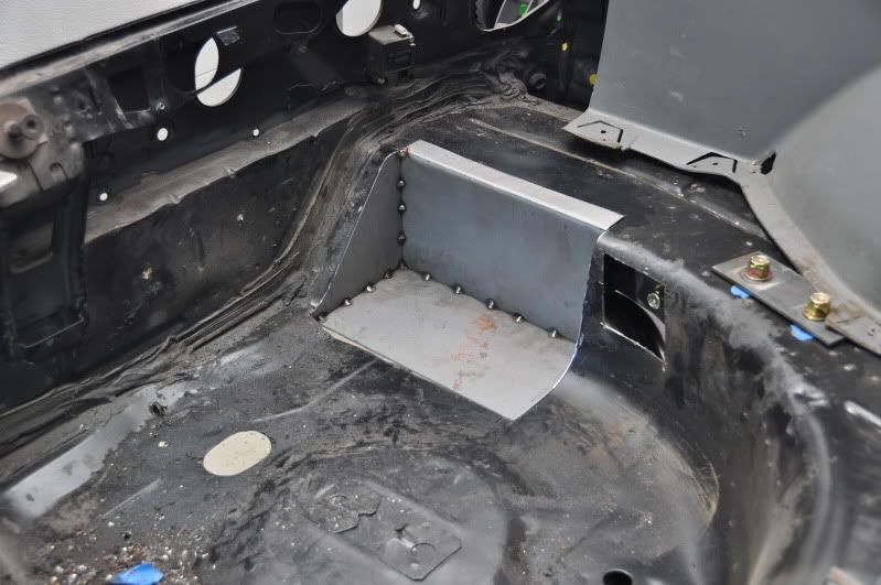
Mocked up:
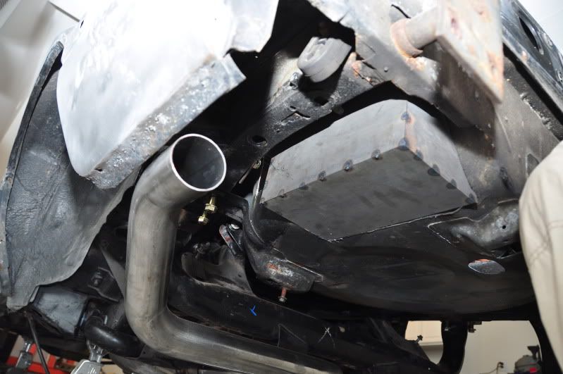
Here is why I needed to push the battery as far over as I could:
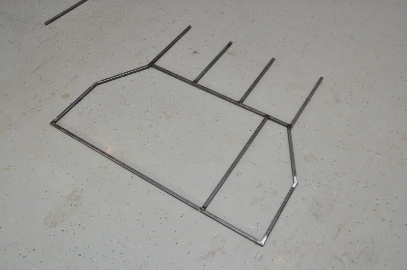
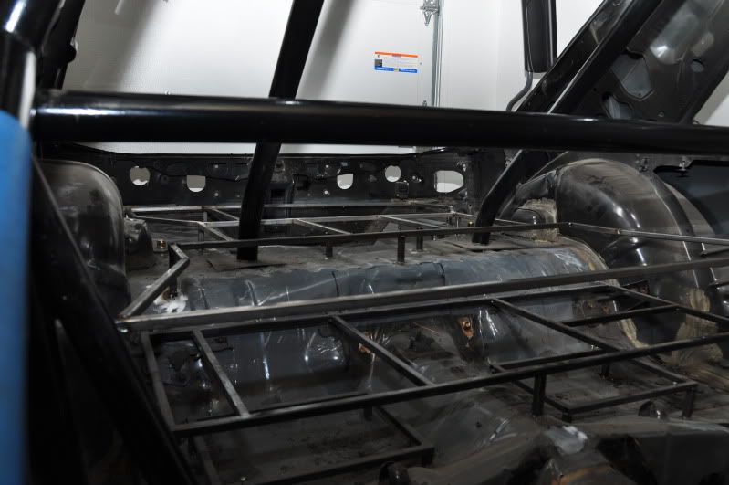
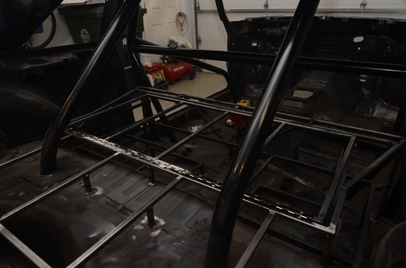
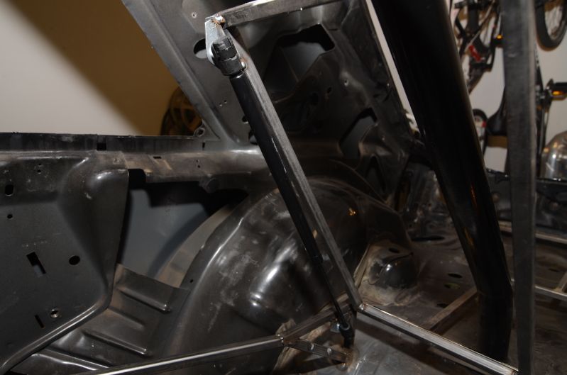
Below is the construction of the false floor. Framed it all out of 1/2" square steel stock. I decided to elevate the level of the floor frame 2" above the hatch floor. This will give me plenty of room for the subwoofer as well as clearance for a battery as tall as an Optima Red, if I decide to get one down the road.
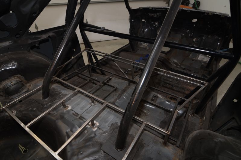
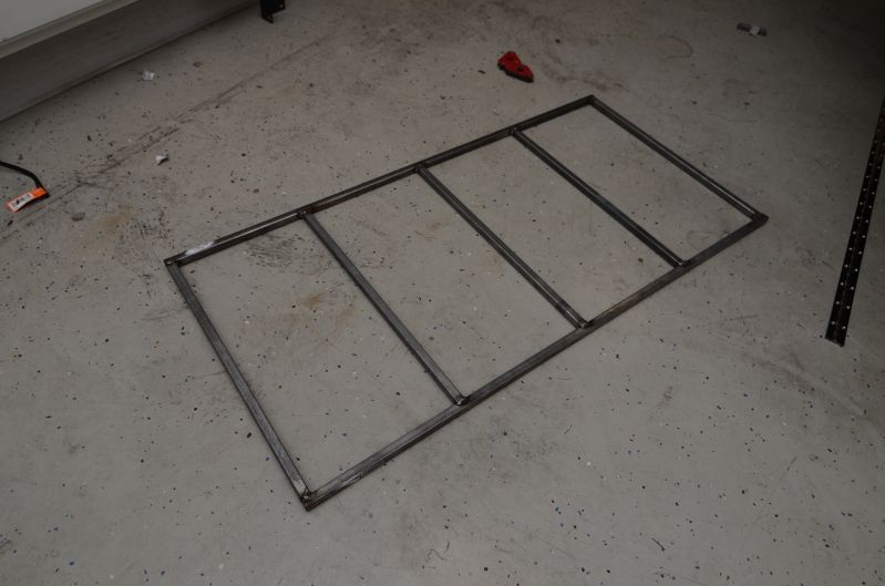
Here's some of the outer frame for the back half of the hatch:
I had to leave the top end open so I can fit it around the roll bar. The front brace had to be welded in the car.
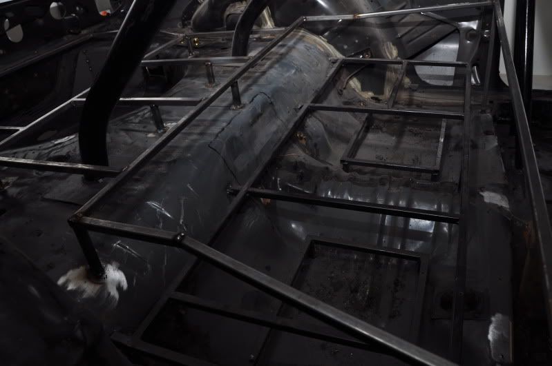
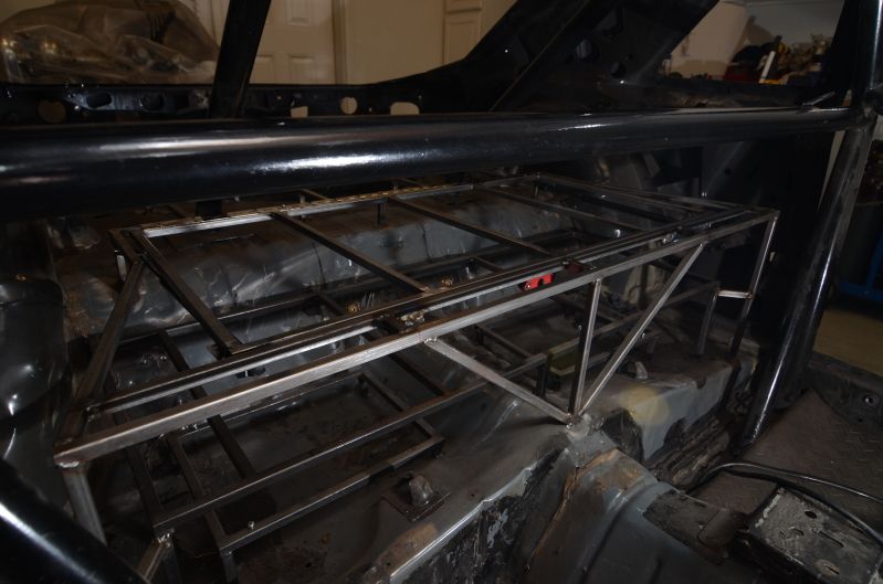
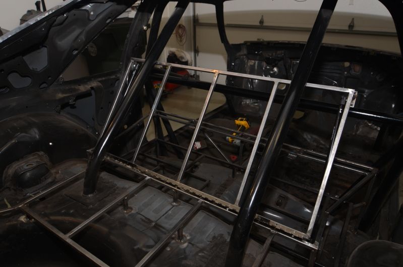
Tacked the front brace in and welded in all the 2" spacers:
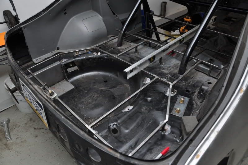
After addng the front pieces. This will cover all the electronics under the rear seat area.
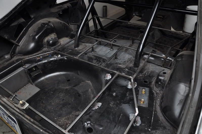
I will also be welding together another frame that will fit inside the outer frame around the rear seat area. It will hinge on a pair of gas struts so I can access the electronics below.
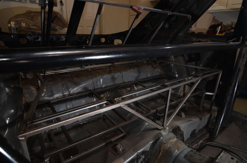
This whole false floor will serve at the mounting point for the carpeted MDF floor that I'll be making when the time comes.
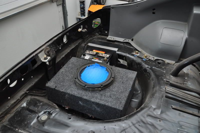
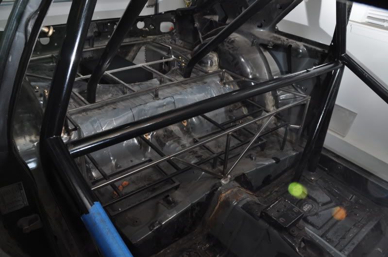
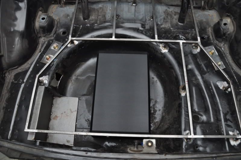
Also got my woofer today. Now I just need to figure out the best way to mount it. It is a downfiring design, so it will mount as shown in the pictures below. I'm thinking about welding in 2 more braces that run front to back and then screwing the ends of the box directly to those braces. I may also use a strap around the middle as an extra way of securing it. I think I'd like to avoid mounting it directly to the spare tire well floor.
Welded together and installed the hinged lid for the false floor area in the back. Came out pretty well.
I wound up using a pair of 20lb struts. It comes up pretty fast, but it will slow down once it has the weight of the MDF and carpet on it. I do need to reposition the lid side of the strut mount. The geometry is a bit off. The lid somewhat floats when it is in the closed position. A small spacer should fix that geometry issue for me.
This is essentially the original write-up that I saw regarding the IRS install: http://www.mouthbreather.net/IRSSWAP.HTML .
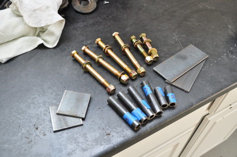
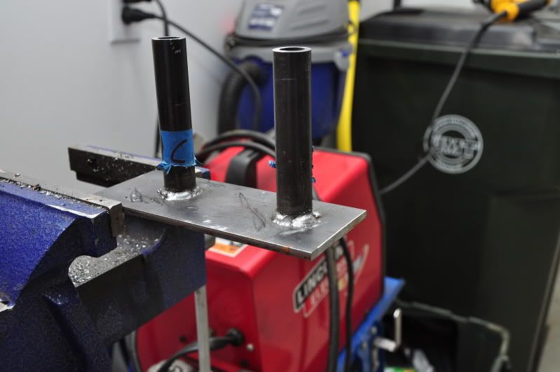
The write-up is very good and well detailed, however, I had one issue with some aspects of the install that I think may have been overlooked. My main concern was that the author made no mention of reinforcing the frame rails that the upper subframe bolts to. The frame rail is shaped like a "U" so the top portion is nothing but some 16ga sheet metal. Installing some oversized washers is not sufficient to prevent collapsing the frame rail, in my opinion. I decided to use some 3/16 steel plate and tube to reinforce the frame rails so there is no chance of any collapse.
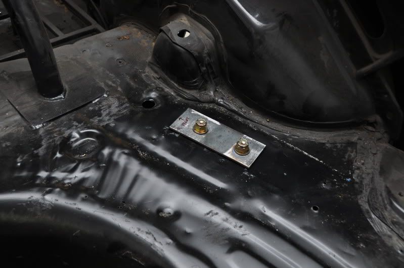
Here's the 1/2" grade 8 bolts as well as the plates and tubes that I cut to size:
I oversized the holes in the floor to give me a little margin of error with lining up the reinforcements:
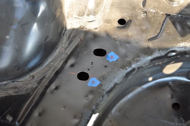
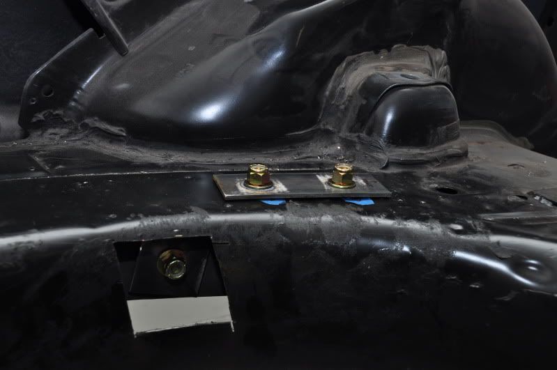
The spare tire well is so close to the driver side frame rail that I had to cut a hole in it to drill through the inner side of the frame rail:
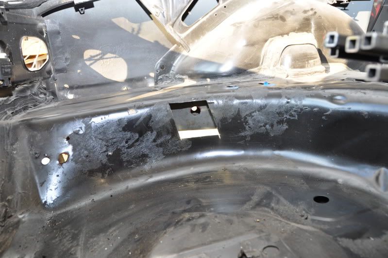
I'll weld it back up and install a grommet in the tire well in case I ever need to access the subframe bolt
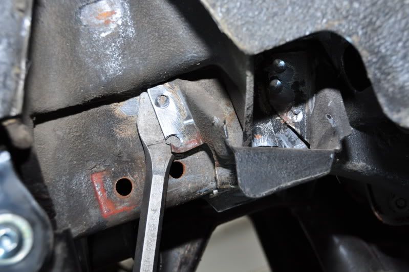
The passenger side needed a little bit of trimming so the subframe mounts would sit flush:
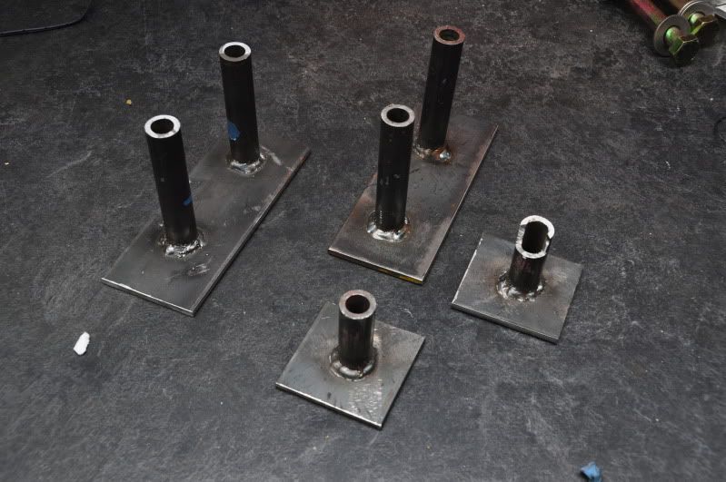
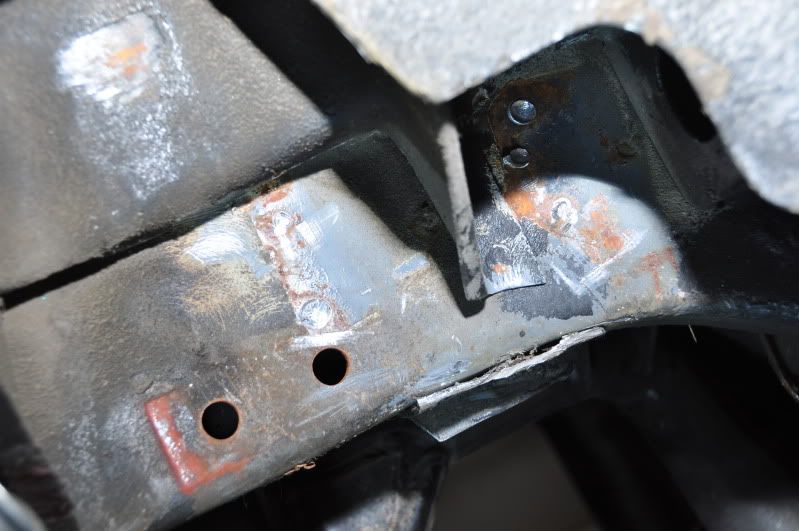
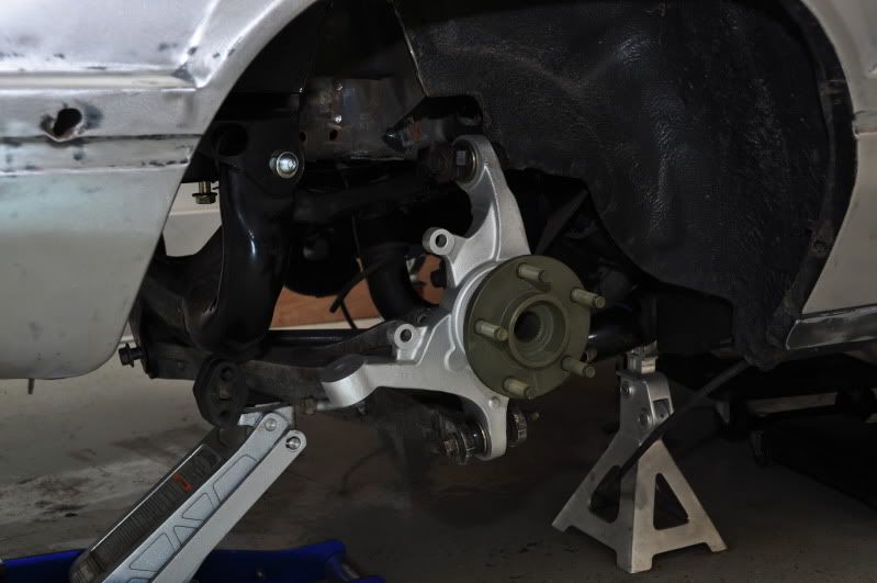
Here are the welded reinforcements. The notch in the one smaller plate is so it clears the welded nut inside the frame rail for the old quad shock mount.
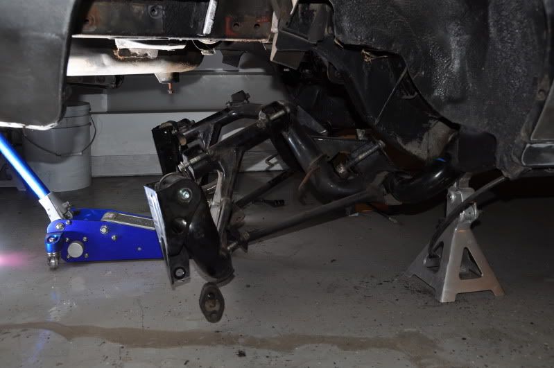
Mocked up in the car:
Removing the old axle snubber so the upper control arm will clear:
Mocked up the passenger side control arms and hub:
And the moment of truth...tire clearance:
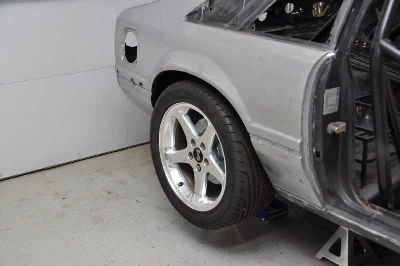
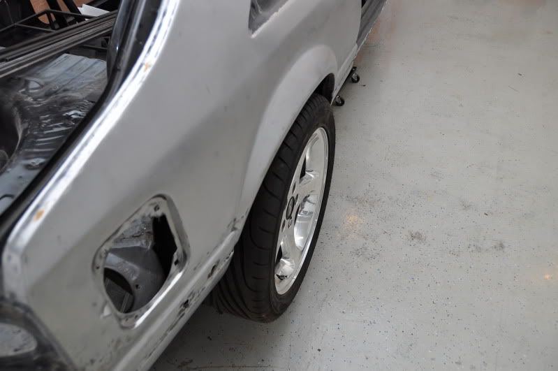
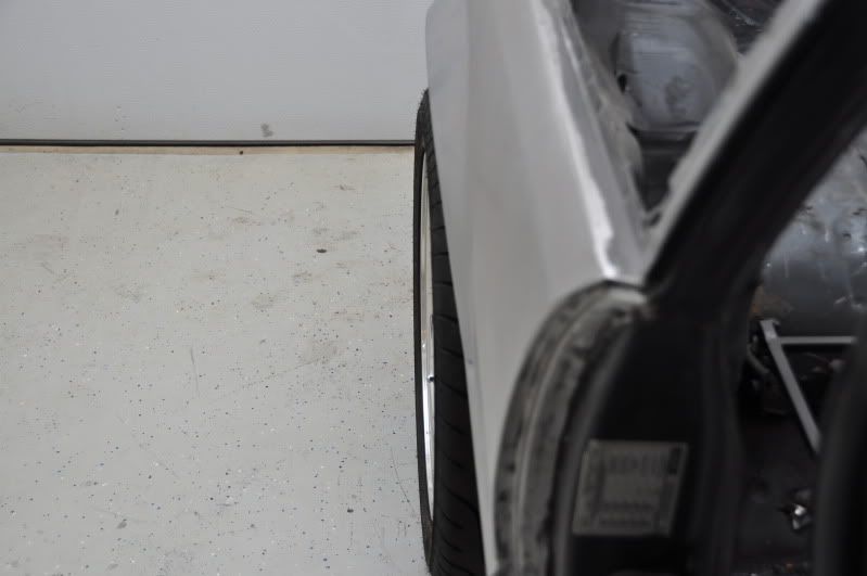
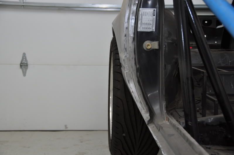
The wheels do stick out a bit, but the camber is not set yet and the car is not sitting under load, so I'm confident the tire/fender clearance will be okay when everything is bolted together and setup properly.
It didn't take long for me to run into my first snag. I temporarily bolted up my MM k-member and mocked up the engine in the car with my HP Performance hotside installed. I going to have to do some trimming on the passenger side for the turbo to fit, which I knew. I'm going to modify the boxed in frame rails to give a little more clearance to the header. Nothing hits on that side though.
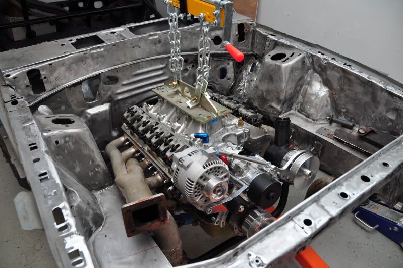
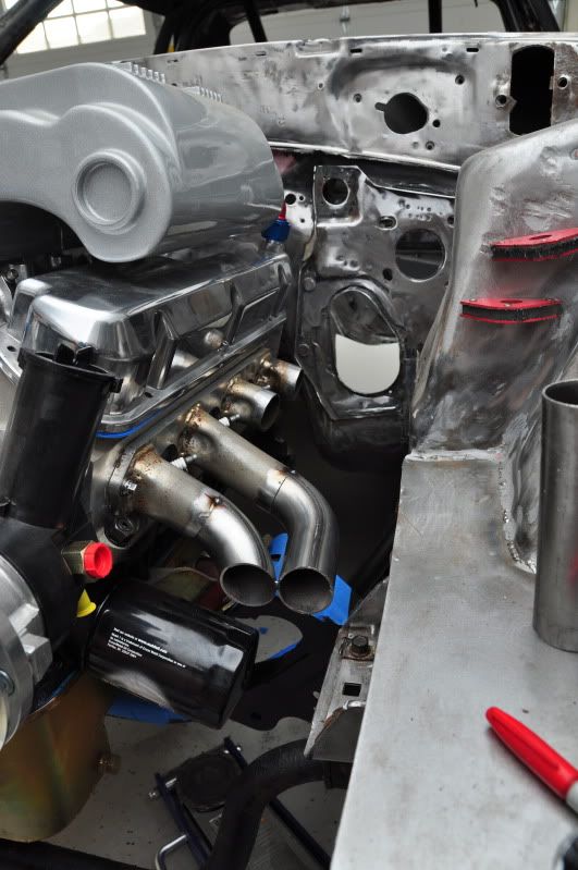
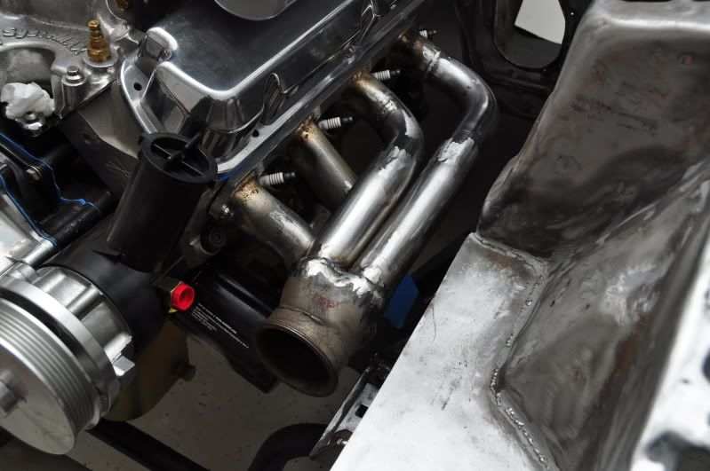
I hit a speed bump when I mounted my driver side header. It wouldn't fit. It's hitting the motor mount on the k-member. And it's not like it almost fits, because the front header bolt is nearly an inch higher than it should be.
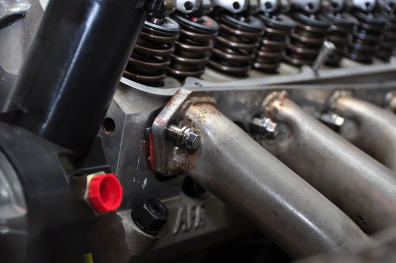
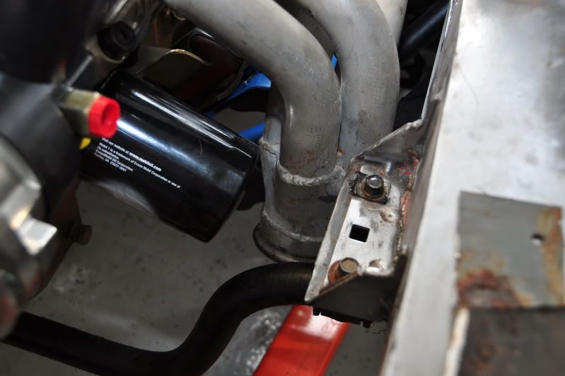
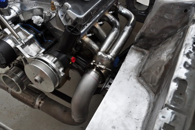
So, the plan is to re-route the driver side header so it meets the crossover pipe near the power steering pump and not between the oil filter and frame rail like it does now. The MM k-member is very beefy and doesn't leave much room in that area. The collector is also very close to the sway bar and I think there may be some clearance issues with that as well. I never understood why HP Performance decided this was the best way to route the driver side of the kit?
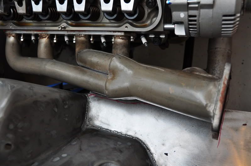
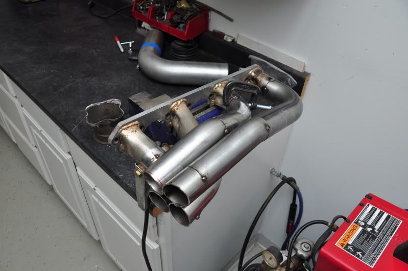
Below is the original configuration. I decided to cut the primaries and reweld new ones in so the collector would sit between the power steering pump and framerail.
All the primaries cut:
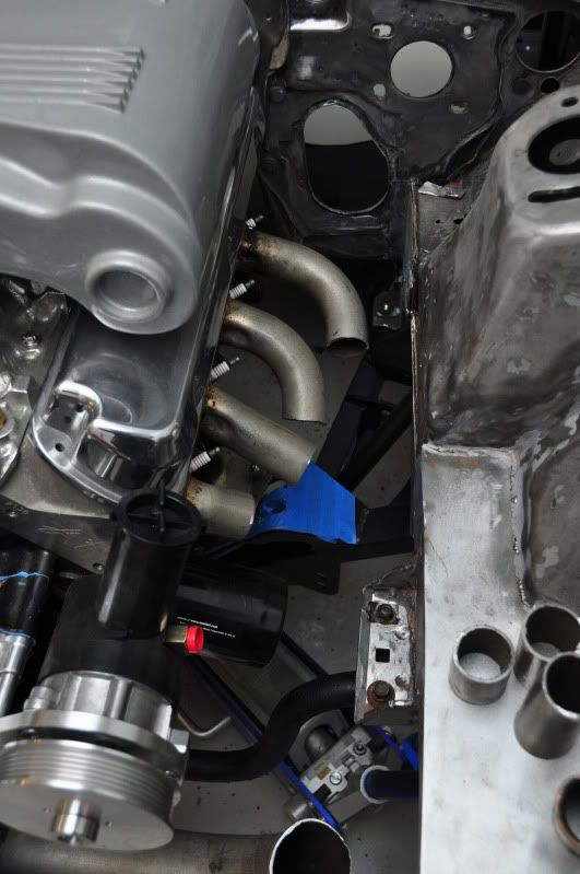
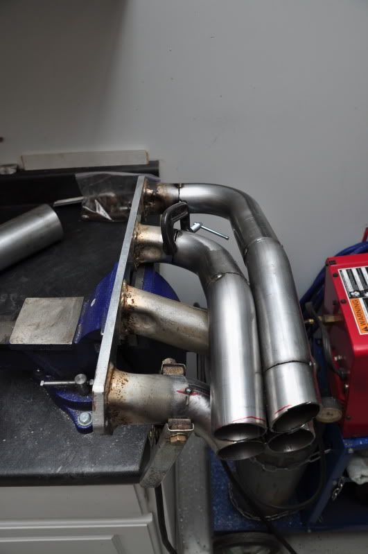
I went over in my head a million times the best way to route the tubes into the collector. After finally figuring it out, I cut the back two again and decided to run the front ones into the bottom of the collector.
With the general collector location determined, I was able to move the header to the bench and tack in the top tubes.
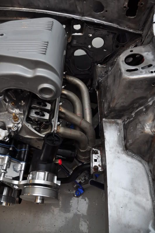
Put it back in the car to make sure I didn't mess anything up.
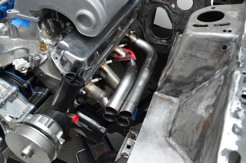
I just need to clean up the tubes where they will enter the collector and then weld everything together. Next will be modifying the crossover to mate up with the new collector location.
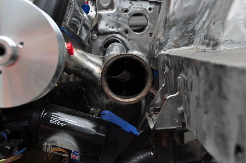
I welded all the tubes together and cut a piece of 16 gauge sheet metal into a 4 point star to fill the gap in the middle of the pipes. I was able to salvage the original collector, which saved me from having to buy a new one.
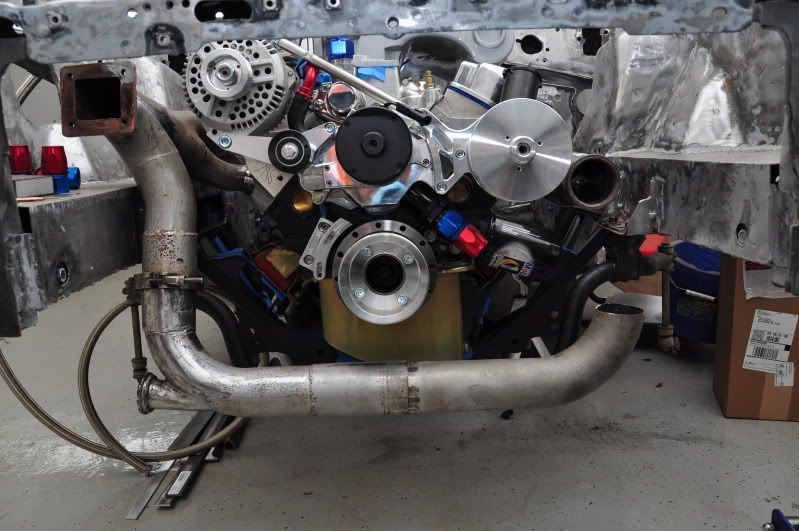
I also decided to install a flex bellow in the crossover tube. They aren't that expensive and if I can help avoid header cracks, why not. Here's the original crossover configuration
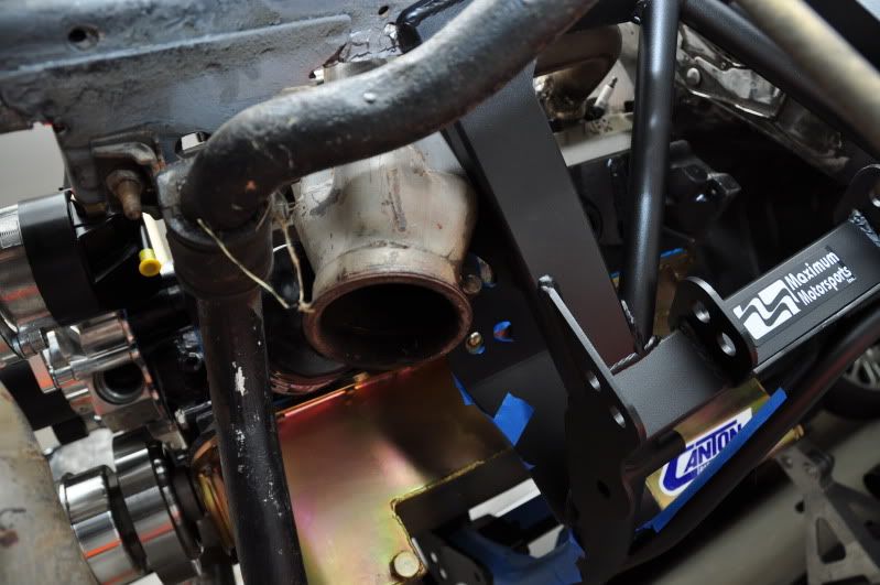
And then after I got done chopping up some pipes:
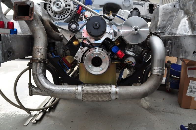
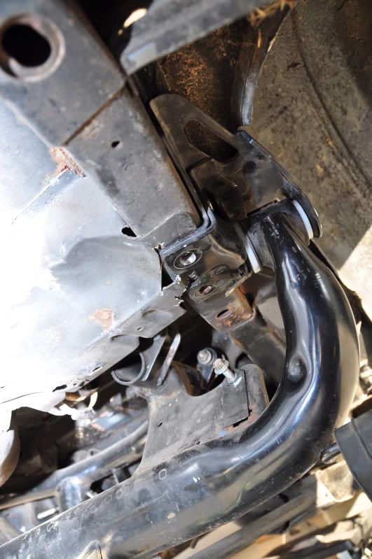
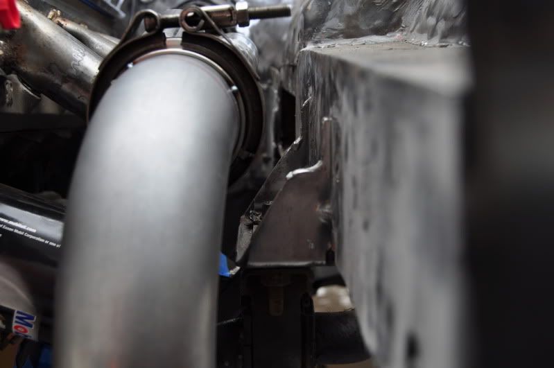
Plenty of clearance to the sway bar mount.
I'm very happy with the way things turned out. I just need to weld the crossover together and then get it ready for coating.
Built the AN lines for my breather setup. I couldn't find a vented catch can that would serve my purpose so I bought an aluminum can from Jegs and modified it to work. I drilled a 1-3/4" hole in the top of the can and had my welder tig a short section of aluminum pipe in the hole. This gave me a neck to mount an air filter to. He also welded three -12AN bungs on the can for me. It came out nice.
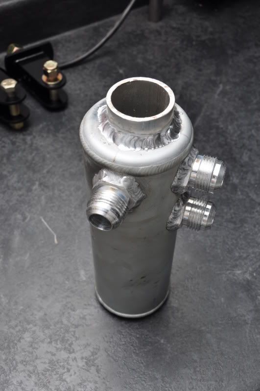
I'll be getting it powder coated at some point.
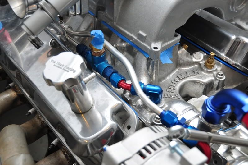
I decided to setup my breather system a little different than most. I'm not going to be using a PCV system so I had a -12 bung welded to the PCV hole in the lower intake in addition to the typical bungs on the valve covers. My theory is that the lifter valley is the best source to evacuate crankcase pressure. This way, the pressure does not need to find it's all the way to the back of the heads and through the valve covers. Most of the pressure will evacuate itself through the lower intake first, and then the rest can find its way to the valve covers. Here's what it all looks like mocked up.
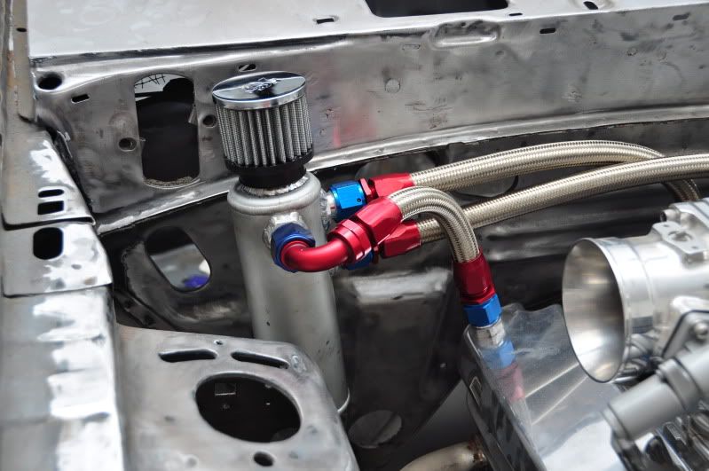
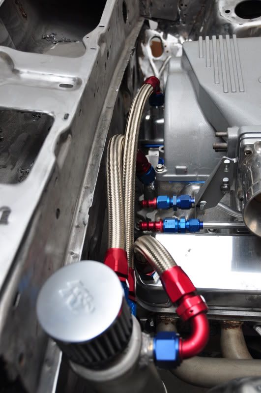
Yes, the can is crooked and a little high. Its not bolted to the firewall yet. I need to get the right size bolts and some spacers to bolt it up. I figured this will be a good spot for the can so I don't have AN lines strung all over the engine bay.
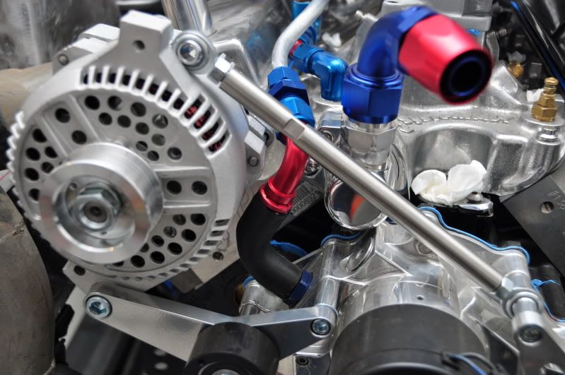
I also stumbled upon a thread on corral where a guy used aluminum tubing and AN fittings to replace his steel heater tubes. I like the way it looked so I duplicated it. I may need to modify it a bit for the water line feed and return to the turbo.