
You are using an out of date browser. It may not display this or other websites correctly.
You should upgrade or use an alternative browser.
You should upgrade or use an alternative browser.
Resource icon
1988 Mustang GT Restoration/Modification
- Author RacEoHolic330
- Creation date
BBRC 14 gallon aluminum fuel tank
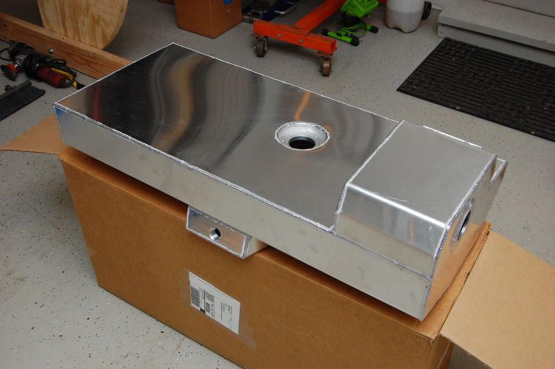
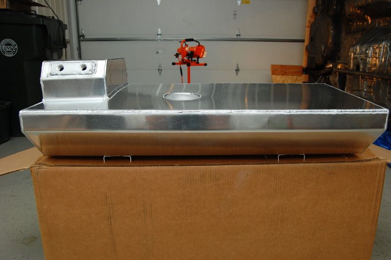
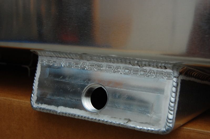
I had the tank powder coated in the black. I was originally going to go silver, but decided I would like the black better because it will not stand out as much with the Cobra rear bumper. I'll have a black fitting and black braided line coming out of the sump. Trying to keep things stealth here.
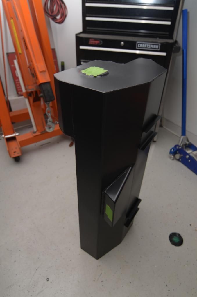
The straps are still bare aluminum. I may have them coated silver for contrast. Still undecided on that yet.
Fuel pump setup.
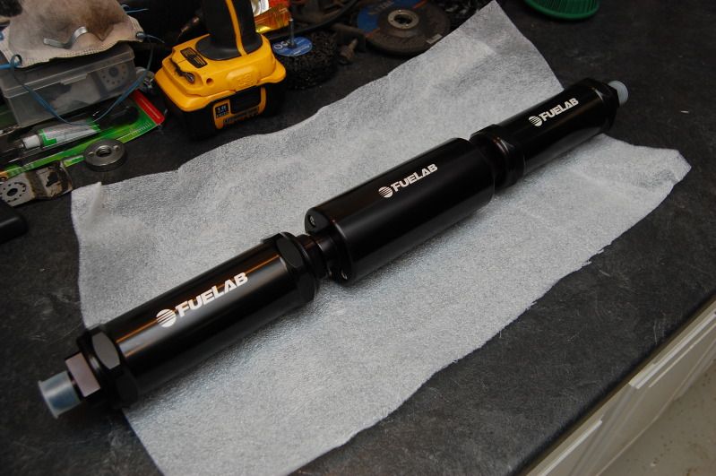
Consists of a pre-pump filter, 1300hp pump, and post-pump filter with a built-in check valve. The damn filters are longer than I thought.
I also got an electronic fuel pressure regulator from Fuelab.
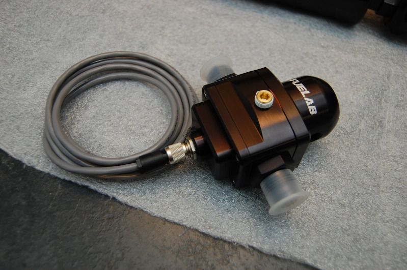
The regulator also doubles as a pump controller. It controls voltage to the pump based on engine demand. These big pumps must run at reduced voltage when just cruising around or else they will burn up. The regulator does the job that an external controller would. I'm pretty sure Fuelab is the only company with technology like this. Pretty cool stuff.
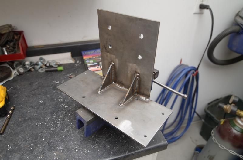
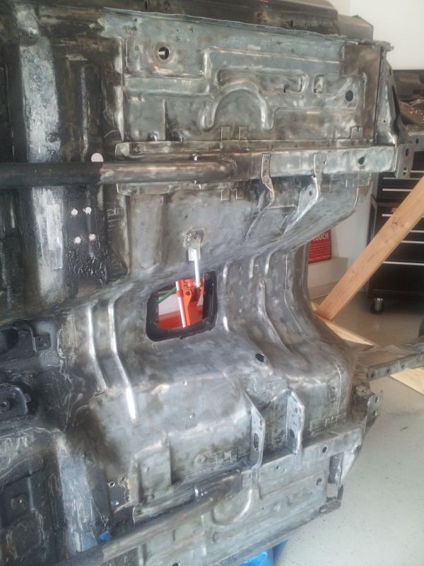
Fuel pump bracket.
Pump mounted
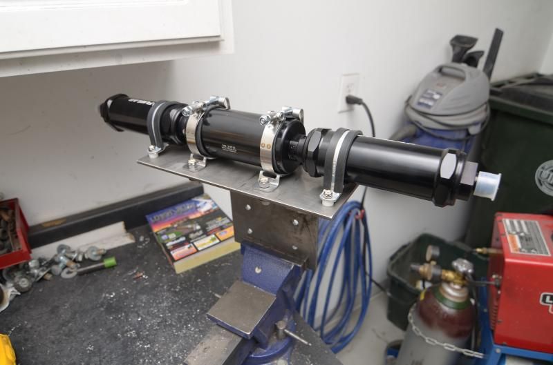
I'm not drilling the holes in the body until I know exactly where I want to mount the bracket, but this kind of shows how it will all be mounted.
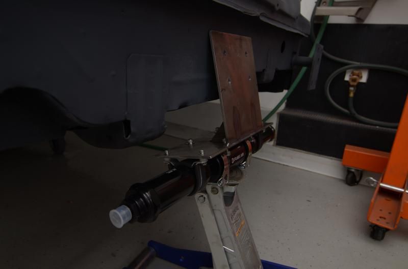
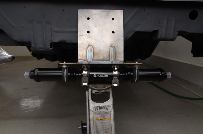
Fuelab says that the pump should be mounted as low as possible, but it's not the end of the world if it's a few inches above the sump outlet on the tank. I 'd prefer to have the pump hidden behind my Cobra bumper, but I'll live if it shows a little. I'm trying to keep the car somewhat sleeperish, and a huge 1300hp pump sicking out the back doesn't scream sleeper. Then again, neither does the sumped tank or exposed braided fuel line out the back.
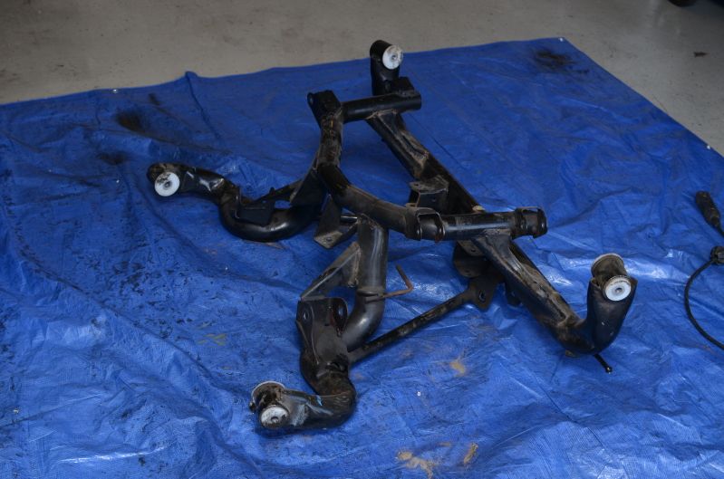
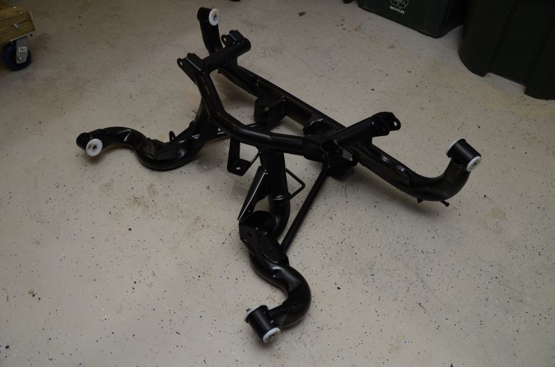
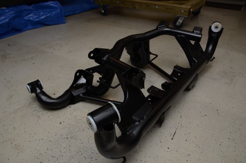
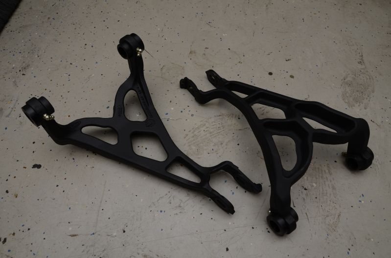
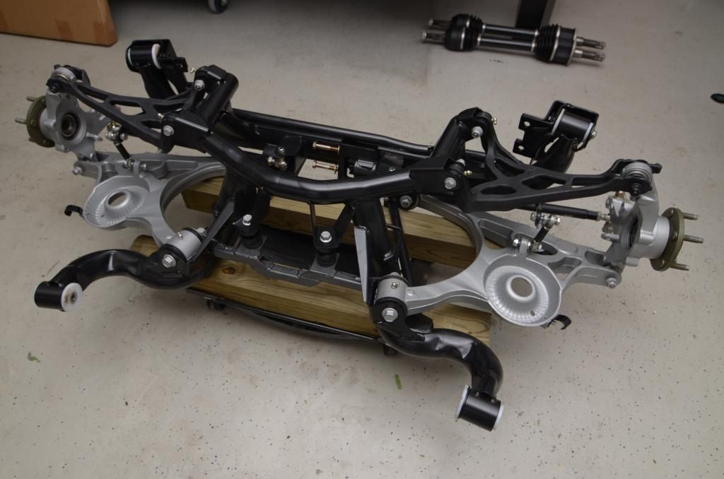
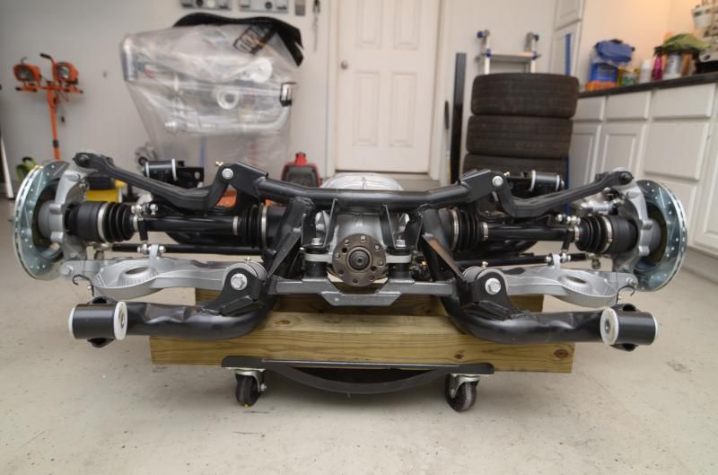
Below is the restoration of the IRS subframe and parts. I would have liked to just have everything poweder coated, but all the IRS parts already have the Full-Tilt bushings installed, and they are a major PITA to get out and put back in, so chassis paint will have to do!
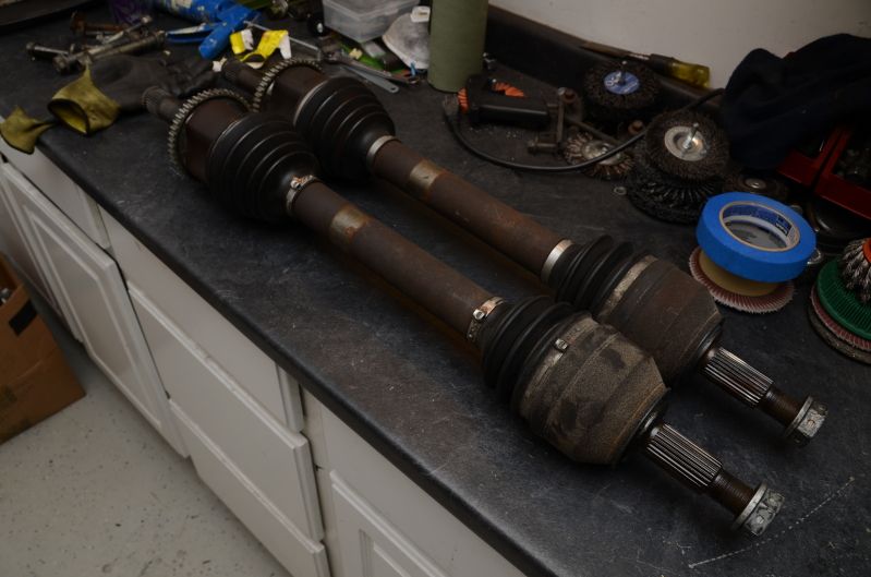
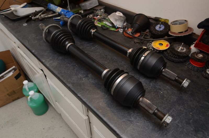
Cleaned up the IRS half shafts.
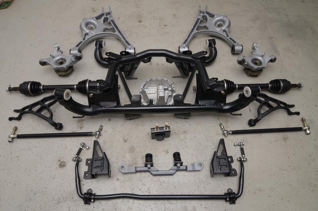
Here's all the IRS parts ready to go...
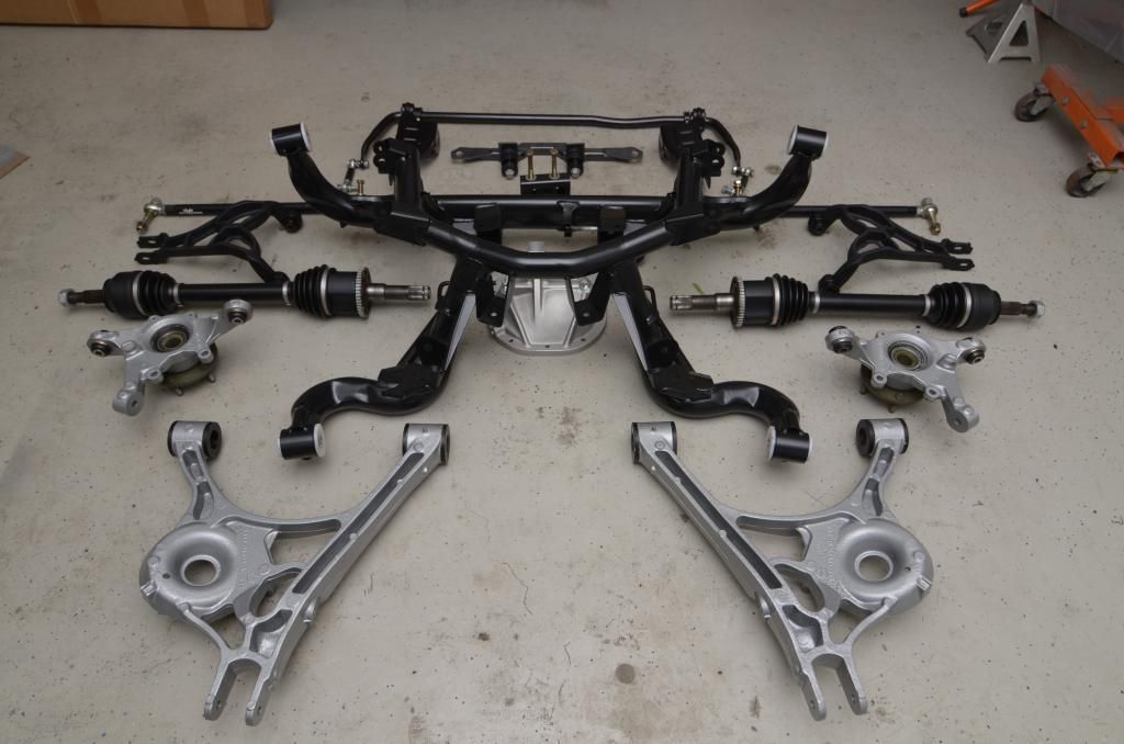
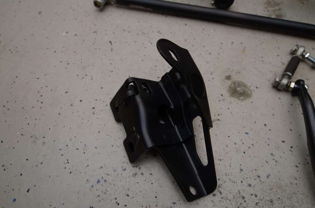
The upper subframe brackets were powder coated in a semi-gloss black.
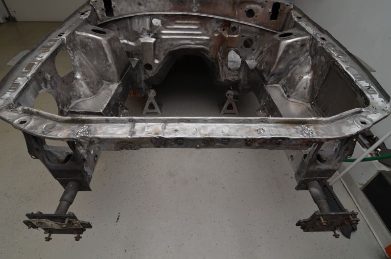
One thing I forgot to do when the car was on its side was to expand the lower torque boxes. When I mocked up the IRS, it was a real PITA to get the lower subframe mounts to squeeze into the torque box buckets, and that was just with a bare subframe. It will be much more difficult with a fully loaded IRS.
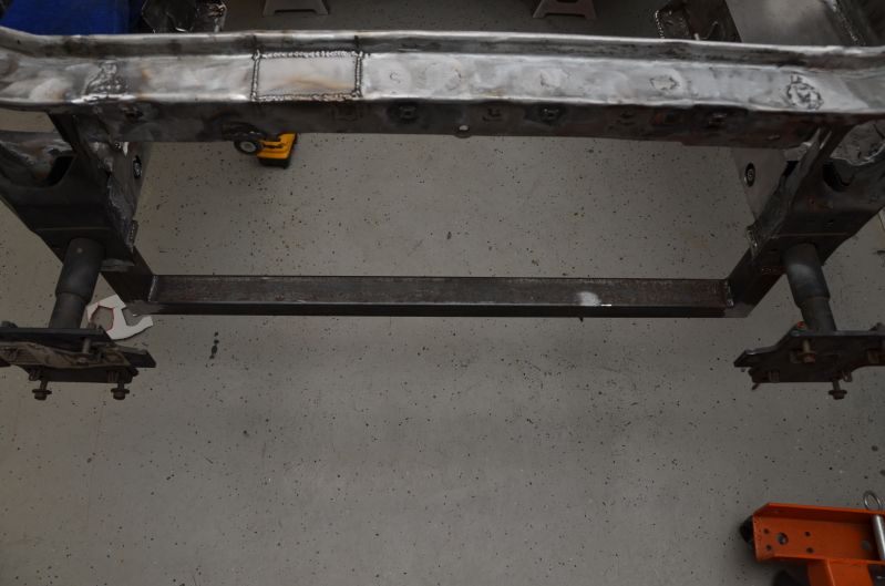
Took a 1/2" rod, some fender washers, and two nuts and expanded the heck out of them. The black marks on the threaded rod are the original position.
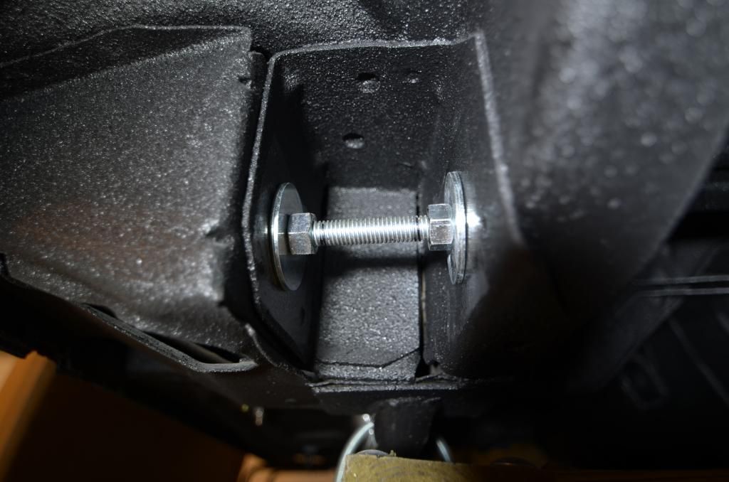
I should have bought enough hardware to do both sides at the same time, but I'm not that smart.
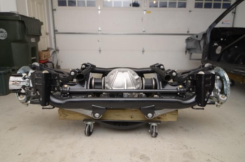
I did manage to get the IRS back together save the differential. Didn't torque everything down yet, but at least there aren't a dozen parts laying all over my garage.
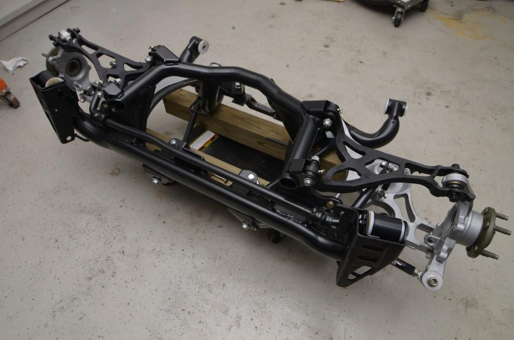
Greased all the fittings and torqued everything together. She's all ready to go now.
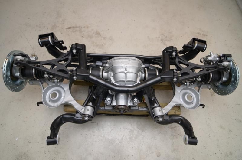
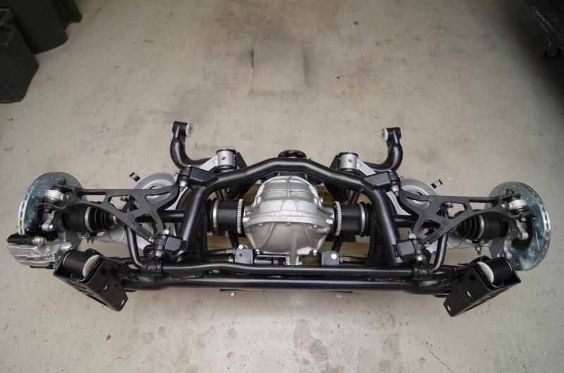
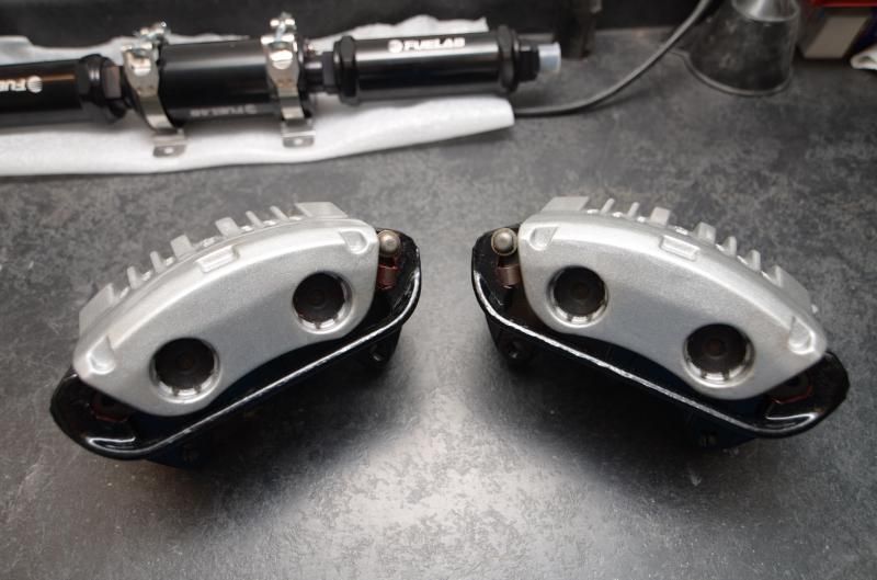
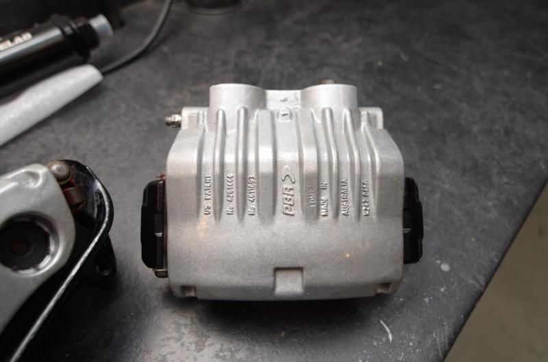
Yes, there is only one caliper mounted for now. I made the foolish mistake of ordering 2 left hand calipers online. I unfortunately did not realize I did that until I went to paint them. The unfortunate part is that I used G2 caliper paint which is a 2-part system. I already mixed in the reactor, and then noticed I screwed up with the calipers. It wasn't a big deal to return the caliper and get the proper one, but now I have to order another caliper paint kit. Oh well. The calipers did turn out nice though. The mounting brackets are powder coated.
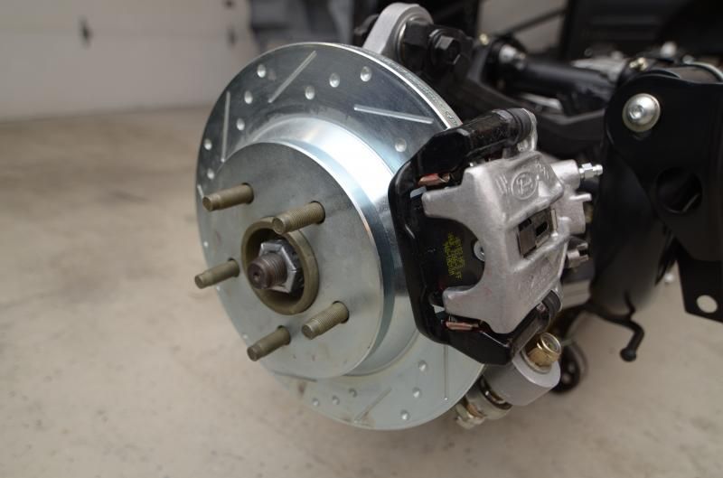
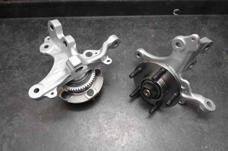
The front calipers and spindles were also painted in the same silver.

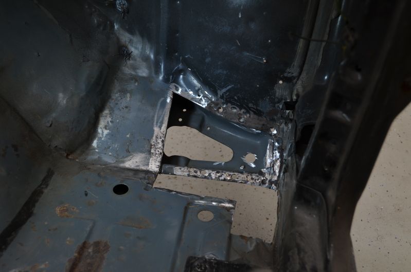
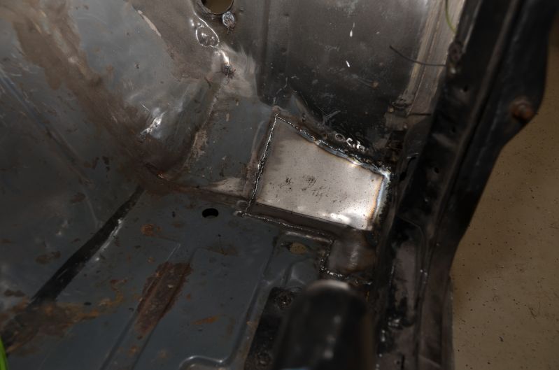
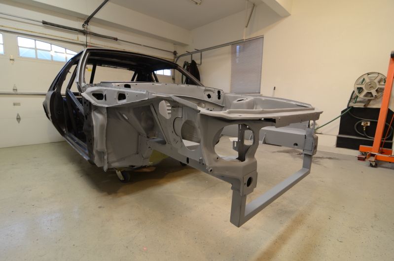
First thing I needed to do was repair the footwell damage. I cut out all the rust-infected area.
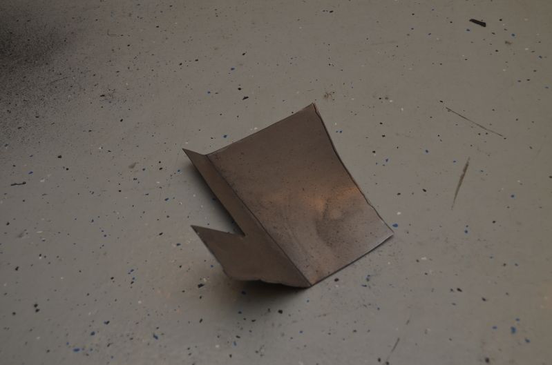
Made myself a new piece.
And welded her in.
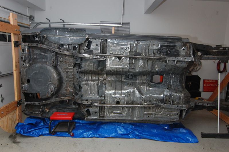
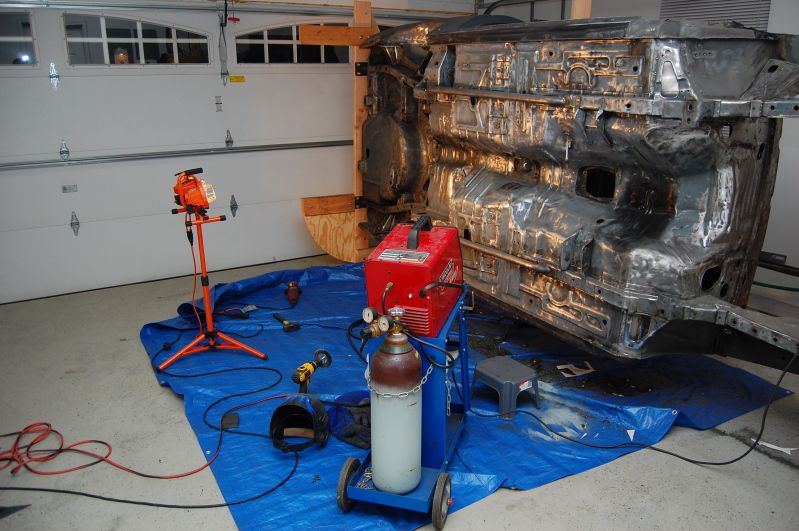
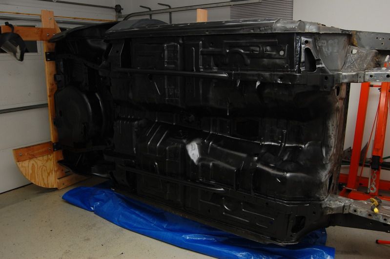
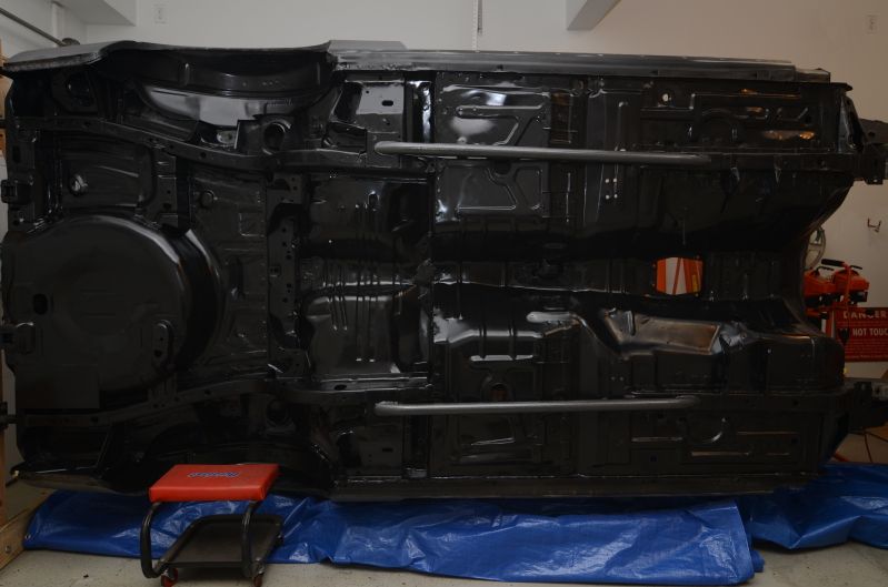
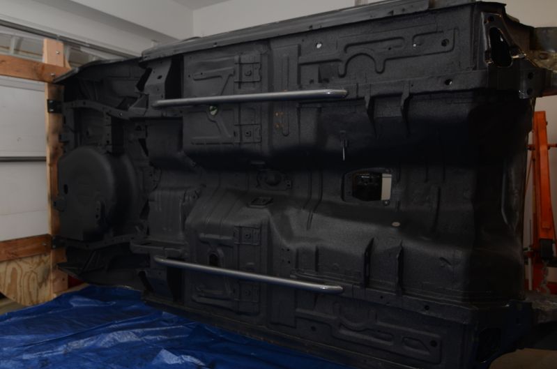
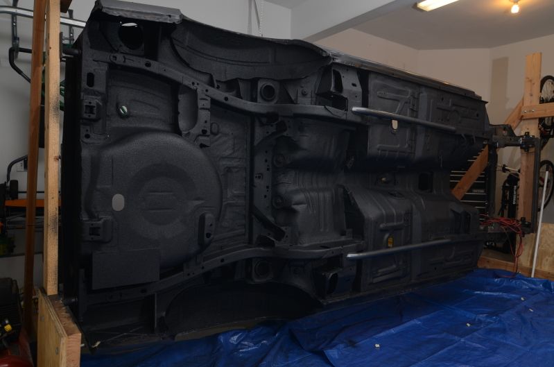
Built myself a little rotisserie to make my life 100x easier. Beats the hell out of laying on my back and scrubbing the bottom of the car.
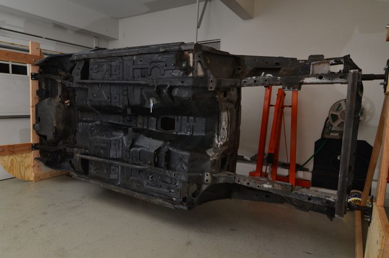
Credit for the rotisserie design goes to a Corral member. I stumbled upon a thread where a guy posted plans and pictures of his. I modified it a bit to work for my needs. I'll have to find the thread again.
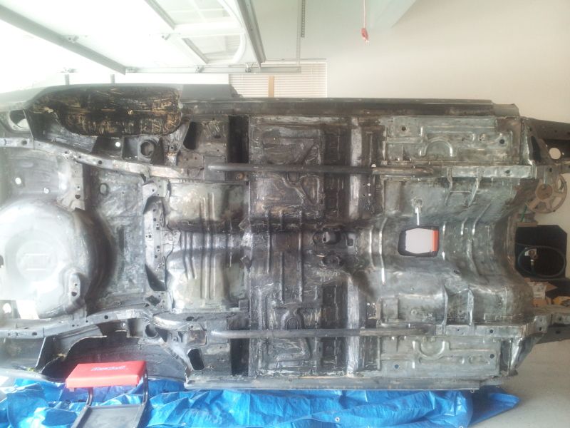
Although I can now work on the underside comfortably, it's still going to be a good amount of work to get everything clean up and pretty.
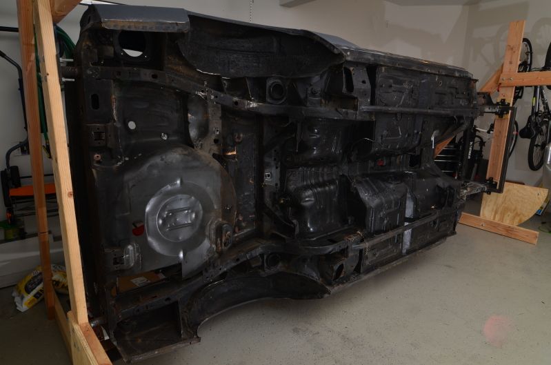
Rubberized undercoating SUCKS. There really is no easy way to remove this gunk. I started doing it chemically, and then realized all that does is make it a tacky mess. Wire wheels get gunked up within minutes. I finally resorted to using a oscillating tool with a scraper blade on the end to scrape up the majority of the mess. It's making quick work, in my opinion. I'll follow that up with a knotted high-speed wire wheel and then a paint removing disc. Should hopefully get the job done.
I also bought some POR 15 Marine Clean and Prep and Ready to give the underside a final cleaning before paint.
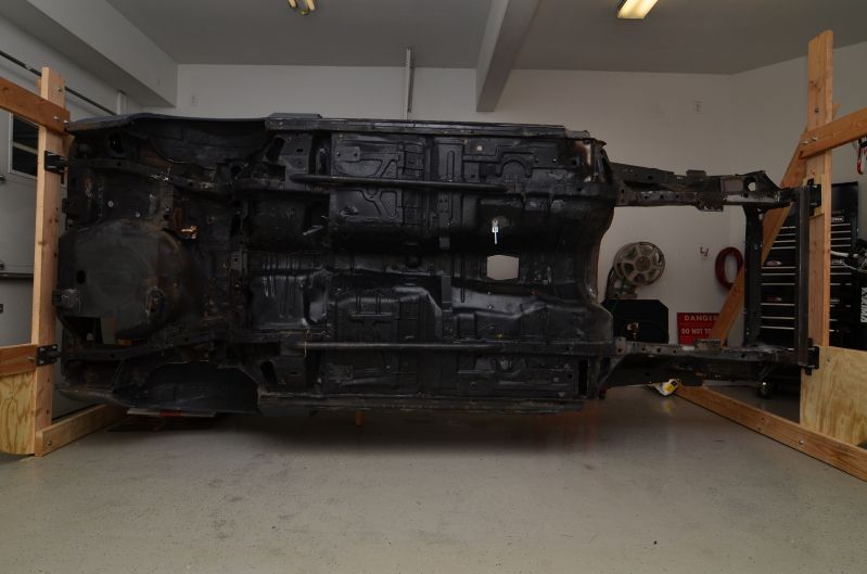
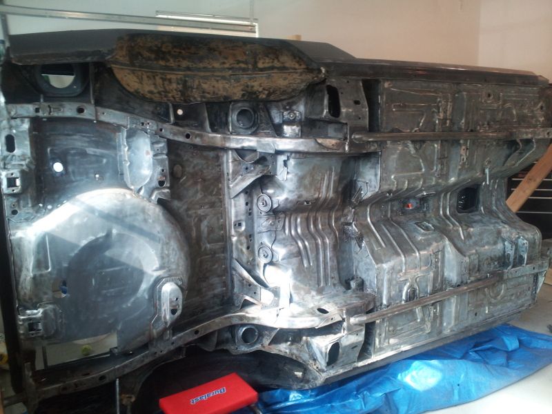
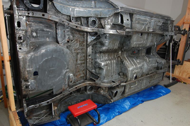
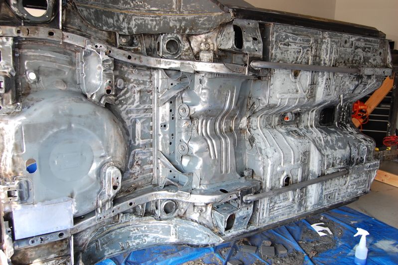
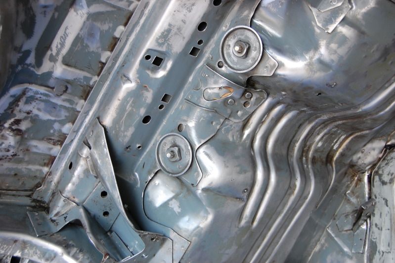
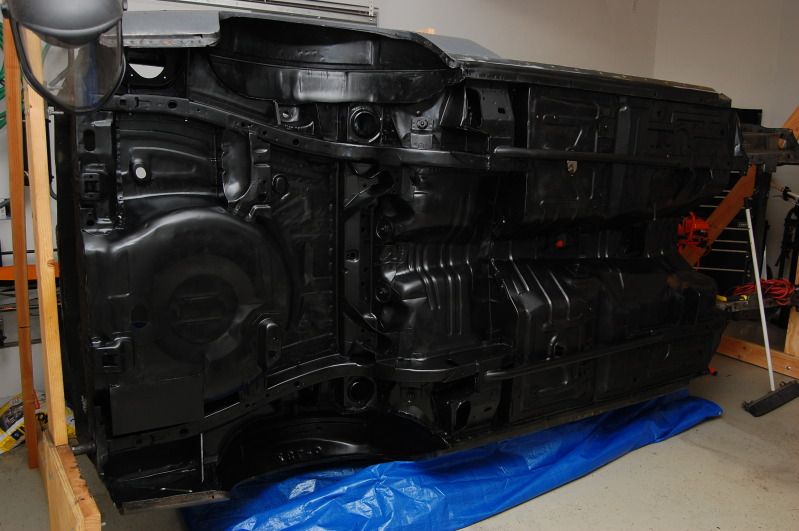
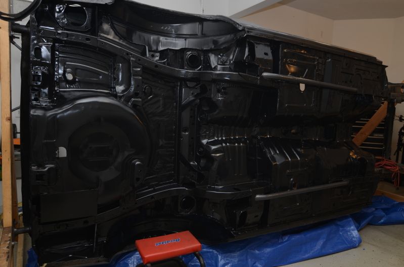
Have about 95% of the junk underneath all removed. Just need to go over the hard to reach areas by hand because I couldn't get the wire wheel or scraper in some areas. Coming along though!
The front portion is after scraping away the undercoating and hitting it with the knotted wire wheel.
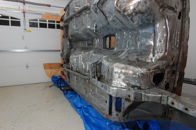
Repeat until the whole underside looked like that...
Once I get the rest of the little nooks and crannies (and wheel wells), I'll wash everything down with a solvent and then hit it with a metal prep and she will be ready for primer, paint, and then eventually bedliner.
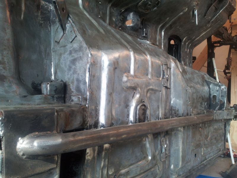
I have some minor rust repair and welding to do, then I can clean everything down and get to spraying.
Welded in my battery tray.
Underside is just about all ready for paint. Just need hit it with compressed air and then wash everything down with solvent and prep chemicals.
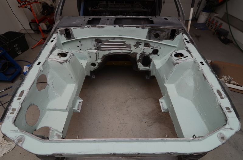
Scuffed, washed, and prepped. All ready for some black primer. Because I was going the bedliner route, I didn't bother to get the underside 100% flawless. The bedliner will be very forgiving and will cover up my laziness.
And finally, one coat of primer. Hopefully shooting the satin topcoat tomorrow as well.
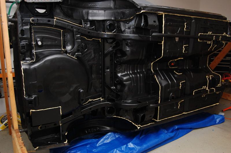
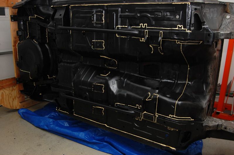
Seam sealer!
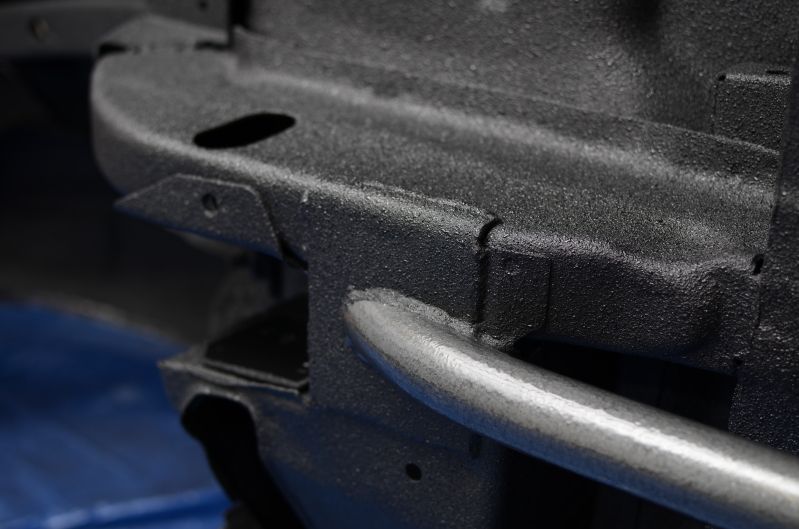
Shot the top coat this weekend. Nothing but some simple Eastwood Chassis Black paint. I also hit the subframe connectors with some hammered texture paint. That will be the same finish on the roll bar inside the car.
Well, here she is. Underside is officially complete.
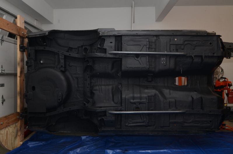
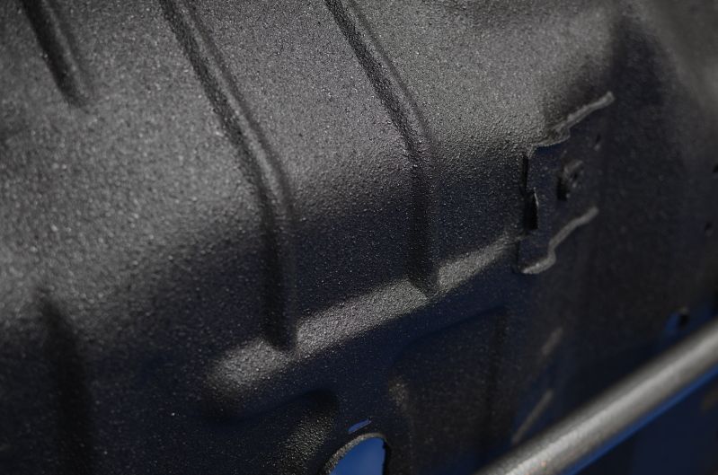
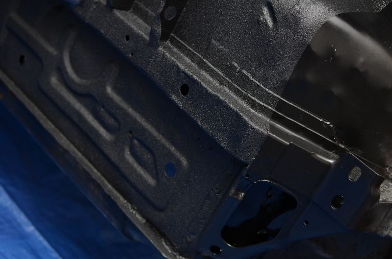
I am honestly VERY happy with the results. The pictures don't even do it justice.
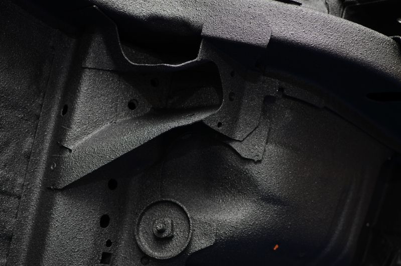
The spec sheet said to shoot it between 40-70psi. I knew that more pressure would shoot a finer mist, so I shot it at 60psi. I also kept the gun at least 12" away from the surface. On the second coat, I kept it probably 20" away. This created a final look that almost resembles the look of 80 grit sandpaper. The wheel wells have 3 decently heavy coats on them, but keeping the gun far away kept that sandpaper look even with the heavy coats. I didn't want that 'chunky' bedliner look, and I'm glad I was able to avoid it coming out heavy.
It also hides just about all the body imperfections on the bottom as well. I really couldn't be happier. If anyone is thinking about using Raptor Liner, do it. It's so easy to apply, and for a total cost of $120 including the gun, you can't beat the price. I still have one bottle left over out of the 4 it came with.
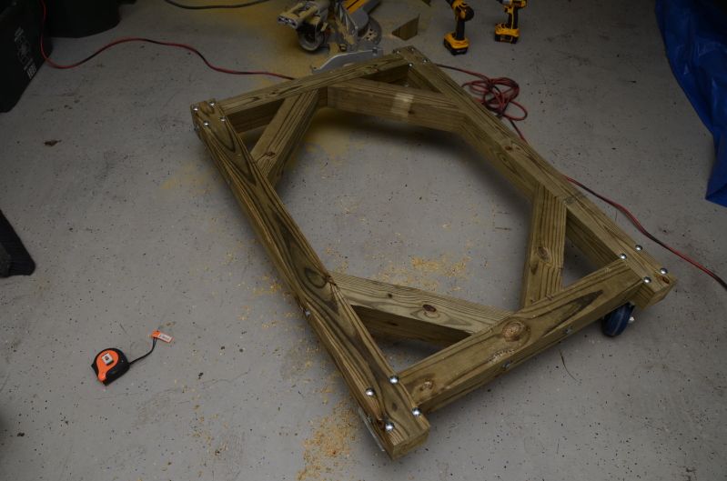
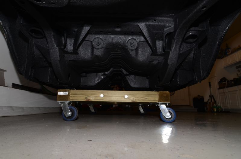
Built myself a handy dandy little dolly tonight to be able to get the shell onto a flatbed and also so the painter can move the car around the shop. Nothing more than a couple of 4x4's and some heavy duty castors. Should be good to hold over 1600 lbs.
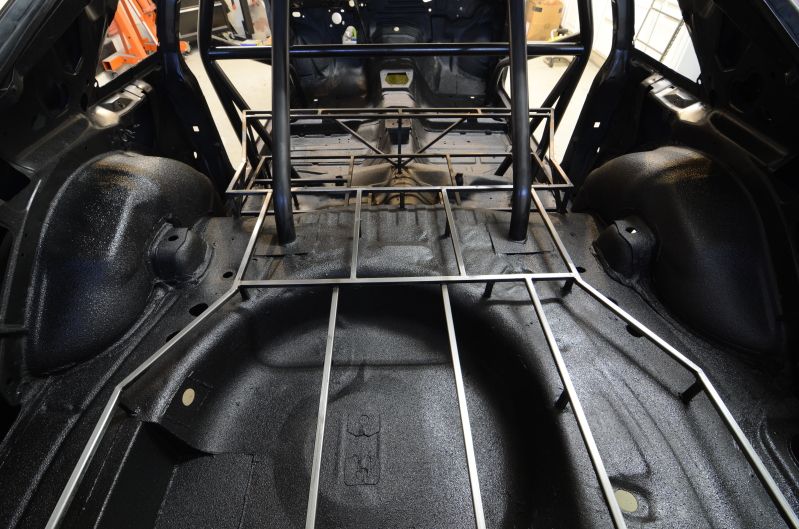
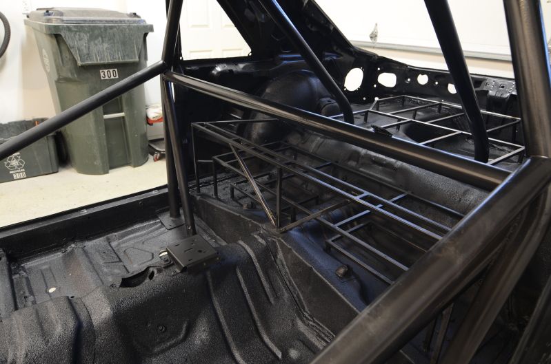
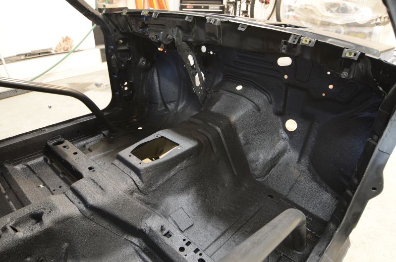
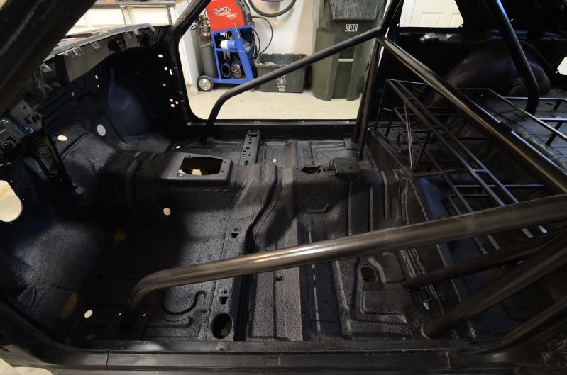
Shot the interior with some chassis paint. Will be topcoating it with Raptor liner.
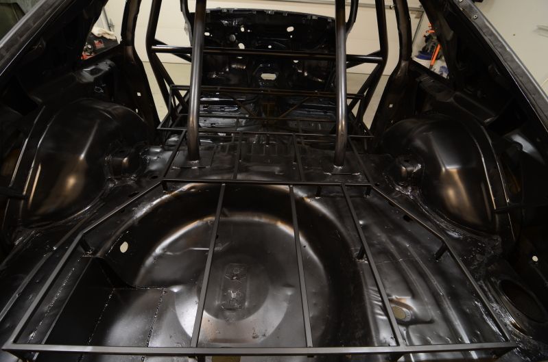
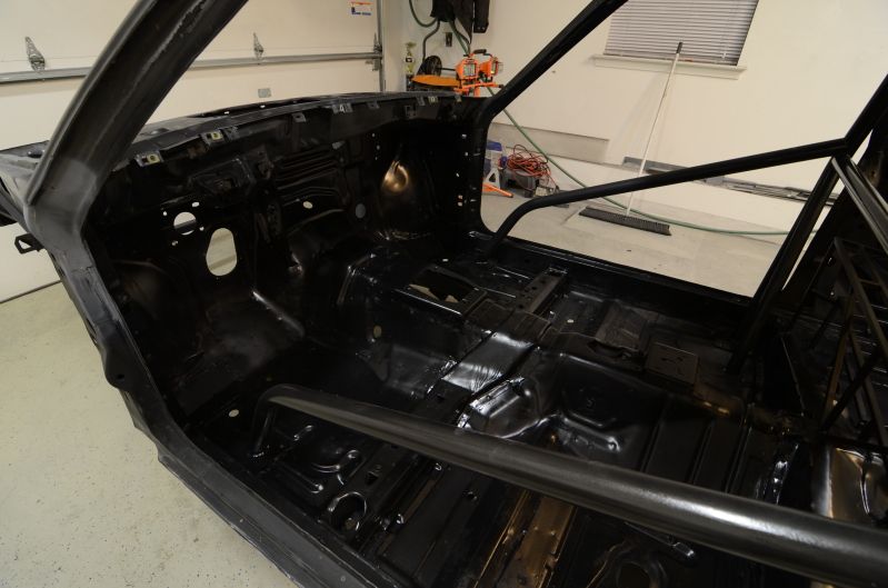
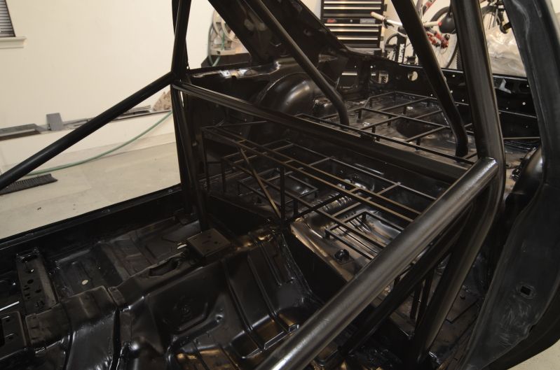
Raptor liner top coat.
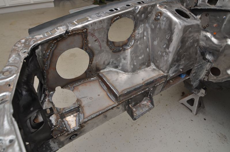
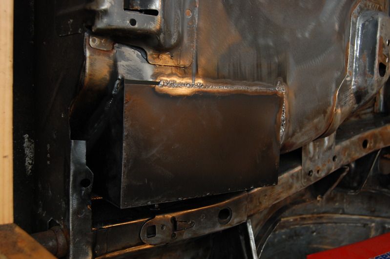
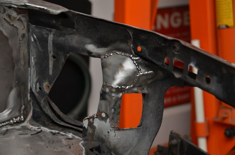
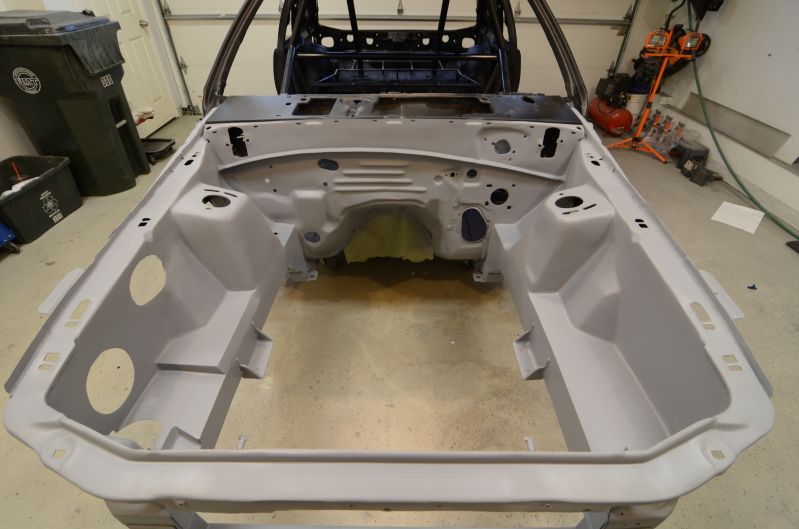
So after I had already welded the large holes near the brake booster location, I decided that I didn't like how that area looked. Cut out a piece of sheet metal to cover everything up.
Cleaned up the brake booster mounting reinforcement plate
Cut a crude template
Made the crude template better
Transferred to sheet metal
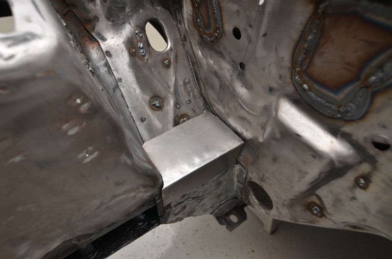
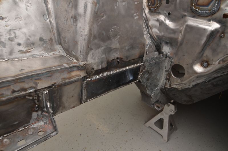
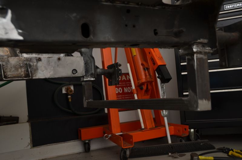
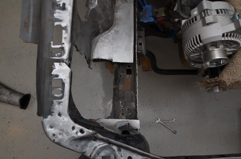
My solution to the rusted out k-member supports was to clean out the framerail, apply anti-rust paint, make new supports, weld them in, paint again, and then weld a new, stronger piece of sheet metal in to reinforce the framerail.
New supports
After some painting, welding, and more painting
Driver side
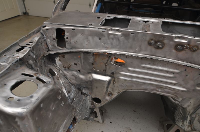
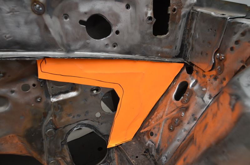
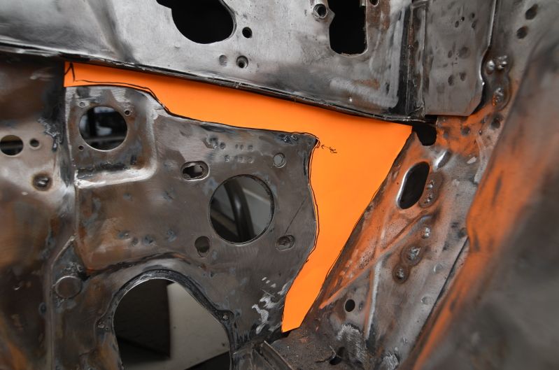
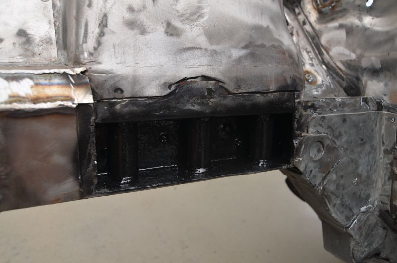
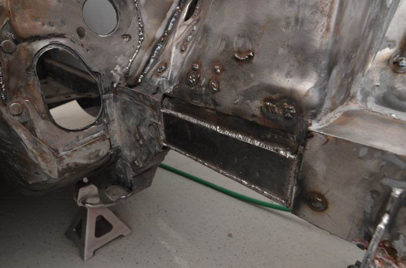
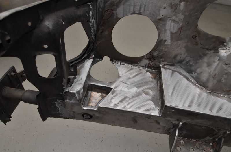
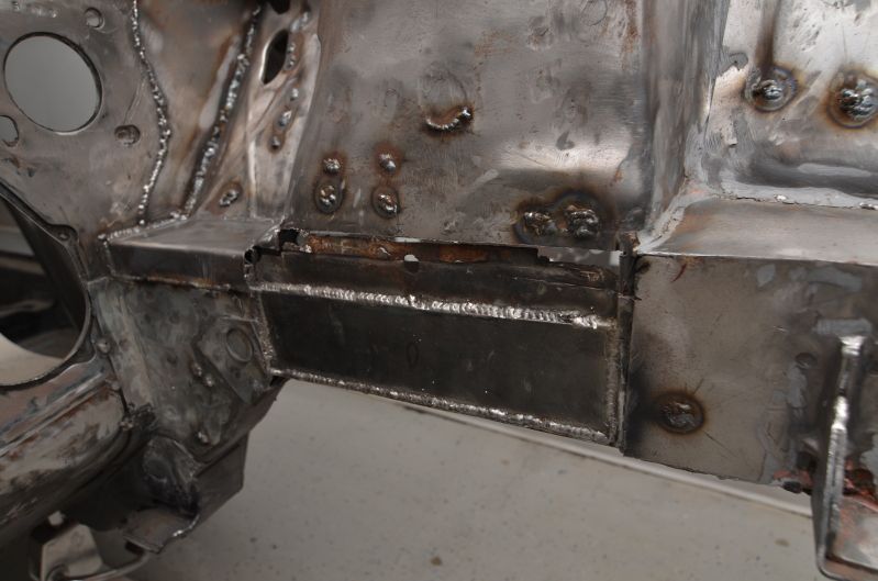
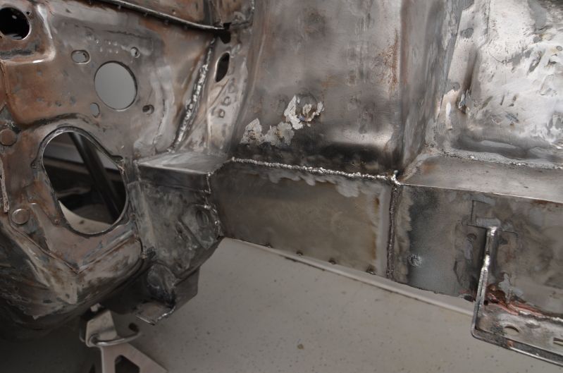
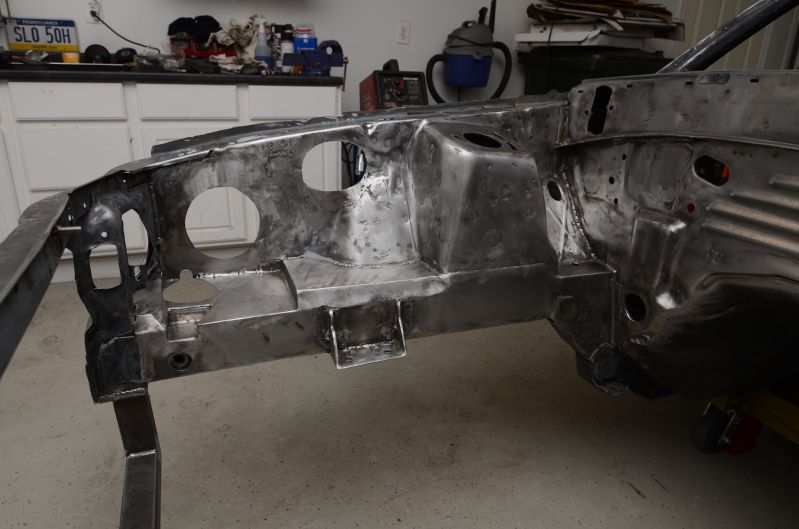
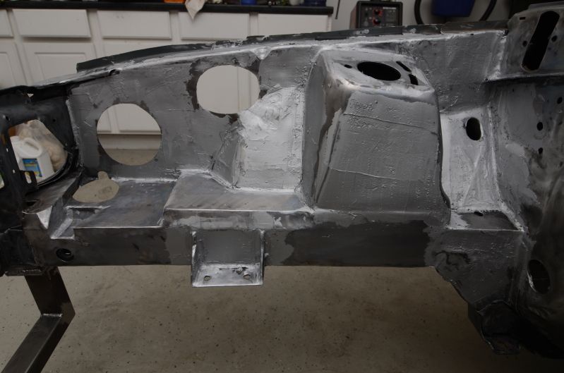
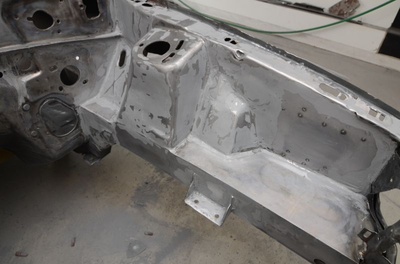
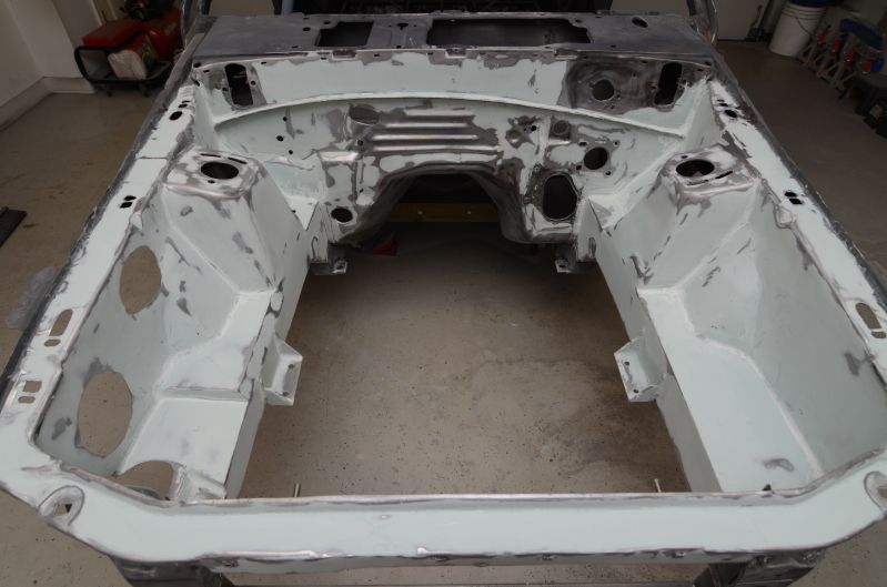
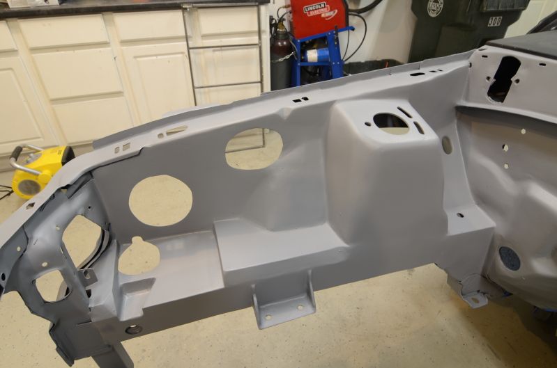
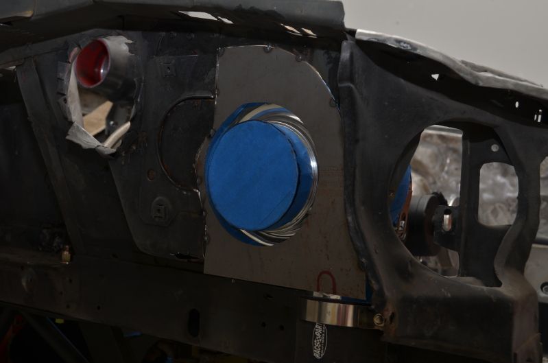
I figured that a good portion of the rust was to blame on the holes in the framerail directly under the strut tower. This area is constantly exposed to the elements while driving, so I decided to weld those holes up to eliminated the possibility of water sitting in that area anymore.
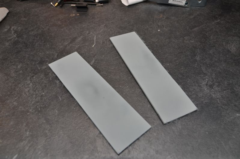
Here are the new pieces of sheet metal that I'll be welding in to box the framerail back together.
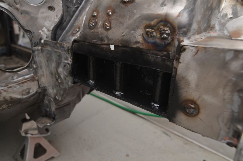
I also cut out and mocked up the passenger side sheet metal behind the strut tower. Didn't get around to welding it in yet though.
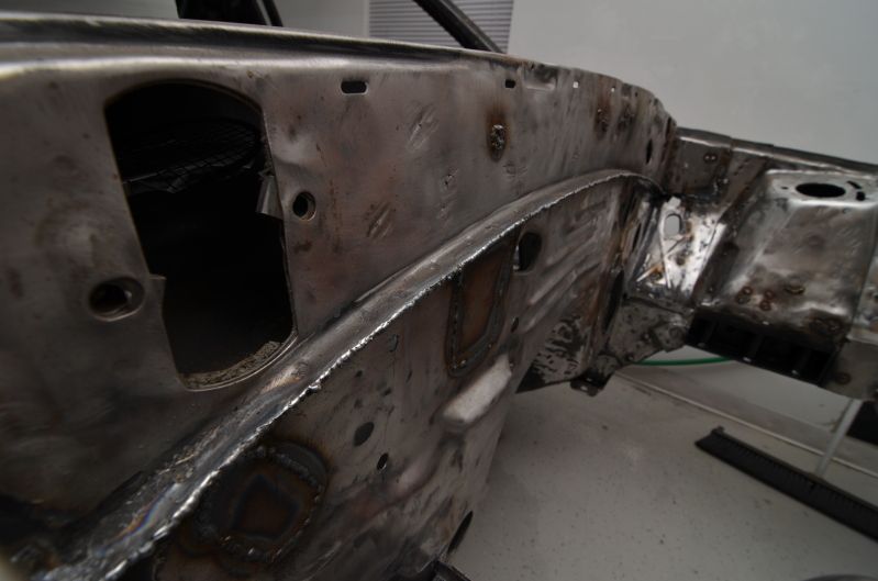
The last thing tonight was welding the pinch weld along the firewall. I had already trimmed it back to make it look a little better, but the two pieces of sheet metal were still visible and that was ****ing me off, so I welded it up. It will be grinded down nicely and be given somewhat of a rounded bullnose edge.
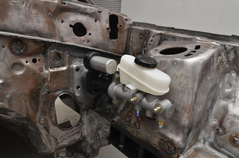
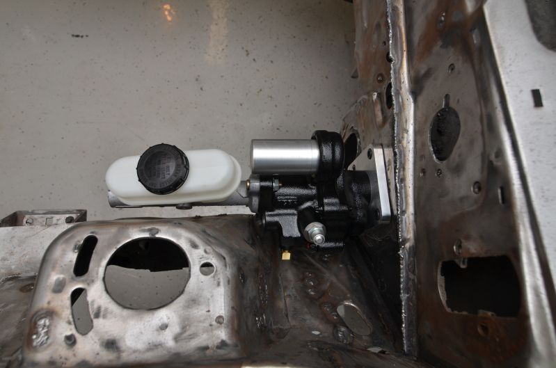
Mocked up the hydroboost unit and MC to make sure everything cleared. All is well in that department. Shouldn't have any issues with running the lines. I also won't be needing the stock-style prop valve anymore, so I will just need to find a spot to mount the Wilwood prop valve for the rear bias.
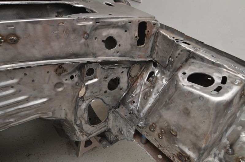
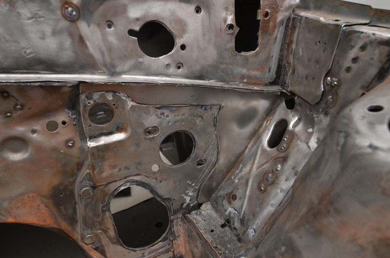
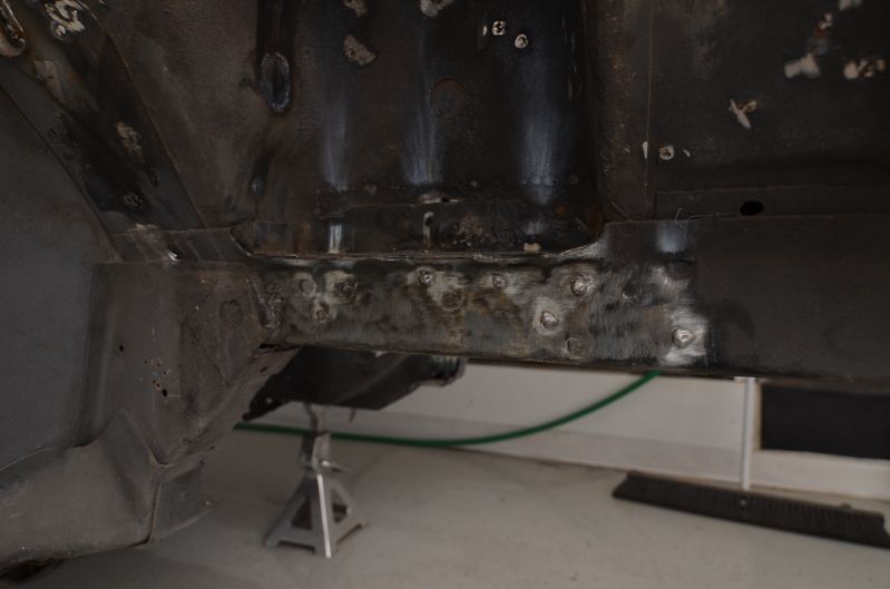
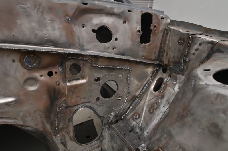
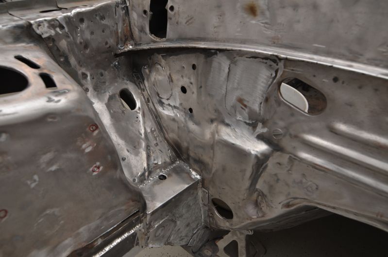
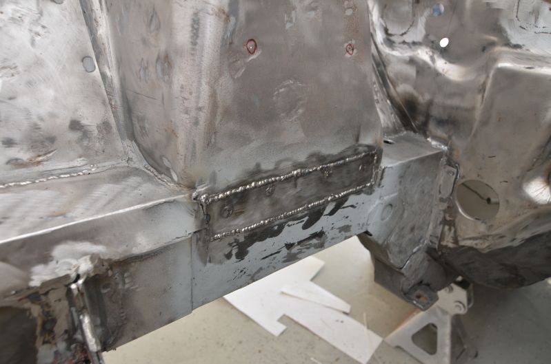
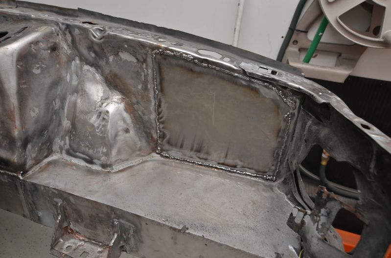
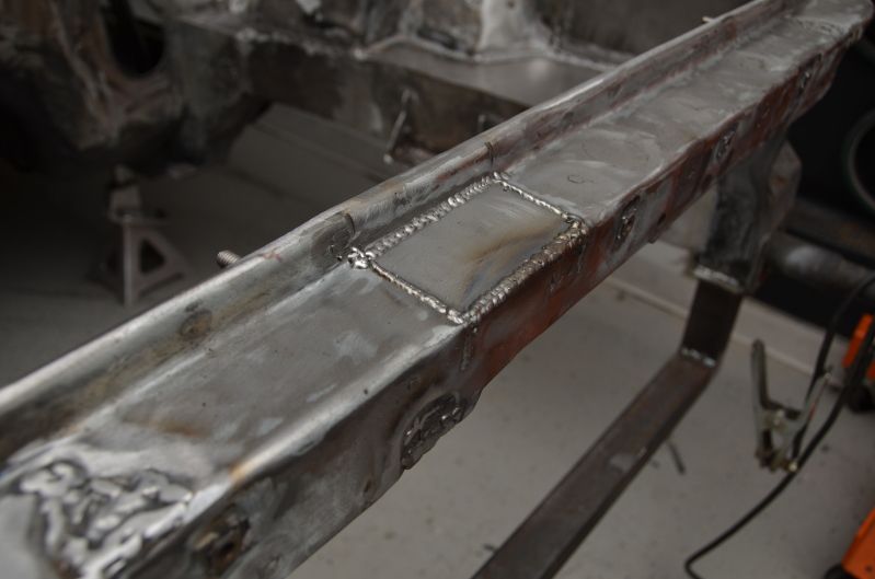
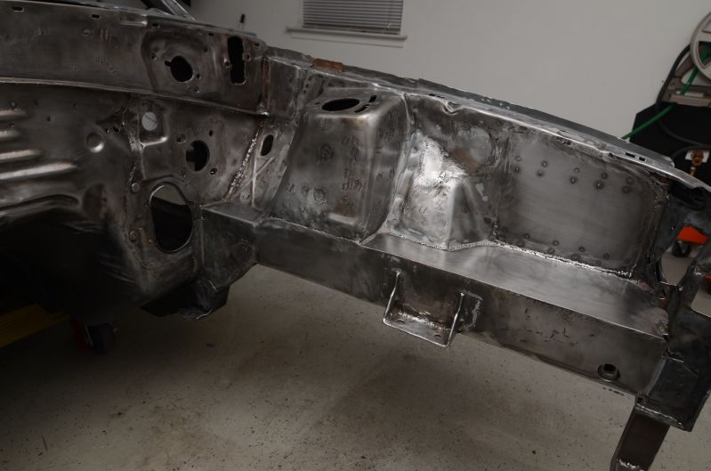
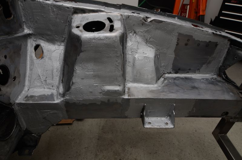
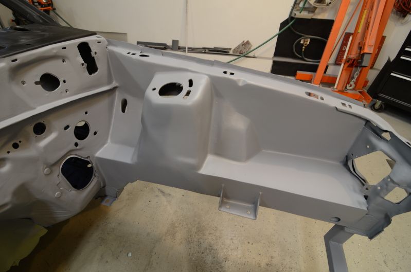
Got the framerail boxed in and welded up. I still need to cut out about 2" above it and replace that portion of the shock tower with new sheet metal. Once I do that, I can put one final piece of sheet metal over everything and smooth it all out.
Welded in the piece near the firewall.
Grinding down all those welds...
I also cut out the last bit of rusted strut tower metal. I'll make new pieces to replace the old and weld everything back up.
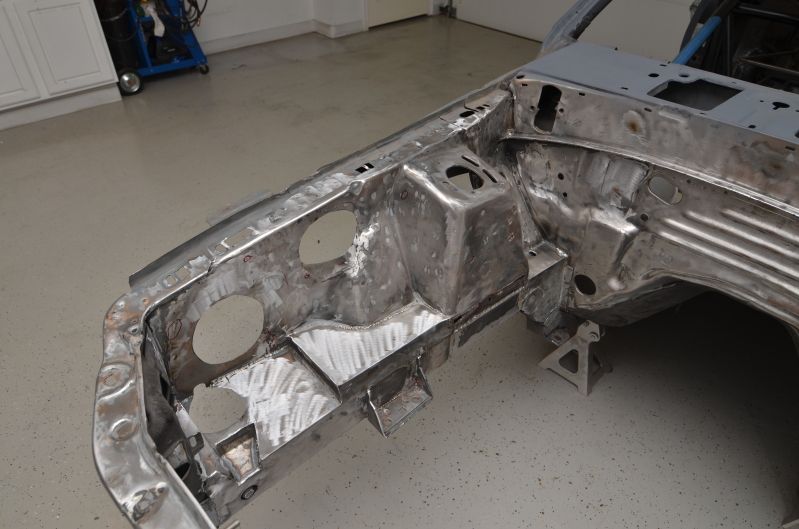
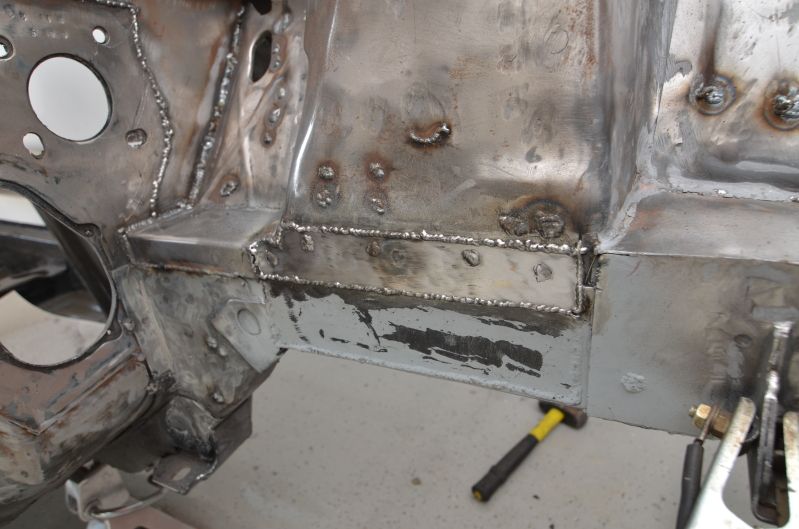
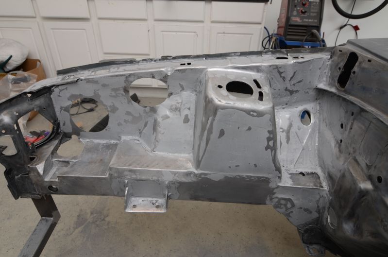
Finally finished the framerail repair. There was more involved to it than I thought, from making those tubular supports and welding everything up. But it's done, so I can move on to bigger and better things!
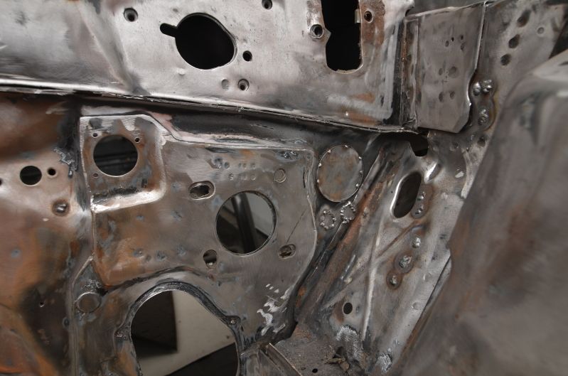
First I filled in the area I cut out and re-welded the spot welds where the sheet metal attaches to the strut tower.
Then I shot everything with paint and welded one more layer of sheet metal to complete everything.
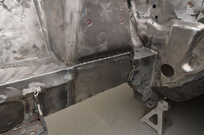
Just have to grind the welds down and then everything will be seamless. Luckily, I don't have much welding left to do in the engine bay.
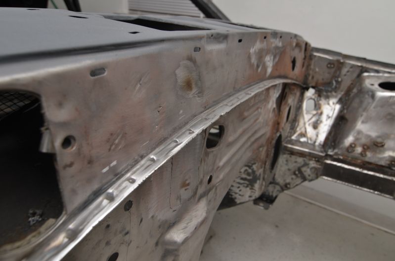
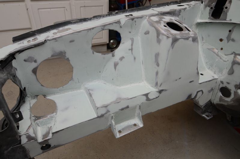
I decided to cut out the driver side apron and weld in a new, stronger piece. The original section had some rust issues and being that I plan to use that area to mount the ignition box and some other things, I wanted it to be in good shape.
Welded and grinded some of the front header support as well:
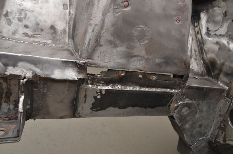
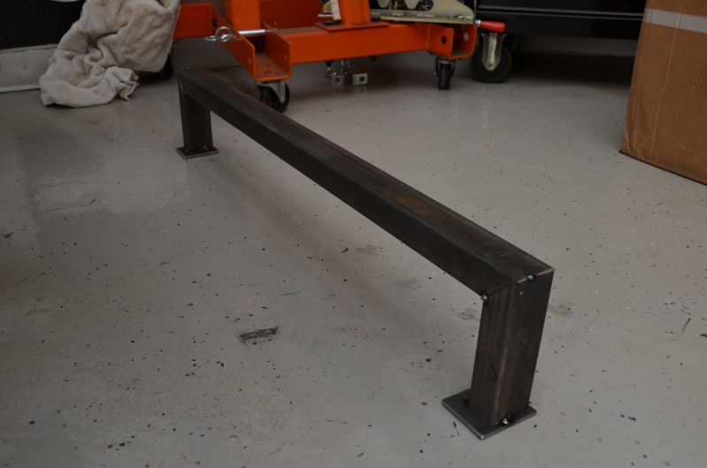
Welded in the new lower radiator support. For those that are wondering, I had to cut out the old one because I hacked it up so bad 7-8 years ago when I tried to stuff an oversized 3-row aluminum radiator in the bay. It was not in any kind of condition to bother repairing it. The boxed steel support I made is probably stronger anyway.
In addition to hacking the lower radiator support, I apparently gave the driver side core support some hell, so I had to cut and form a piece of steel to fix that area up. I sometimes wish I had the tools to stretch and form metal, but a mallet and a bunched up rag got the job done for me.
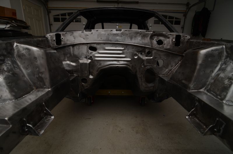
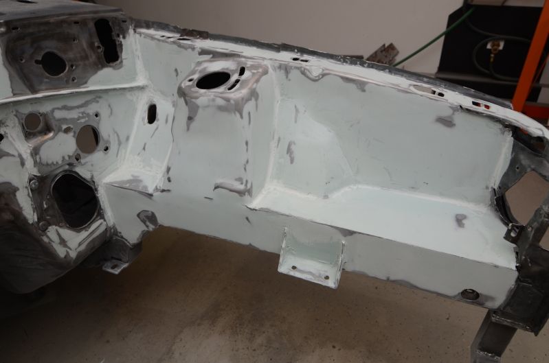
In the picture below, you can see the 'bump' on the passenger side of the core support.
That bump was bothering me, so I cut it out and welded in a new piece that will grind down flush with the rest of the support.
That is all pretty much the last of the welding in the engine bay area.
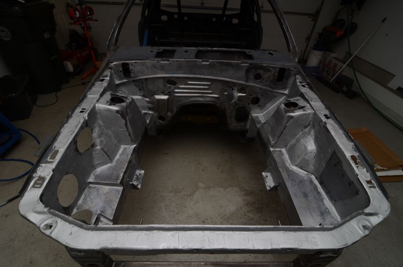
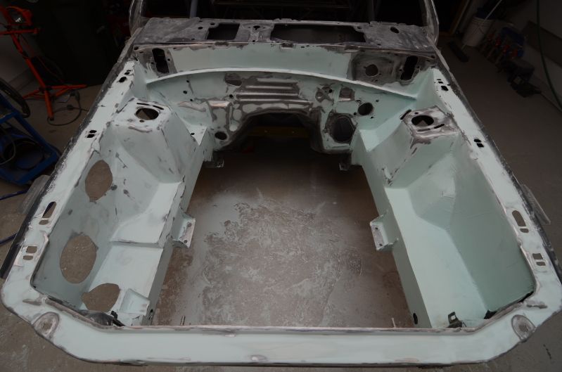
Filler time...
Put a layer of All Metal down in the major areas. This stuff seems to be love it or hate it in the autobody industry. I like the stuff. It's just very hard to sand down, but it's tough as nails and I don't have to worry about it cracking.
Sanded down the All Metal
Then I applied a light coat of Evercoat Z-Grip filler. I really liked the way it laid down, although I'm not very good at applying filler neatly. There were a lot of peaks and ridges that I needed to cut down with a chisel.
Next I started to block down the coat of filler. Got tired, so there is still more to do before I touch up areas with more filler.
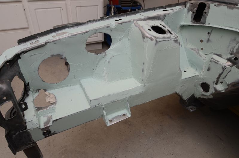
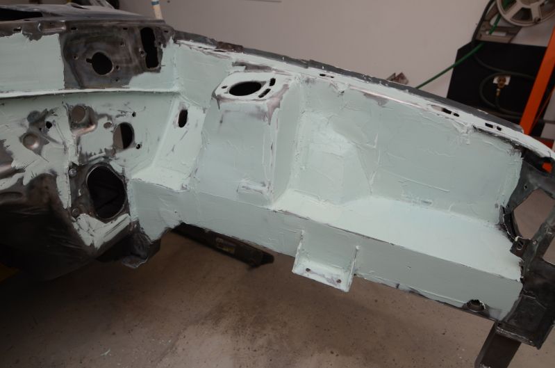
Put on a skim coat of putty. Passenger side sanded down.
Shot 4 coats of urethane. I have to sand it smooth and then assess how many imperfections are left. I can see a few right now, so I will probably a need to spot putty a couple trouble areas. Other than that, it looks real nice.
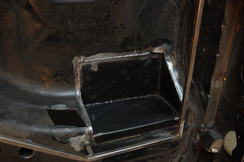
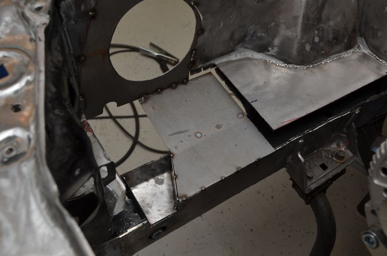
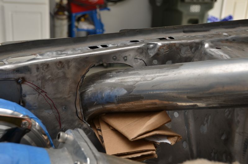
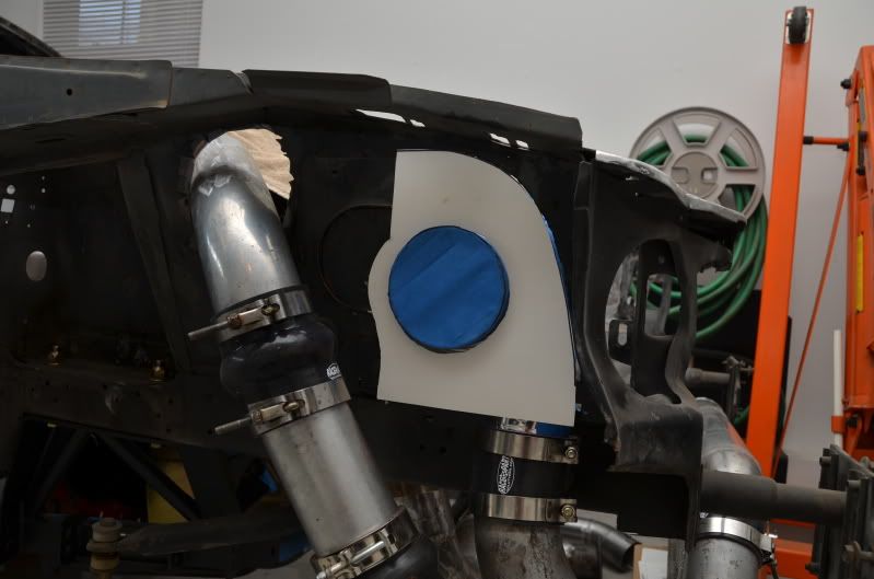
Just to recap, here's the mess I had to make of the inner fender apron to get the turbo to fit:
So, the solution was to box in as much as I possibly could to make everything look better and a little less butchered. Took a lot of paper templates and metal trimming to get it done.
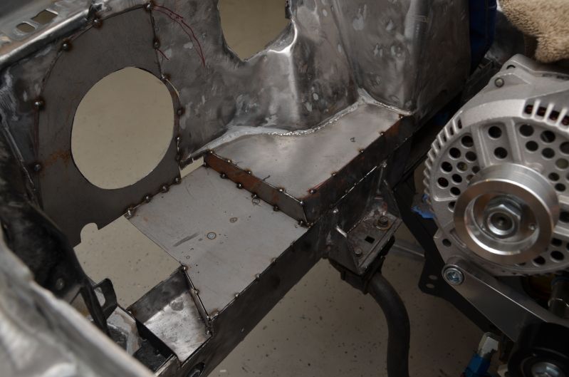
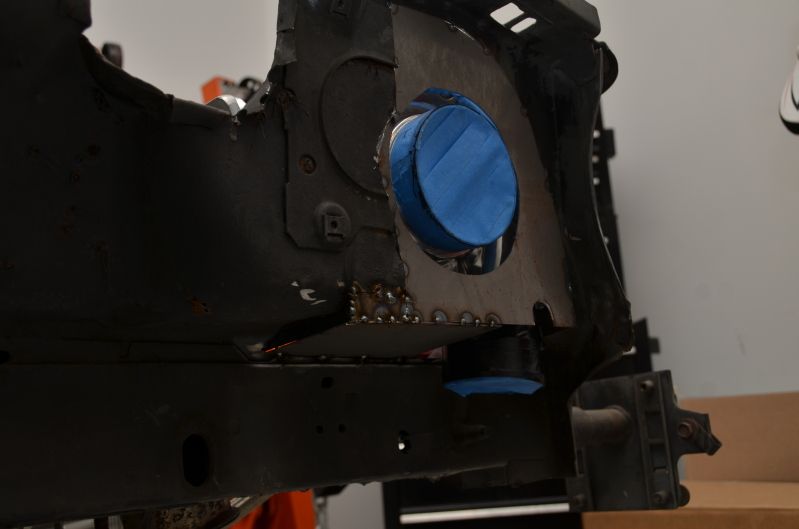
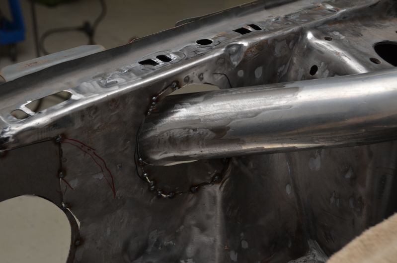
Used a cordless jig saw to cut a 5" hole for the compressor inlet
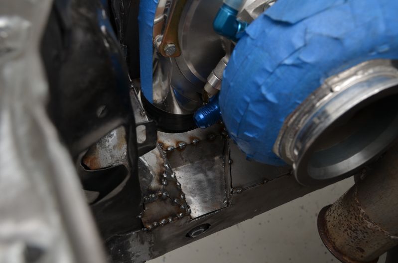
Cut pieces for the boxed out area around the drain fitting:
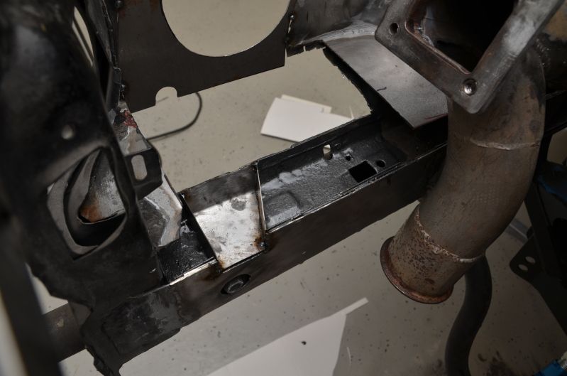
Cut more and more pieces to box the rest of the frame rail in:
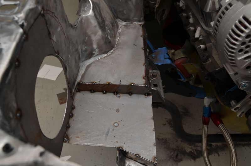
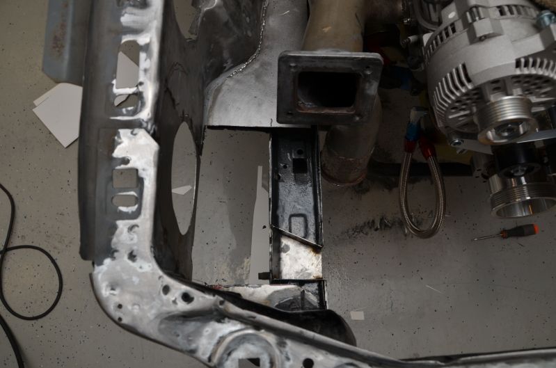
I still need to weld in that missing piece and I also want to weld in some radiused pieces around the outlet to eliminate the round peg in a square hold look. Everything fits pretty well though if you ask me!
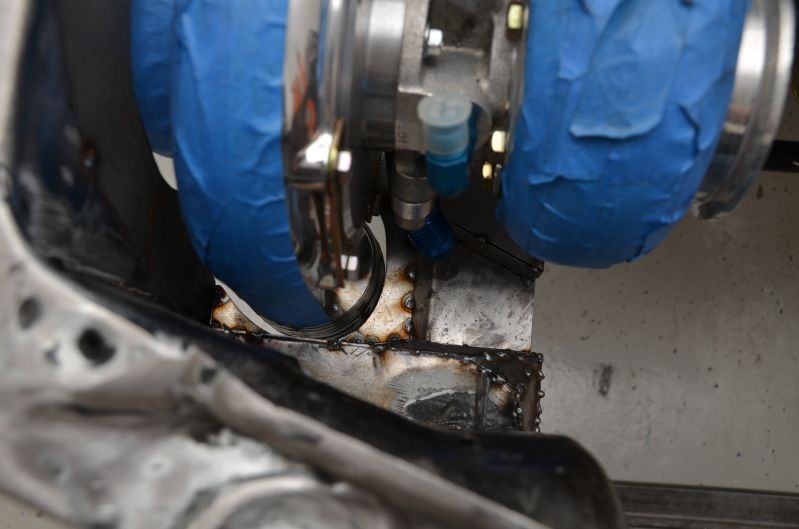
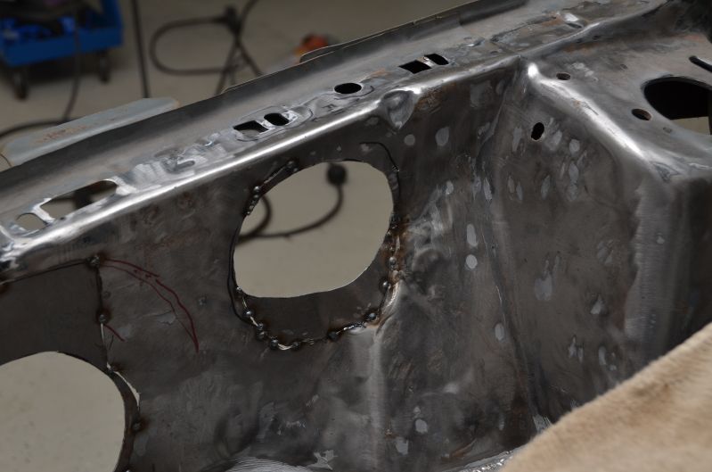
Welded a few more pieces in around the turbo discharge. Gives it more of a finished look as opposed to just a square hole.
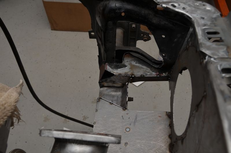
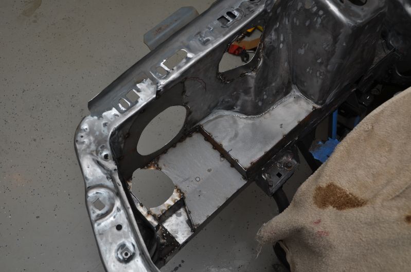
Also fabricated the lower radiator mount. This will get drilled and tapped for 2 mounting holes. I'll bolt the bottom radiator mounting flange to it. Rubber isolators will be used to dampen vibrations. I'll weld this to the frame once the engine is out.
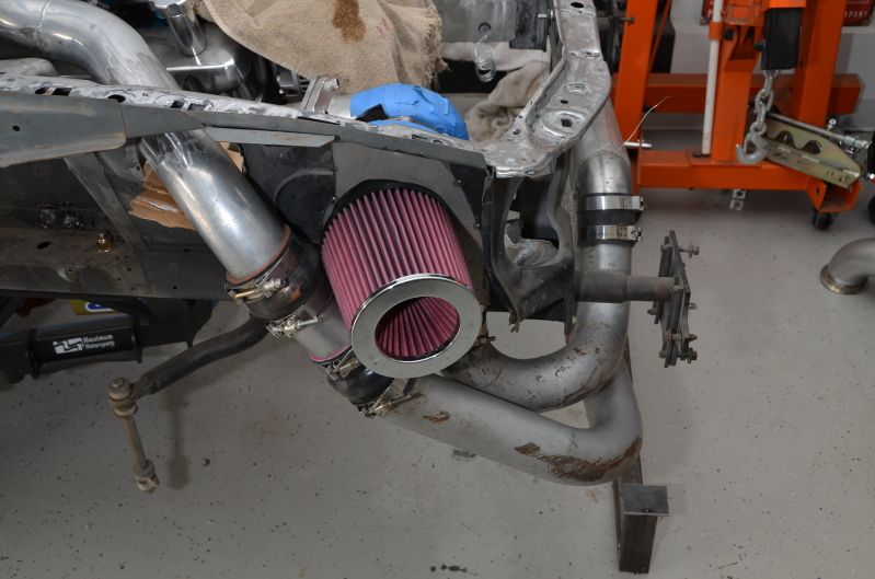
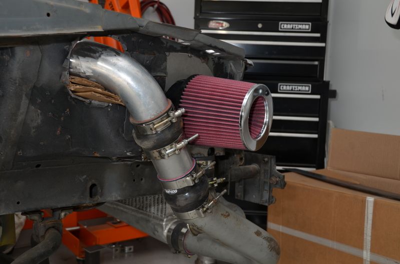
I checked clearances between the air filter, coldside piping and fender. All is well. It's tight, but it will fit.
Obviously, I can't have pieces of cardboard filling up the space in the hole for the discharge tube, so I cut some pieces and welded them in to tighten up the opening.
Finally, everything is all tacked together and ready to be fully welded:
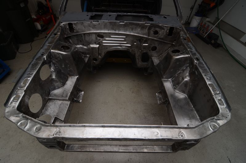
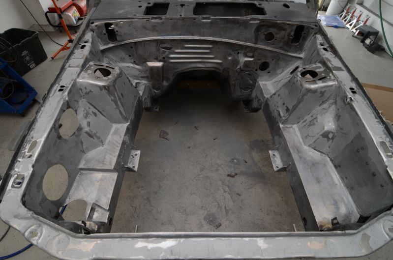
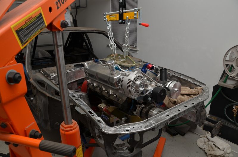
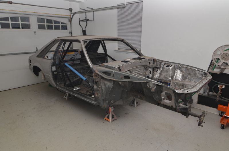
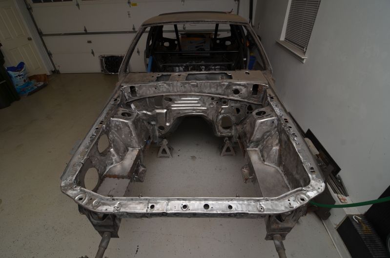
Engine is now out along with the trans, k-member, and IRS subframe. It's back to a shell...once again. I forgot that I had the cherry picker at the 1 ton mark instead of extended out to the 1/2 ton mark, so I was barely able to lift the engine high enough so the oil pan would clear the inner fender. I wouldn't have been pleased if I had to lower the engine back down again to adjust the hoist.
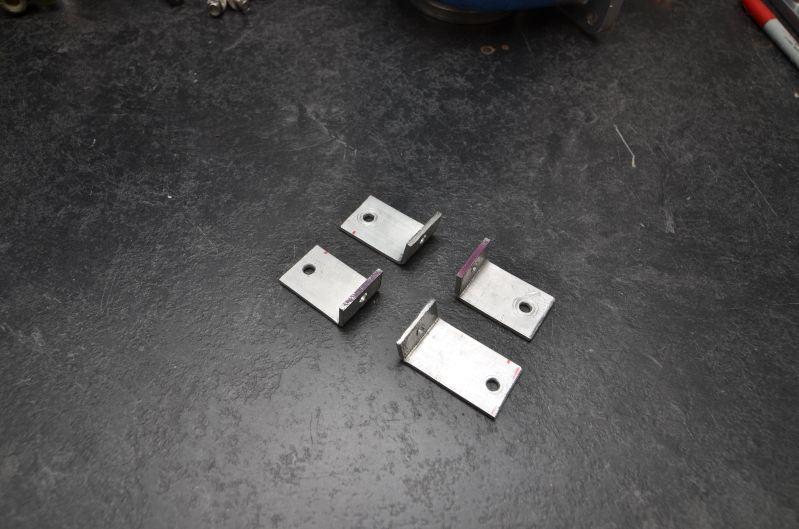
I did manage to fab up some brackets to mount my Taurus fan to my radiator. Took me longer than expected, but I move slow. I would be a terrible shop employee.
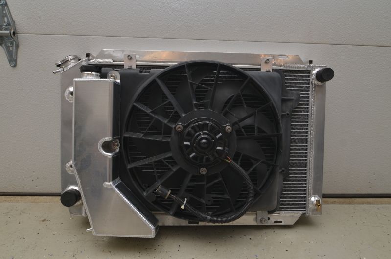
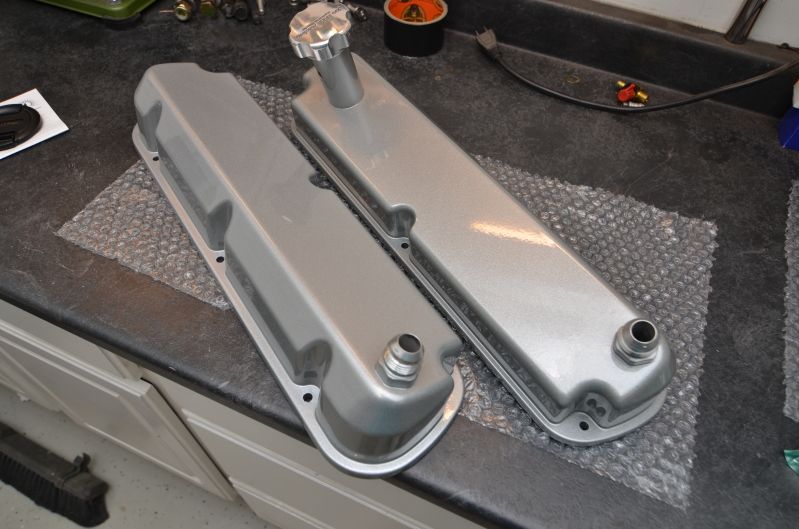
Here are the parts I got back from the powder coater. The harsh light does the coating no justice. This stuff sparkles and shines like crazy in the sun.
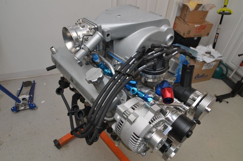
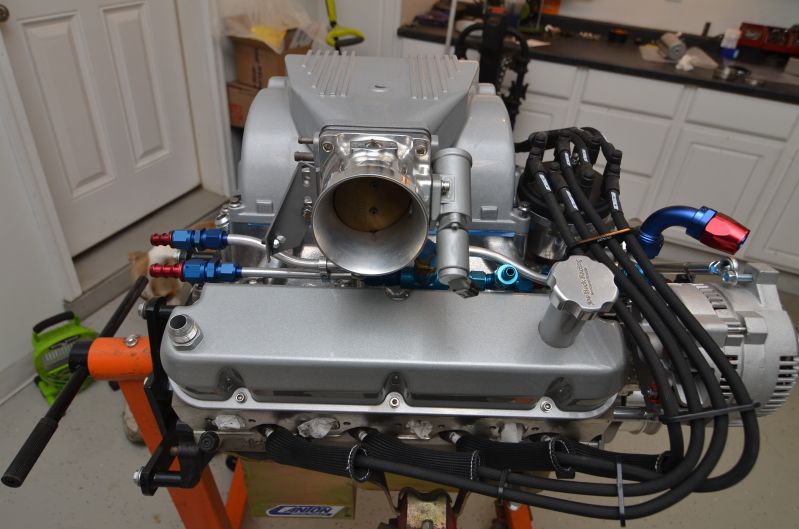
Also a picture of the DEI plug wire sleeves. Not only are they functional, but they look nice too. They were a pain to get over the 10mm Taylor wires though. They're each essentially one long Chinese finger trap. I even called DEI for some advice to speed the process, but they had nothing constructive to offer.
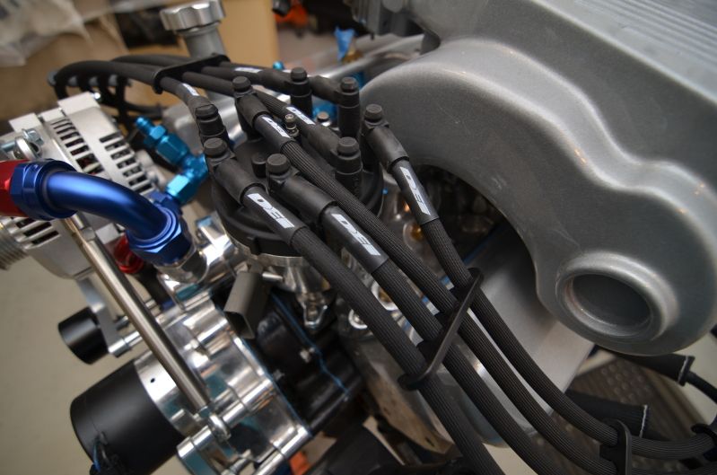
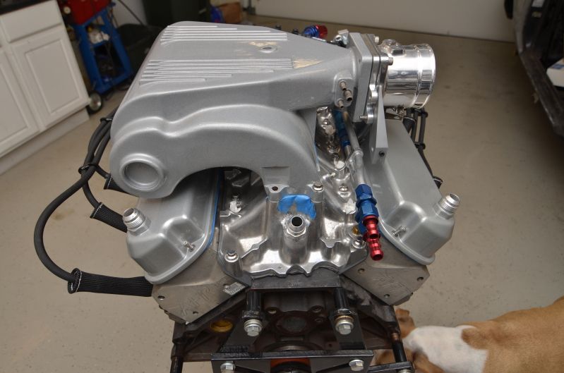
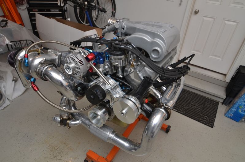
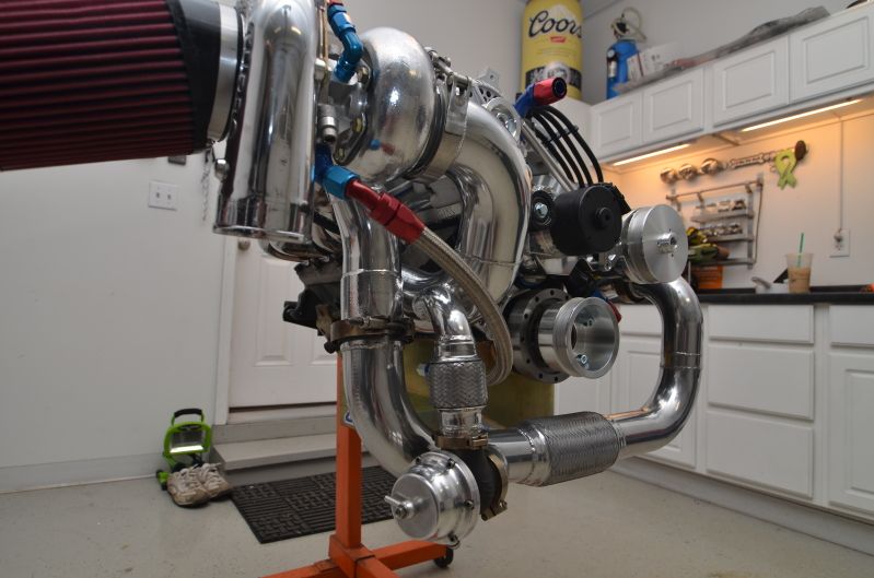
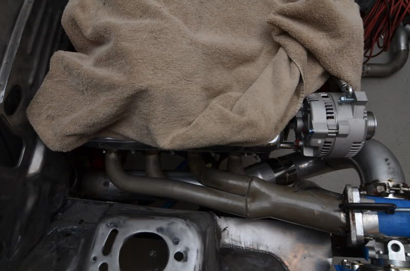
Here is the engine with a few more accessories added
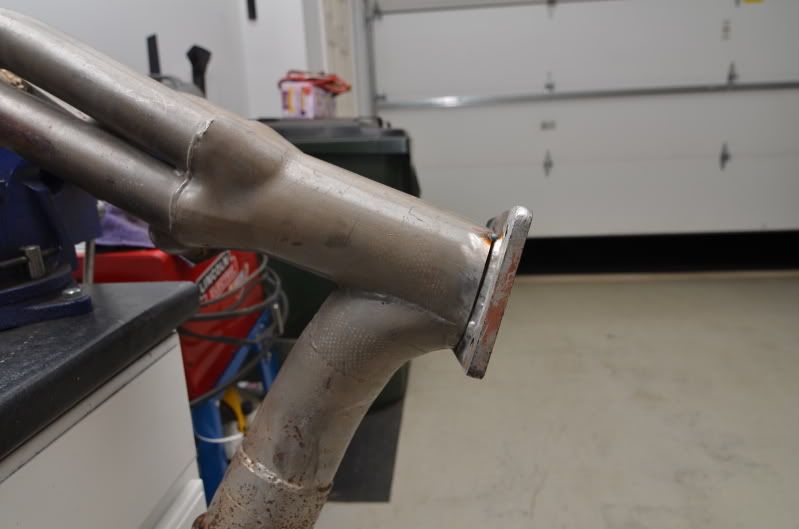
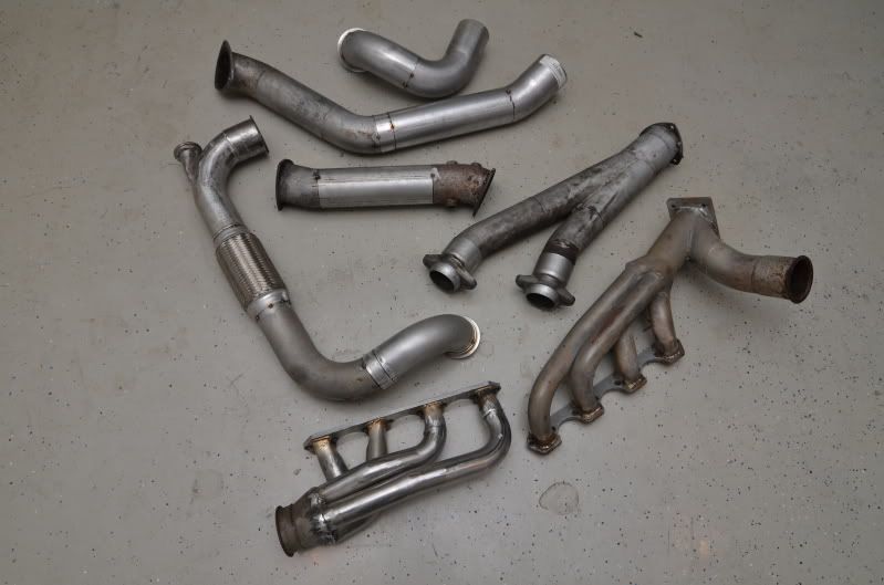
The only issue that I found with the pipes from Jet-Hot was a dent in the end of my downpipe. It's easy enough to bend it back into position though. You can see it in this picture
The rest of the pipes came out nice too
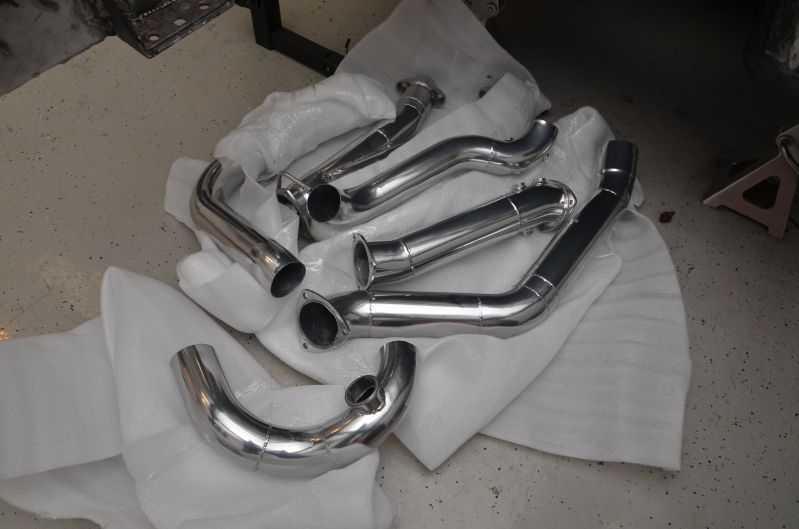
Call me ignorant, but I did not know Jet-Hot coated the inside of the pipes as part of their standard service. I though it was an "option" that you had to ask for. I didn't plan on coating the inside of mine, but every single pipe I got back was coated inside and out. I'm not complaining, I just didn't expect it. That definitely justifies the cost of getting the pipes coated. They really did do a nice job on them.
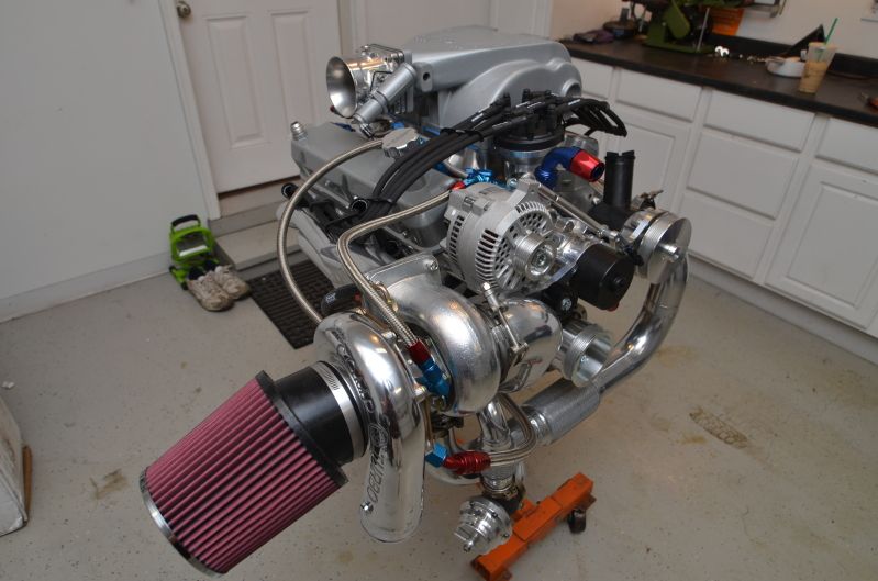
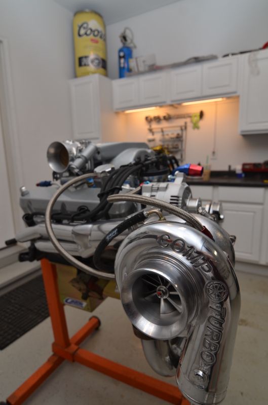
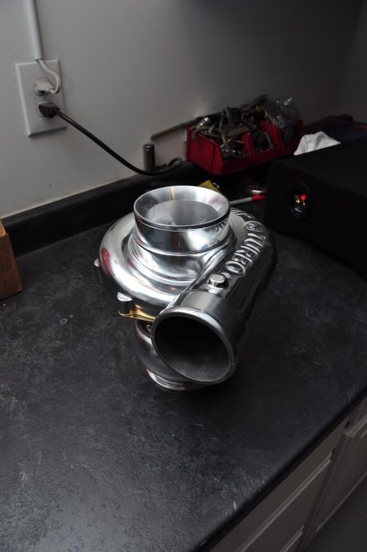
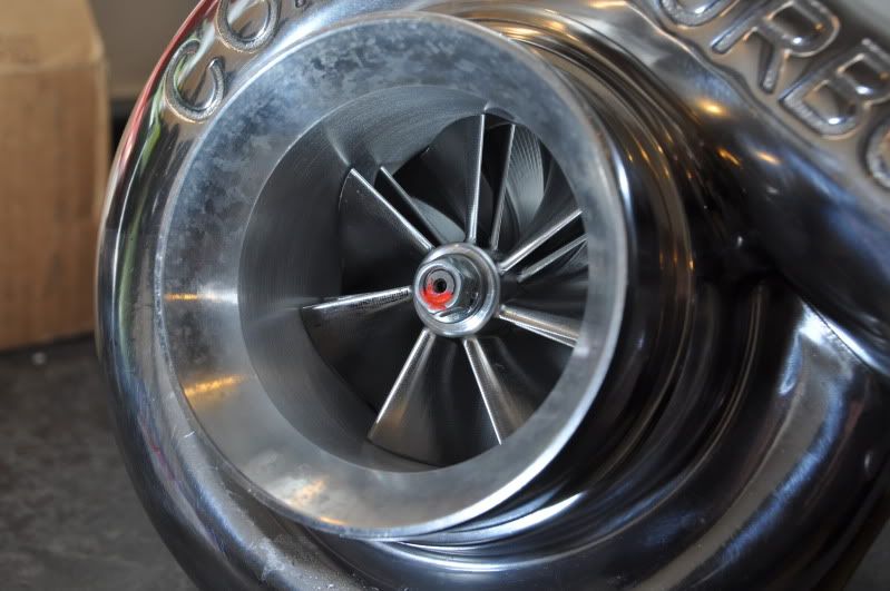
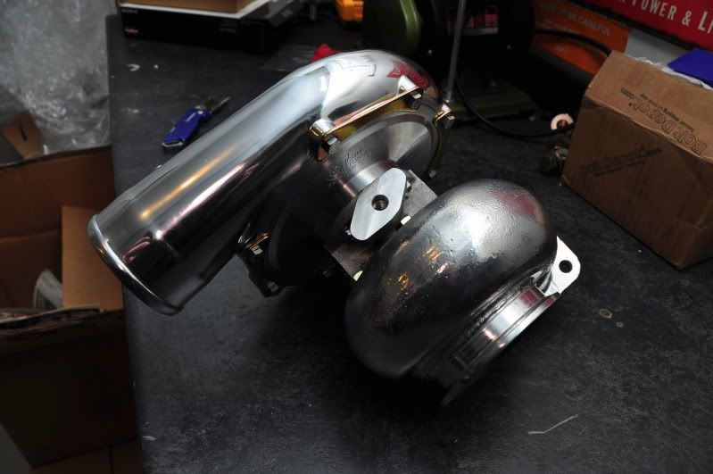
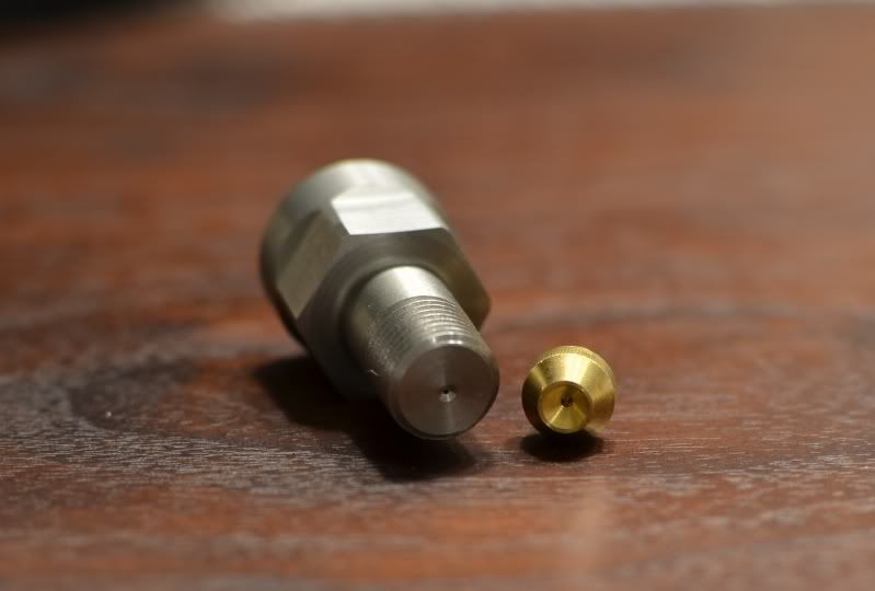
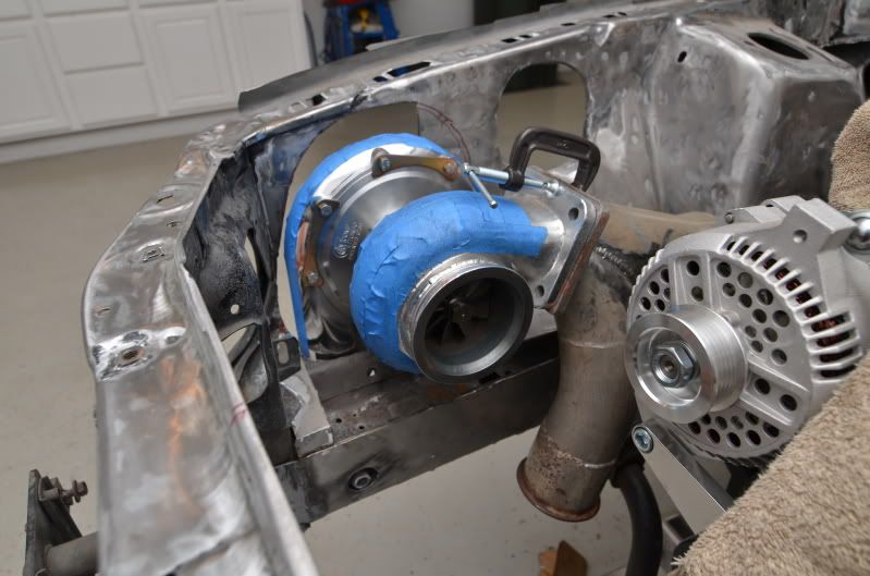
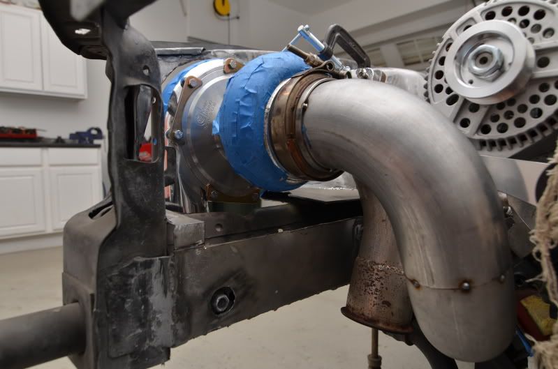
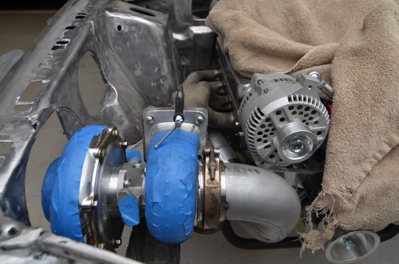
Here's the turbo. Comp 76mm triple ceramic ball bearing, water cooled, 0.96A/R
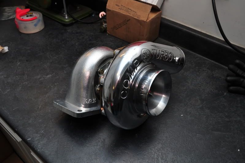
Here's a picture of the overpriced restrictor/adapter/filter I received from Comp. The orifice on this thing is SMALL. It's sitting next to a .041" restrictor. I can't believe how tiny that hole is. Comp was not kidding when they told me that these ball-bearing turbos hardly use any oil.
I had a bad feeling that the turbo was not going to sit the way I wanted it to being that the kit was originally configured for a 60mm turbo. I decided to cut away at the fender apron until I was able to get the turbo to fit. Unfortunately, this is how much I needed to cut out for it to work:
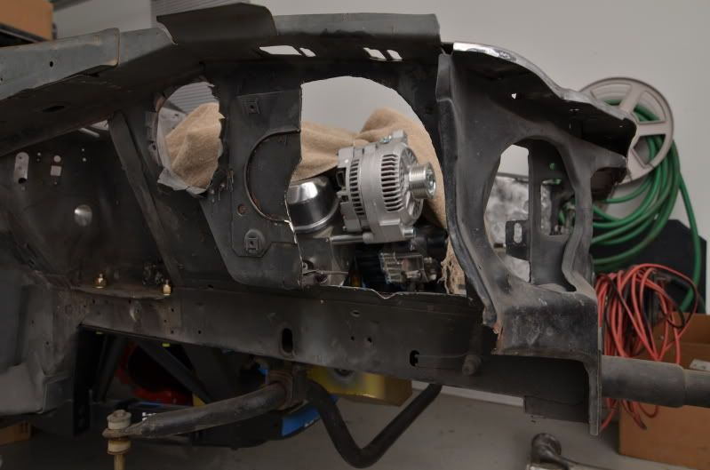
I didn't take any pictures of the turbo mounted, but the half the compressor housing was sticking into the fenderwell and the turbine housing was sitting inside the valley of the framerail. It was sitting WAY too low and too far outward. I needed to get it to sit higher and in towards the engine bay more. They only part I wanted sticking into the fenderwell is the inlet.
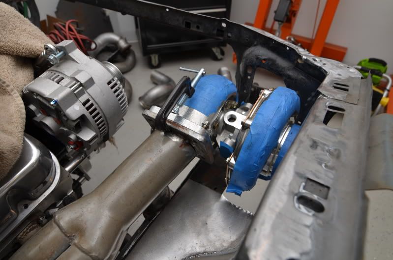
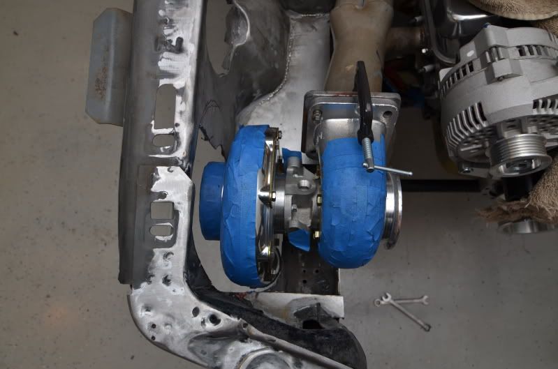
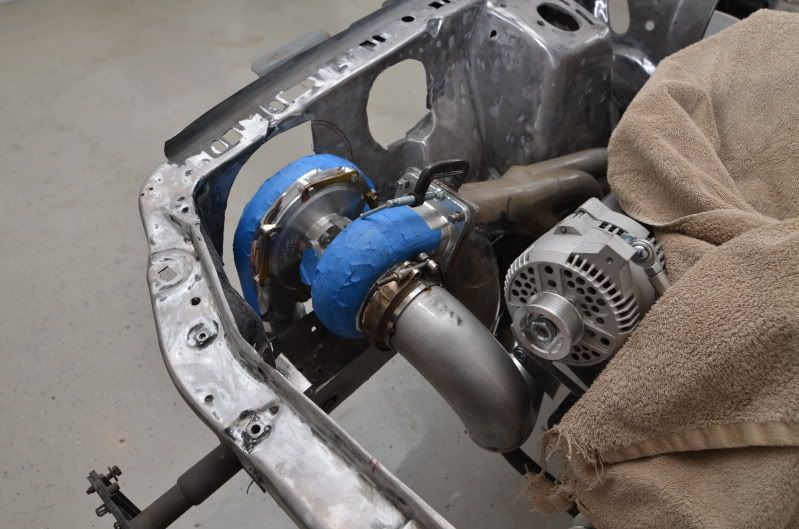
So, I need to chop away at the flange:
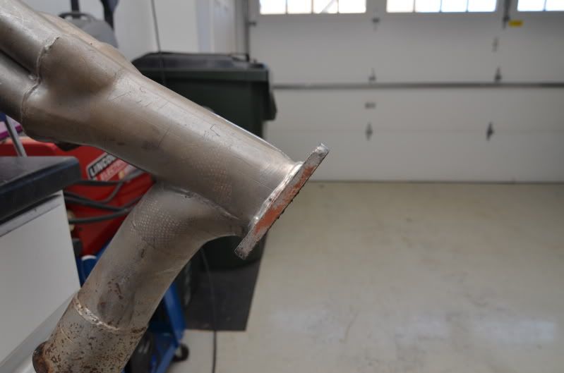
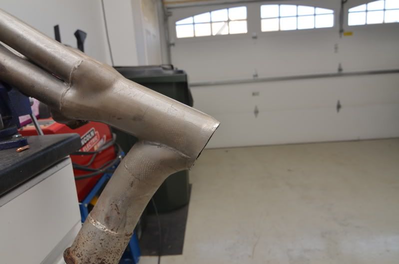
You can see the difference between the original flange mount and the "new and improved" mount.
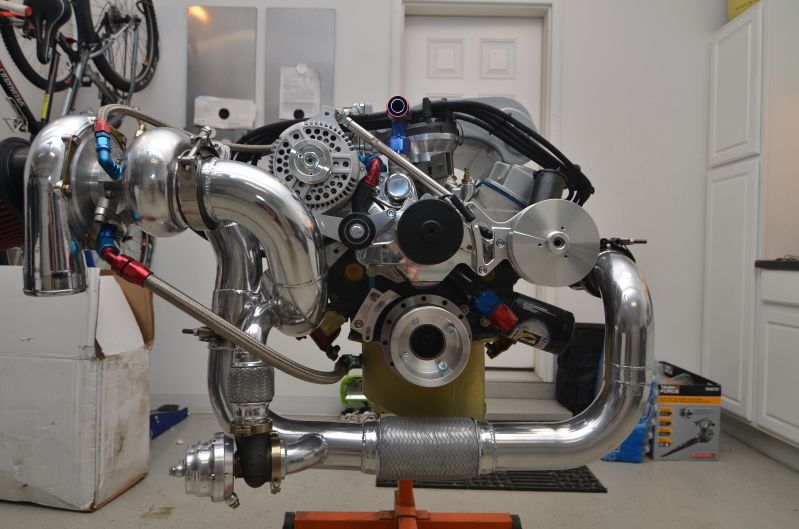
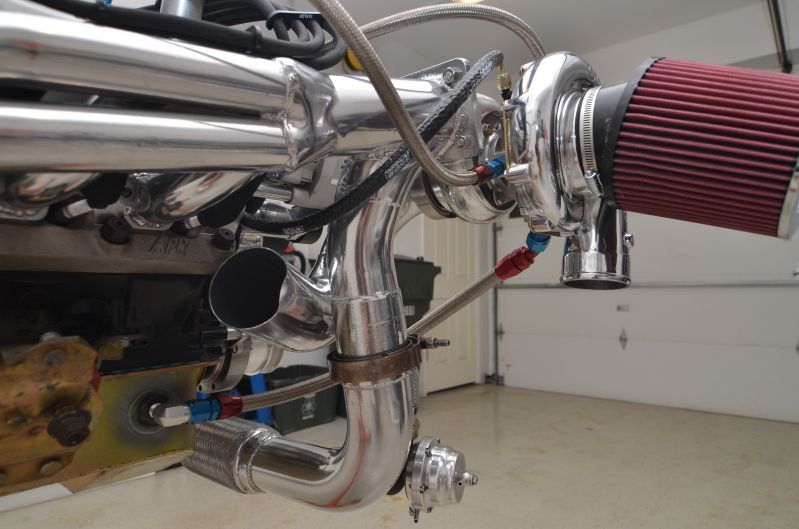
Doing this enabled my to get the turbo to sit in the engine bay the way I intended:
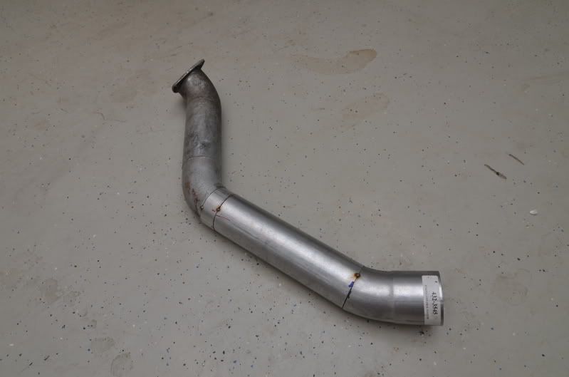
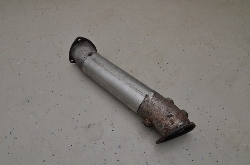
I then needed to build a new downpipe, because the original one was beat to hell. Here is a comparison between the two:
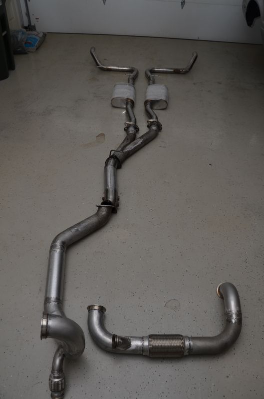
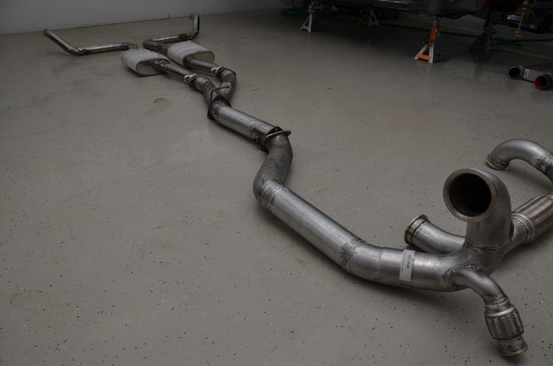
I then used a combination of new pipe and old stuff to finish the rest of the exhaust:
It took FOREVER, but I was actually able to make everything fit without hitting anything.

I'm pretty happy with the way everything came together. I'm glad I got the kit for cheap, because I needed to put a serious amount of time into it to get everything to fit and look the way I wanted. I bought a "rough" kit for that reason, because I knew I would want to make tweaks to it.
Once I weld everything up, it will all get shipped off to Jet-Hot so those pipes can look as pretty as they deserve to be.
Oh, and I will be repairing that fender apron as well as re-boxing the frame rail. There will just be a 5" diameter hole in the apron so the inlet can stick through.
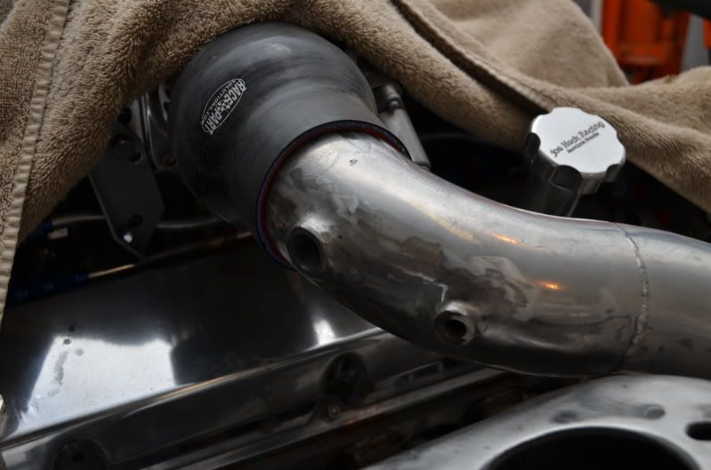
I fully welded up all the downpipe sections. I also welded a 3/8" bung for the ACT sensor and two 1/8" bungs for the methanol nozzles. You can't see the one nozzle bung in the picture.
I also made the template to repair the gaping hole in the inner fender.
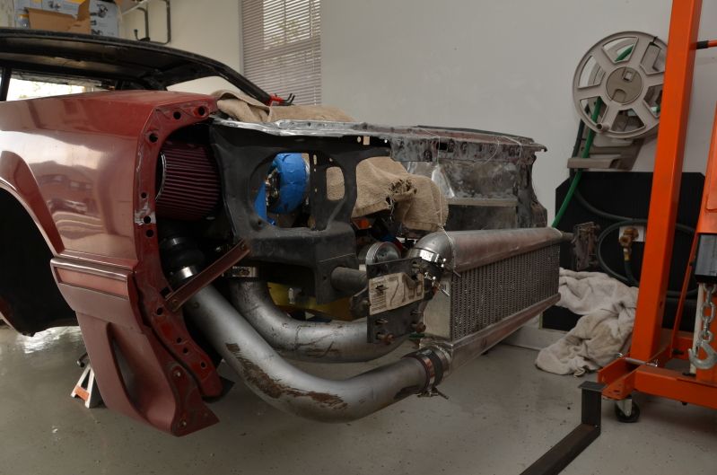
Mocked up the coldside. Everything fit together great. I'm going to have to get some tabs welded to the intercooler to have it supported from above.
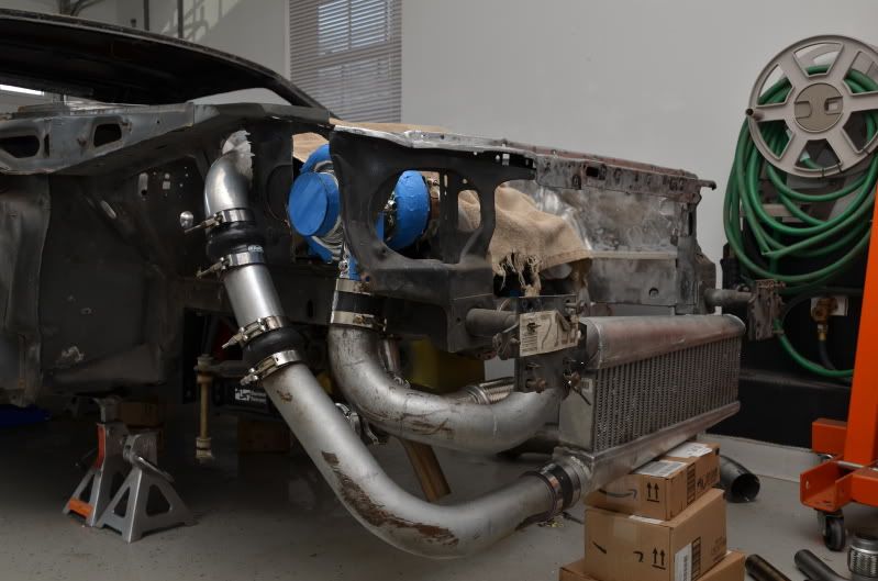
The only conflict that I ran into was between the blow off valve and the wastegate. Because I am recirculating the wastegate back into the downpipe, I need to install a 1-3/4" pipe from the discharge side of the gate to the downpipe. The HP kit was not designed to recirculate the gate, so my discharge pipe sits too close to the blow off valve for my liking.
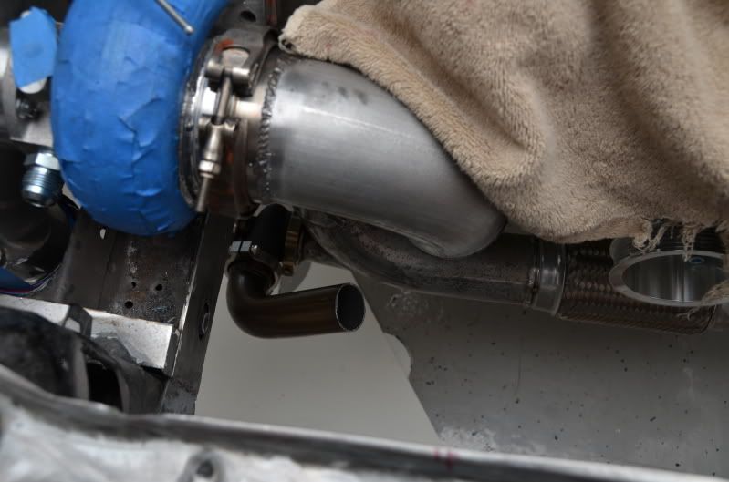

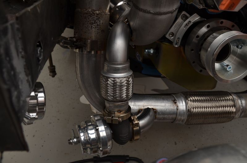
I do not really have any other good location for the BOV, and I really don't feel like cutting off the flange, moving it, and repairing the pipe. Soooo, being that I'm not even really happy with the condition of the passenger side of the crossover pipe and I plan to replace it anyway, I'm going to relocate the wastegate closer towards the flex bellow.
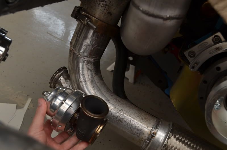
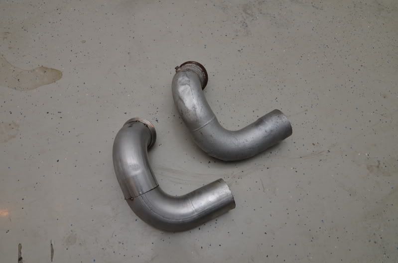
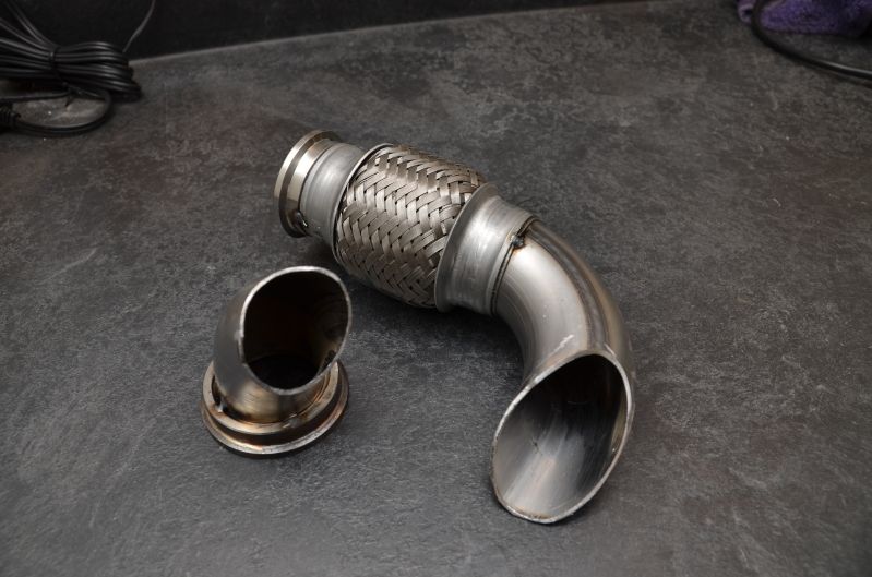
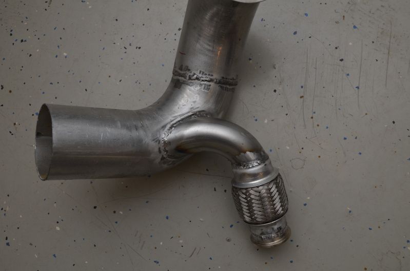
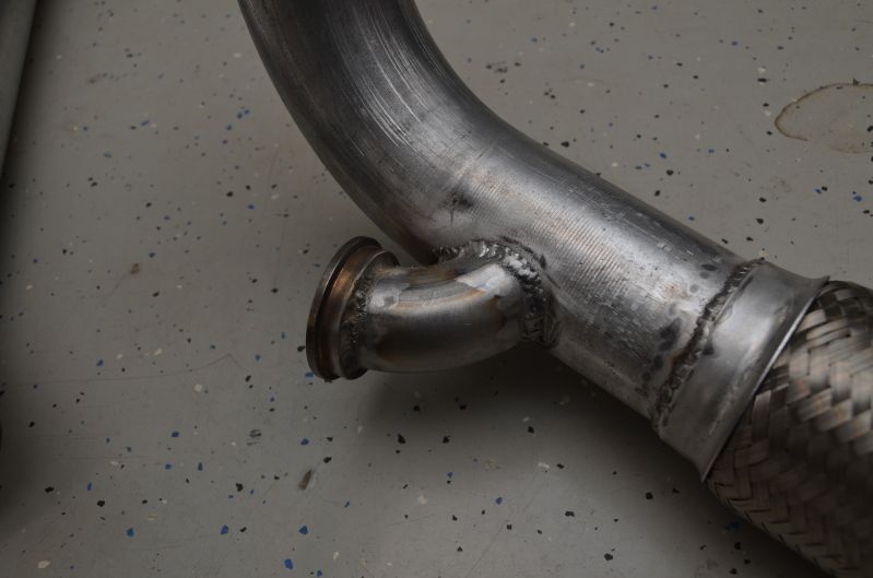
I'll install a 90 degree bend right off the crossover into the wastegate inlet. This will allow me to run a straight pipe (and flex bellow) directly up into the downpipe. I'm going to install a 90 degree bend off the downpipe facing down. This will ensure that the exhaust gas getting dumped into the downpipe is going the same direction as the exhaust gas coming out of the turbo.
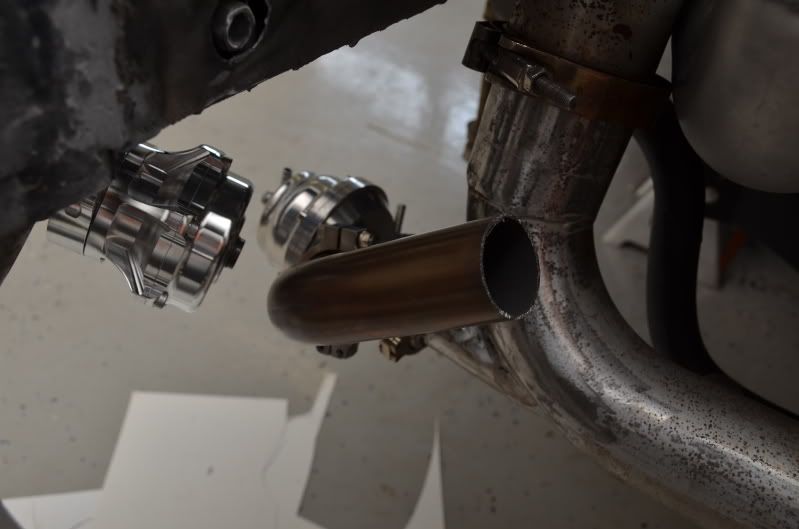
The other option is to keep the wastegate inlet in the same place on the crossover, but instead of it coming straight out, I'll install a 90 degree elbow, which will provide enough clearance to the BOV. I'm just going to have to re-check the clearance to the radiator/fan shroud for that option. It may be close.
Part of the challenge for the wastegate placement was that I needed to position it so that I could fit a flex bellow between the discharge and the downpipe. I also wanted the discharge to connect to the downpipe in a configuration that would enable the exhaust from the wastegate to flow in the same direction as the exhaust from the turbine housing. I didn't want the wastegate discharge to have to "fight" the exhaust from the turbine in fear that it would affect its ability to control boost.
Here are the pipes that I labored over for hours (literally) to get them just the way I needed them to be:
Attached to the wastegate:
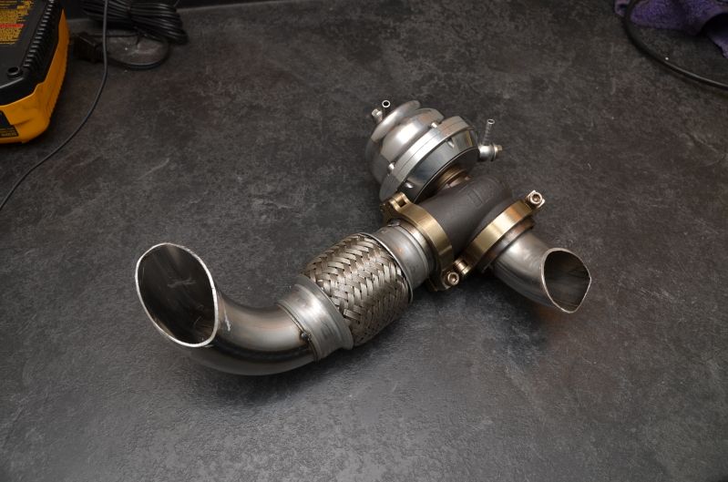
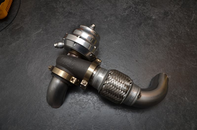
And tack welded in place:
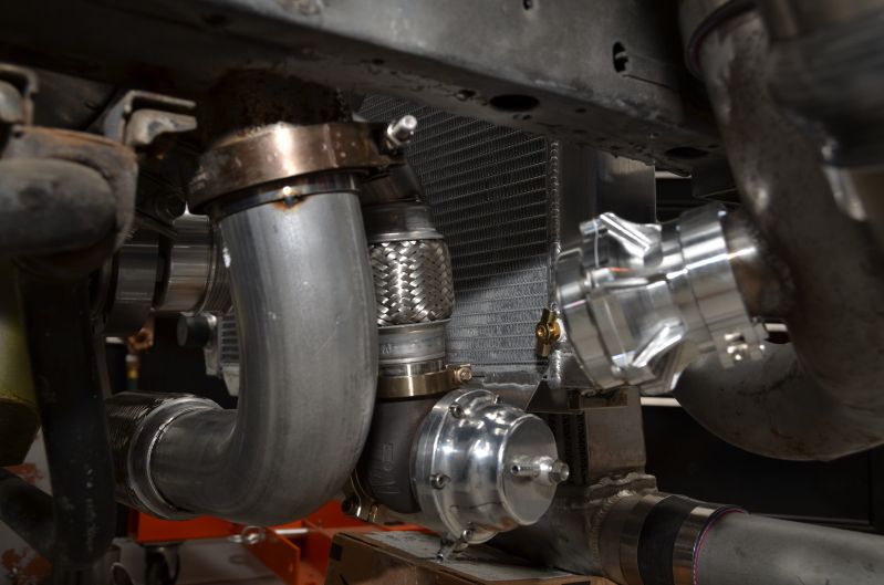
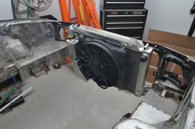
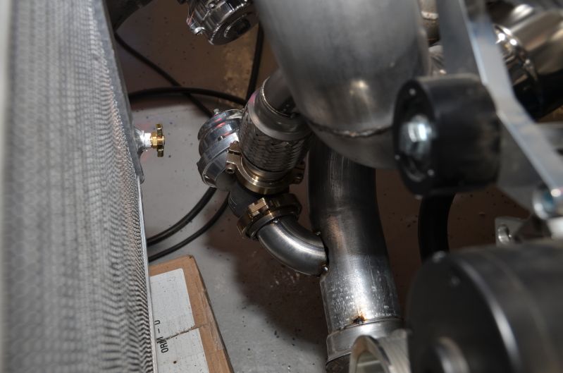
Good radiator clearance:
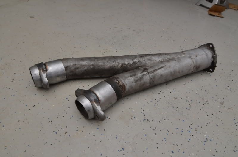
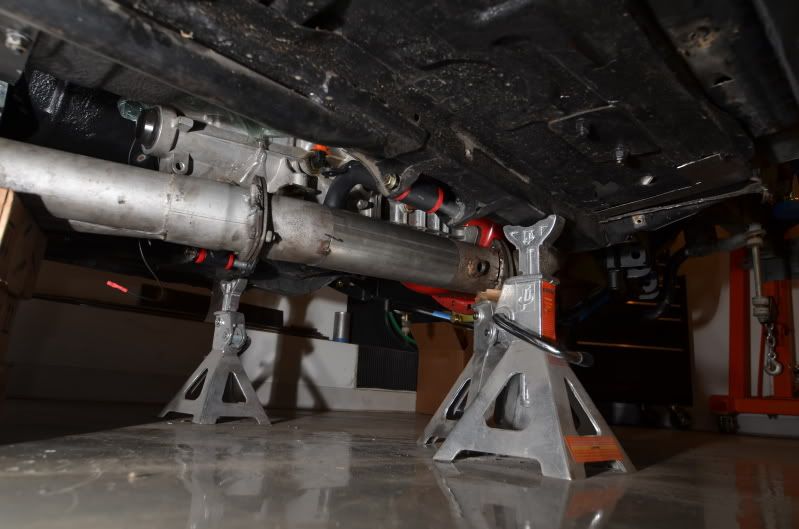
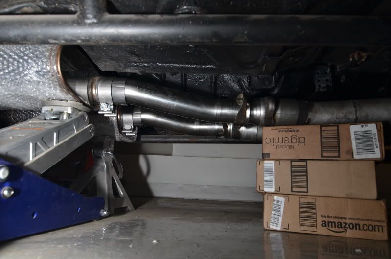
Finished up the welds on the rest of the exhaust piping:
Bent an exhaust hanger and welded it to the y-pipe:
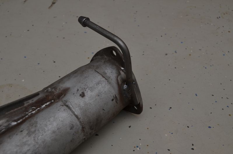
This is the only hanger between where the downpipe mounts to the turbo and the tailpipes right behind the mufflers. I had everything tightened down and it seemed solid, but if I need another hanger down the road, I can just get one of those deals that strap around the exhaust pipe.
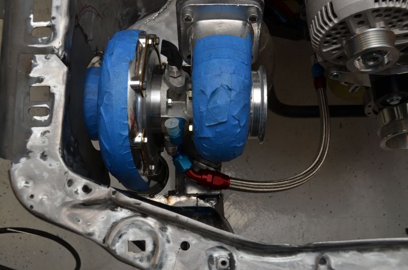
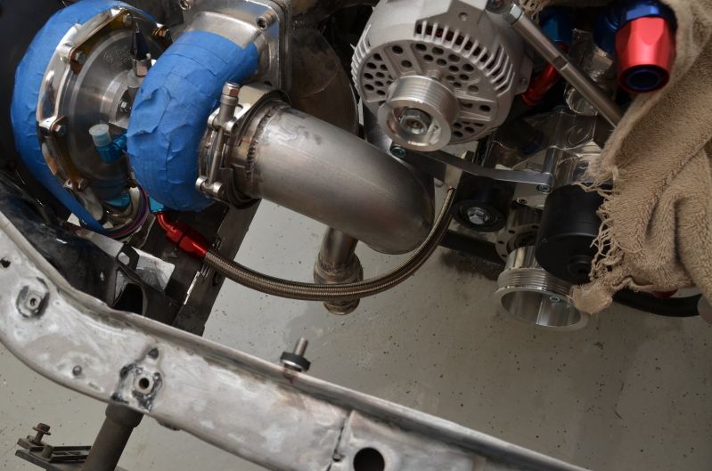
I also bought some AN adapters so I could tap my heater lines for the water feed to the turbo:
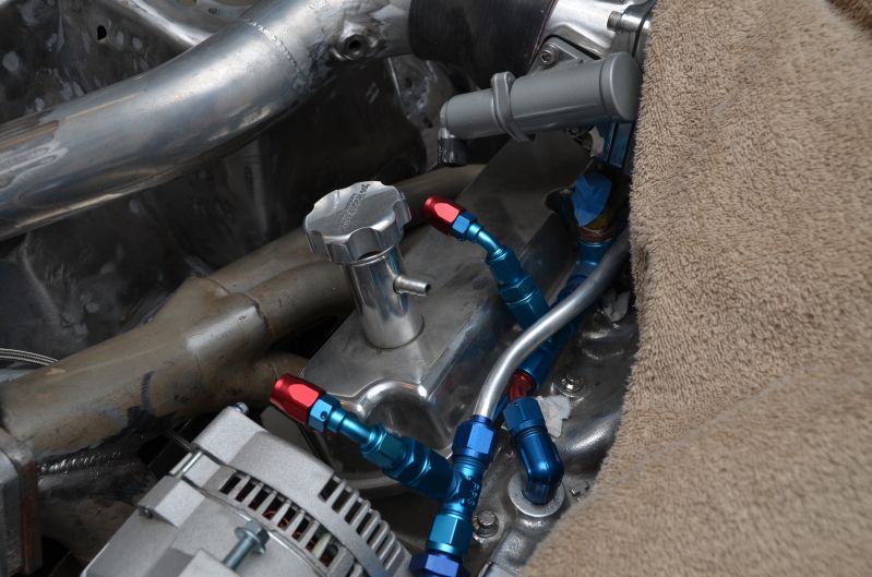
Because of the location of the flange and the way the turbo sits, I had to clock it slightly so one water line would clear the flange. It's only clocked about 10 degrees. The general rule of thumb seems to be not to clock it any more than 20 degrees, so I should still have adquate oil drainage.
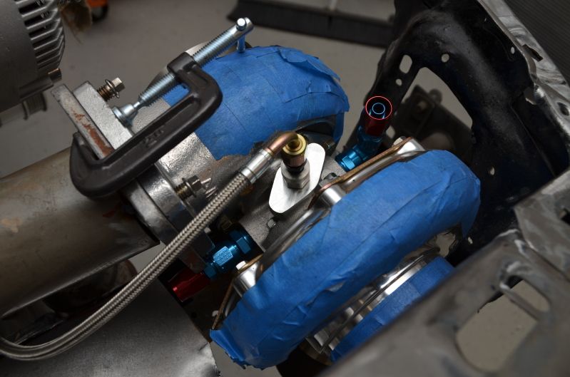
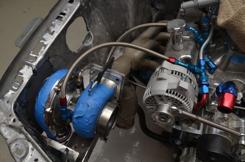
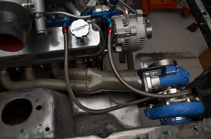
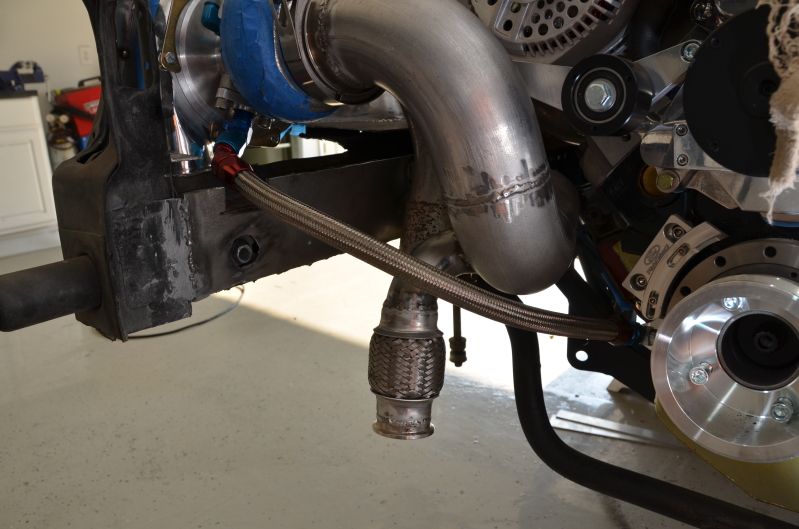
Here are the water lines all done:
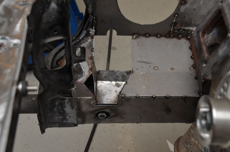
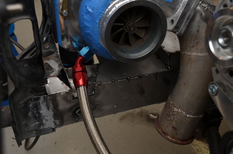
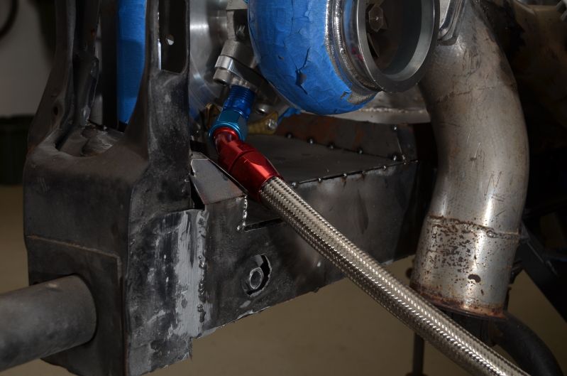
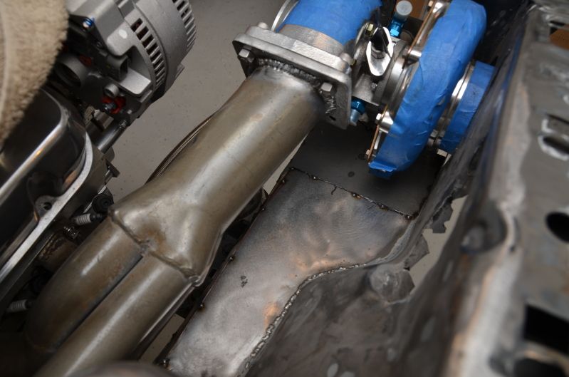
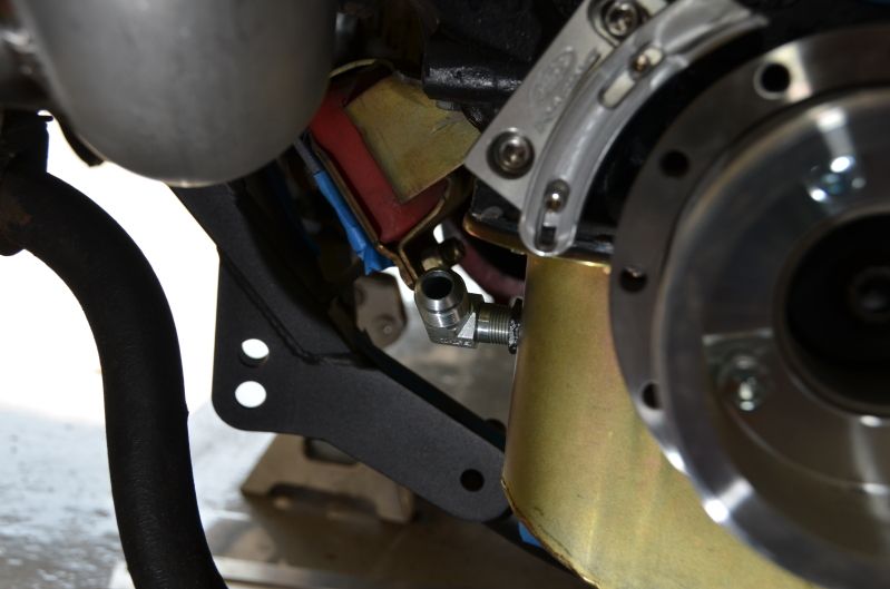
I figured out a combination of AN fittings that would allow me to more easily install the oil drain. I had to notch the frame rail for the fitting to have the right pitch.
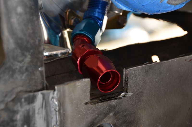
90 degree fitting out of the pan:
Line installed:
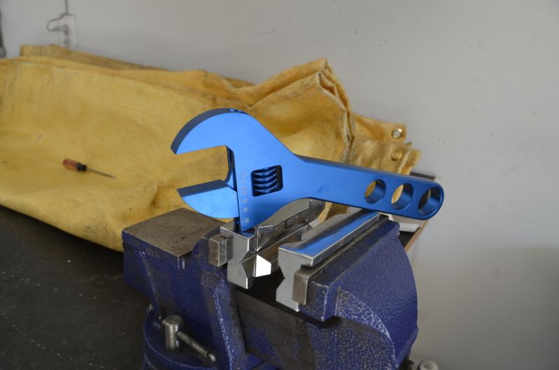
For those that are curious, here are the tools I use to assemble the AN fittings. Adjustable aluminum wrench and aluminum vice inserts. Works really well.
I just need to weld up the turbo mounting flange on the passenger header and then I'm going to drop off all the piping at the local powder coating shop so they can sandblast everything. I want to make sure the imperfections in the pipes are all gone (or at least visible so I can fix them) before I send it away for ceramic coating.