
You are using an out of date browser. It may not display this or other websites correctly.
You should upgrade or use an alternative browser.
You should upgrade or use an alternative browser.
Efi To Carb
- Thread starter tmartintk
- Start date
-
Sponsors (?)
That wasn't the best choice, I hope that you got the car dirt cheap - less that $1000. If not, then you got robbed.
A word of warning on EFI to carb swaps: don’t expect to pass emissions in any state that does comprehensive smog inspections, because it won’t happen. Some states will not title or issue license plates to cars that have been converted from EFI to carb. Be aware that you are violating several Federal laws concerning the removal of pollution control equipment. If you operate the vehicle on public highways and get caught by state or federal law enforcement (doubtful, but possible) you could be subject to fines and imprisonment. You won't get any more power from a carb than you will from EFI.
The following information is intended for informational purposes only. Operation of a motor vehicle modified in such as manner as described below should be limited to off road use only.
Doing the swap: You must know how to read electrical diagrams and wire circuits properly to do the swap. Don’t take shortcuts or cut corners in the fabrication of the electrical or mechanical assemblies. If you do NASCAR quality work, the car will look good, run good and be as reliable as a carb’d car can be. Take pride in a job done with excellence.
If you are one of those few people who do excellent work, please disregard my negative comments. They are not intended for you.
Quality, quality, quality…
Some of the motivation of my negative comments about EFI to carb has to do with the quality of electrical workmanship. A lot of the wiring “repairs” that I have seen on the road and in the junkyard looks like road kill. The other part of my negative view stems from people who can’t grasp the operation and tuning of EFI. Carbs have their own set of requirements and some learning is required to get the best performance. Every car is different and each installation needs to be tuned to get the best performance. Putting an “out of the box carb” or one from someone else’s car isn’t the way to success. There is no auto compensation for small variations in carbs like there is for EFI. Just throwing a carb on a car because you won’t bother to learn how EFI works is a poor excuse.
Now that the rant is over, here’s some practical advice…
1. Do not use an EFI in tank fuel pump with a carb. You will never get the pressure/flow regulated properly. If the add on pressure regulator fails, you will flood the engine with gas and wash all the oil off the cylinder walls. That will cost you big time $$$. Either go full EFI or use a tank/fuel pump/fuel lines out of an 84 or earlier Stang. Fabricating your own setup is possible but there are some snags to overcome.
2. Do not attempt to leave the EFI computer in place in an attempt to control either the electric fuel pump or ignition. Doing so qualifies you for the “Road Kill Mechanics Award”.
3. If you try to use your current tank, you will need to pull the fuel pump out and fabricate a pickup tube & strainer sock to replace the fuel pump. Or you can have a sump fabricated and welded onto you existing tank. Many welding shops will not weld fuel tanks because of the dangers involved if the tank isn't purged properly.
4. You will need an external electric fuel pump unless you change the timing cover for one with the mechanical fuel pump mount on it. Rip all the EFI wiring out, and the computer controlled fuel pump won't work. You will need to add a relay & switch and wire in the existing inertia switch for an external low pressure electric fuel pump. Do not try to wire the fuel pump without the relay. The 15-20 amps the pump pulls will overload the circuit. This will take power away from other items on the same circuit or cause the fuse or fuse link to blow.
5.
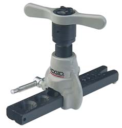
6. You will need to run some new fuel feed lines or braided hose. The 3/8" aluminum tubing works well, but you will need a flaring tool and bending springs to fabricate the lines. Braided hose is easy to run and route, but is much more expensive. It is about $3.50-$4.00 a foot plus the end fittings, which are $3-$4 each. Fabricating hose assembles can be difficult, but anyplace that makes hydraulic hoses can do it for you for an extra charge. See http://www.amazonhose.com for more information.
7. For some help fabricating your own stainless steel hose assemblies, see
8. http://www.turbinefun.com/Stainless_Braided_Hose_Assembly.asp
9. For stainless steel braided hose and fittings for automotive use:
10. See http://www.summitracing.com/search/?keyword=stainless steel hose&dds=1
11. http://www.summitracing.com/search/?keyword=stainless steel hose&dds=1
12. http://www.jegs.com/webapp/wcs/stor...hall&searchTerm=stainless+steel+hose&x=18&y=4
13. See http://www.eaton.com/Eaton/Product...rformanceProducts/FittingsProducts/index.htm for more information on High performance automotive hose products
14. AN fittings require a 37 degree flaring tool. A standard automotive or household plumbing tool is 45 degrees and cannot be used with AN flare fittings. If you do, the flare is subjected to too much stress when the fitting is tightened, and is likely to fail or leak.
15. See http://www.mscdirect.com/ , http://www.mcmaster.com/ or for the flaring tool you will need . Prices start at $85 and go up
16. http://www1.mscdirect.com/CGI/N2DRVSH?PACACHE=000000013509163
17.
18. http://www.mcmaster.com/#flaring-tools/=b4fxc3
19.

20. Last time I was in Summit racing, they had a 37 degree flaring tool for less than $40. It may or may not be a catalog item.
21. While you are at the electrical part, you'll need a Duraspark or similar ignition system. The 85 Mustang GT 5 speed has a suitable Duraspark distributor with a steel gear compatible with the roller camshaft. The EFI ignition depends on the EFI sensors to advance the spark. Rip out the TPS and MAP/Baro sensors and the computer will have no idea of the proper ignition timing for best performance. Running a fixed timing setting is only for test purposes or for a race track only car. Don't try it on the street: the results will not be nearly as good as a properly setup Duraspark or equal. Crane makes a really nice distributor for non-EFI applications. . See http://www.cranecams.com/index.php?show=browseParts&lvl=4&prt=127 for more information. Cost is about $400, which makes the 85 Mustang reman units look really appealing.
Duraspark II ignition diagram:
Diagram courtesy of /www.billwrigley.com

See http://webpages.charter.net/1bad6t/duraspark.html for more help.
Note the ballast resistor shown in the diagram: you’ll need that too
22. Tools needed:
23. Crimp tool for connector pins $9-$30 AutoZone, NAPA, Advance Auto Parts or other store
24. 100-150 watt soldering gun (recommend WELLER 8200PK soldering gun kit 100/140W) $30 at Lowes or $40 at Home Depot
25. 3/32”-1/8” rosin core electrical solder, 1/4 lb roll $6 at Ace Hardware, Home Depot or Lowes
26. Assorted sizes of heat shrink tubing. Buy long pieces and cut length to fit. It is cheaper that way. http://www.partsexpress.com/webpage.cfm?&WebPage_ID=346&CFID=169547&CFTOKEN=34300345
27. Hot air gun to shrink the tubing ($30-$40) Home Depot
28. Jeweler’s screwdriver kit $5 at Ace Hardware
29. Assorted automotive wire, 18-16 gauge 10’-20’ foot spools in different colors. $5 a roll at Advance Auto Parts.
30. Ford connector pins AutoZone, NAPA or other store $5-$10 for a kit of 10-12 assorted pins
31. You will have $110-$150 in materials and tools if you don't already have them.
32. The water temp and oil pressure signals feed from the sender to the main harness through the 10 pin EFI engine harness. To utilize these senders, you need to identify the wires and find a way to reconnect them to the main harness after the EFI engine harness is removed. You need a weatherproof quick connector to join the sender wiring to the main harness.
33. See the graphic for the 10 pin connector circuit layout.
34.

35. The injector power pin is the VPWR pin in the black 10 pin connector.
36. You will need to construct a wiring harness from the ‘85 carb distributor to the Duraspark box if you go Duraspark, or other distributor to coil wiring.
37. The voltmeter picks up its signal from the switched voltage present on the instrument panel, so you don’t need to worry about that.
38. The fuel tank gauge is also independent of the computer wiring.
39. AutoZone wiring diagrams can be found if you are willing to dig through the self help repair section of their website. http://www.autozone.com/autozone/re...3835D6CFF5E3A5037BBBD332CF445FF.diyprod2-b2c3
40. How to solder like a pro - http://fordfuelinjection.com/?p=7 a must read for any automotive wiring job.
41. Soldering pigtails onto existing pins is road kill quality work as far as I am concerned. Take some time to study the way the Ford connectors are assembled and you will find that a small jeweler’s screwdriver will release the pins from the connector shell. New pins and a crimping tool are available from the Standard Motor Parts or Bendix Electrical parts line that the NAPA & Bumper to Bumper Auto Parts stores carry. Ask any auto parts store about Standard Motor Products or Bendix Electrical wiring parts. Those that carry them will be able to get the parts you need. AutoZone has a cheap kit with 10 pins for about $5. Just enough pins to leave you short when assembling a connector.
42. One of the interesting things about the Ford OEM wiring diagrams is that the connector shape on the drawing matches the connector shape in the car. That makes it easier to identify connectors and circuits. OEM Ford diagrams are available at for an 85 Mustang at http://www.helminc.com/helm/Result....edia=&mscsid=2M838NG3R5SR2MCS00A3HVE05T03C501 or can be found in the Chilton series of auto repair manuals for Mustangs.
43. The following is an excellent idea from a fellow Stangnetter who tackled the wiring plan the right way. He obtained the wiring diagrams from an 85 carb'd V8 Mustang and laid them out side by side with the diagrams from his car. He then traced out each circuit and the wire colors and connectors associated with them. After tracing the circuit and connectors for a circuit, he laid out the changes he needed to make. One circuit at a time made a difficult big job into many smaller easy to manage jobs.
44. Copied from pikapp33
45. I recently changed my EFI mustang back to carb with MSD ignition, to save some money and go for a more simplistic approach. I researched, and found the best stock type distributor to use was from an 83 Bronco 5.0, which is a Duraspark (magnetic pickup, same as what MSD dists use), making it possible to use the 2 wire MSD trigger input, and also has a steel gear to work with the EFI hyd roller cam.
I chose to use a Richporter FD30 ($85). Then added a BWD C194A Cap Adapter ($12) to use the Fox style dist cap/wires (the Richporter comes with cap/rotor, which I didn't use; other brands come without and are cheaper, but have a core as well; no core on this one). And then a BWD D166 rotor ($6) to match the cap adapter. I also chose to buy the MSD 8869 adapter wire ($20ish) to connect the dist to the MSD harness for my 6AL. All together about $125, much cheaper than the MSD billet dists, and am very happy with the quality of the the dist and the way the setup worked out.
46. The Richporter FD30 distributor is available at Advance Auto Parts ($90) & O’Riley’s ($81)
A word of warning on EFI to carb swaps: don’t expect to pass emissions in any state that does comprehensive smog inspections, because it won’t happen. Some states will not title or issue license plates to cars that have been converted from EFI to carb. Be aware that you are violating several Federal laws concerning the removal of pollution control equipment. If you operate the vehicle on public highways and get caught by state or federal law enforcement (doubtful, but possible) you could be subject to fines and imprisonment. You won't get any more power from a carb than you will from EFI.
The following information is intended for informational purposes only. Operation of a motor vehicle modified in such as manner as described below should be limited to off road use only.
Doing the swap: You must know how to read electrical diagrams and wire circuits properly to do the swap. Don’t take shortcuts or cut corners in the fabrication of the electrical or mechanical assemblies. If you do NASCAR quality work, the car will look good, run good and be as reliable as a carb’d car can be. Take pride in a job done with excellence.
If you are one of those few people who do excellent work, please disregard my negative comments. They are not intended for you.
Quality, quality, quality…
Some of the motivation of my negative comments about EFI to carb has to do with the quality of electrical workmanship. A lot of the wiring “repairs” that I have seen on the road and in the junkyard looks like road kill. The other part of my negative view stems from people who can’t grasp the operation and tuning of EFI. Carbs have their own set of requirements and some learning is required to get the best performance. Every car is different and each installation needs to be tuned to get the best performance. Putting an “out of the box carb” or one from someone else’s car isn’t the way to success. There is no auto compensation for small variations in carbs like there is for EFI. Just throwing a carb on a car because you won’t bother to learn how EFI works is a poor excuse.
Now that the rant is over, here’s some practical advice…
1. Do not use an EFI in tank fuel pump with a carb. You will never get the pressure/flow regulated properly. If the add on pressure regulator fails, you will flood the engine with gas and wash all the oil off the cylinder walls. That will cost you big time $$$. Either go full EFI or use a tank/fuel pump/fuel lines out of an 84 or earlier Stang. Fabricating your own setup is possible but there are some snags to overcome.
2. Do not attempt to leave the EFI computer in place in an attempt to control either the electric fuel pump or ignition. Doing so qualifies you for the “Road Kill Mechanics Award”.
3. If you try to use your current tank, you will need to pull the fuel pump out and fabricate a pickup tube & strainer sock to replace the fuel pump. Or you can have a sump fabricated and welded onto you existing tank. Many welding shops will not weld fuel tanks because of the dangers involved if the tank isn't purged properly.
4. You will need an external electric fuel pump unless you change the timing cover for one with the mechanical fuel pump mount on it. Rip all the EFI wiring out, and the computer controlled fuel pump won't work. You will need to add a relay & switch and wire in the existing inertia switch for an external low pressure electric fuel pump. Do not try to wire the fuel pump without the relay. The 15-20 amps the pump pulls will overload the circuit. This will take power away from other items on the same circuit or cause the fuse or fuse link to blow.
5.
6. You will need to run some new fuel feed lines or braided hose. The 3/8" aluminum tubing works well, but you will need a flaring tool and bending springs to fabricate the lines. Braided hose is easy to run and route, but is much more expensive. It is about $3.50-$4.00 a foot plus the end fittings, which are $3-$4 each. Fabricating hose assembles can be difficult, but anyplace that makes hydraulic hoses can do it for you for an extra charge. See http://www.amazonhose.com for more information.
7. For some help fabricating your own stainless steel hose assemblies, see
8. http://www.turbinefun.com/Stainless_Braided_Hose_Assembly.asp
9. For stainless steel braided hose and fittings for automotive use:
10. See http://www.summitracing.com/search/?keyword=stainless steel hose&dds=1
11. http://www.summitracing.com/search/?keyword=stainless steel hose&dds=1
12. http://www.jegs.com/webapp/wcs/stor...hall&searchTerm=stainless+steel+hose&x=18&y=4
13. See http://www.eaton.com/Eaton/Product...rformanceProducts/FittingsProducts/index.htm for more information on High performance automotive hose products
14. AN fittings require a 37 degree flaring tool. A standard automotive or household plumbing tool is 45 degrees and cannot be used with AN flare fittings. If you do, the flare is subjected to too much stress when the fitting is tightened, and is likely to fail or leak.
15. See http://www.mscdirect.com/ , http://www.mcmaster.com/ or for the flaring tool you will need . Prices start at $85 and go up
16. http://www1.mscdirect.com/CGI/N2DRVSH?PACACHE=000000013509163
17.
18. http://www.mcmaster.com/#flaring-tools/=b4fxc3
19.
20. Last time I was in Summit racing, they had a 37 degree flaring tool for less than $40. It may or may not be a catalog item.
21. While you are at the electrical part, you'll need a Duraspark or similar ignition system. The 85 Mustang GT 5 speed has a suitable Duraspark distributor with a steel gear compatible with the roller camshaft. The EFI ignition depends on the EFI sensors to advance the spark. Rip out the TPS and MAP/Baro sensors and the computer will have no idea of the proper ignition timing for best performance. Running a fixed timing setting is only for test purposes or for a race track only car. Don't try it on the street: the results will not be nearly as good as a properly setup Duraspark or equal. Crane makes a really nice distributor for non-EFI applications. . See http://www.cranecams.com/index.php?show=browseParts&lvl=4&prt=127 for more information. Cost is about $400, which makes the 85 Mustang reman units look really appealing.
Duraspark II ignition diagram:
Diagram courtesy of /www.billwrigley.com
See http://webpages.charter.net/1bad6t/duraspark.html for more help.
Note the ballast resistor shown in the diagram: you’ll need that too
22. Tools needed:
23. Crimp tool for connector pins $9-$30 AutoZone, NAPA, Advance Auto Parts or other store
24. 100-150 watt soldering gun (recommend WELLER 8200PK soldering gun kit 100/140W) $30 at Lowes or $40 at Home Depot
25. 3/32”-1/8” rosin core electrical solder, 1/4 lb roll $6 at Ace Hardware, Home Depot or Lowes
26. Assorted sizes of heat shrink tubing. Buy long pieces and cut length to fit. It is cheaper that way. http://www.partsexpress.com/webpage.cfm?&WebPage_ID=346&CFID=169547&CFTOKEN=34300345
27. Hot air gun to shrink the tubing ($30-$40) Home Depot
28. Jeweler’s screwdriver kit $5 at Ace Hardware
29. Assorted automotive wire, 18-16 gauge 10’-20’ foot spools in different colors. $5 a roll at Advance Auto Parts.
30. Ford connector pins AutoZone, NAPA or other store $5-$10 for a kit of 10-12 assorted pins
31. You will have $110-$150 in materials and tools if you don't already have them.
32. The water temp and oil pressure signals feed from the sender to the main harness through the 10 pin EFI engine harness. To utilize these senders, you need to identify the wires and find a way to reconnect them to the main harness after the EFI engine harness is removed. You need a weatherproof quick connector to join the sender wiring to the main harness.
33. See the graphic for the 10 pin connector circuit layout.
34.
35. The injector power pin is the VPWR pin in the black 10 pin connector.
36. You will need to construct a wiring harness from the ‘85 carb distributor to the Duraspark box if you go Duraspark, or other distributor to coil wiring.
37. The voltmeter picks up its signal from the switched voltage present on the instrument panel, so you don’t need to worry about that.
38. The fuel tank gauge is also independent of the computer wiring.
39. AutoZone wiring diagrams can be found if you are willing to dig through the self help repair section of their website. http://www.autozone.com/autozone/re...3835D6CFF5E3A5037BBBD332CF445FF.diyprod2-b2c3
40. How to solder like a pro - http://fordfuelinjection.com/?p=7 a must read for any automotive wiring job.
41. Soldering pigtails onto existing pins is road kill quality work as far as I am concerned. Take some time to study the way the Ford connectors are assembled and you will find that a small jeweler’s screwdriver will release the pins from the connector shell. New pins and a crimping tool are available from the Standard Motor Parts or Bendix Electrical parts line that the NAPA & Bumper to Bumper Auto Parts stores carry. Ask any auto parts store about Standard Motor Products or Bendix Electrical wiring parts. Those that carry them will be able to get the parts you need. AutoZone has a cheap kit with 10 pins for about $5. Just enough pins to leave you short when assembling a connector.
42. One of the interesting things about the Ford OEM wiring diagrams is that the connector shape on the drawing matches the connector shape in the car. That makes it easier to identify connectors and circuits. OEM Ford diagrams are available at for an 85 Mustang at http://www.helminc.com/helm/Result....edia=&mscsid=2M838NG3R5SR2MCS00A3HVE05T03C501 or can be found in the Chilton series of auto repair manuals for Mustangs.
43. The following is an excellent idea from a fellow Stangnetter who tackled the wiring plan the right way. He obtained the wiring diagrams from an 85 carb'd V8 Mustang and laid them out side by side with the diagrams from his car. He then traced out each circuit and the wire colors and connectors associated with them. After tracing the circuit and connectors for a circuit, he laid out the changes he needed to make. One circuit at a time made a difficult big job into many smaller easy to manage jobs.
44. Copied from pikapp33
45. I recently changed my EFI mustang back to carb with MSD ignition, to save some money and go for a more simplistic approach. I researched, and found the best stock type distributor to use was from an 83 Bronco 5.0, which is a Duraspark (magnetic pickup, same as what MSD dists use), making it possible to use the 2 wire MSD trigger input, and also has a steel gear to work with the EFI hyd roller cam.
I chose to use a Richporter FD30 ($85). Then added a BWD C194A Cap Adapter ($12) to use the Fox style dist cap/wires (the Richporter comes with cap/rotor, which I didn't use; other brands come without and are cheaper, but have a core as well; no core on this one). And then a BWD D166 rotor ($6) to match the cap adapter. I also chose to buy the MSD 8869 adapter wire ($20ish) to connect the dist to the MSD harness for my 6AL. All together about $125, much cheaper than the MSD billet dists, and am very happy with the quality of the the dist and the way the setup worked out.
46. The Richporter FD30 distributor is available at Advance Auto Parts ($90) & O’Riley’s ($81)
fords2live
Member
- Apr 12, 2013
- 84
- 4
- 9
Anyways... People switch to carbs for cost effectiveness, reliability and easy of tuning. Top fuel cars aren't EFI, that's sayin somethin. When I switched, I bought MSDs E-Curve distributor and all you need is a coil. Hard to figure out, but easy once you do. Rev limiter built in. Dial controlled electronic advance settings. They're awesome until you start getting into 500hp, then you need a good box. Like 7AL boxes. Or a cheap proform HEI $160
Anyways... People switch to carbs for cost effectiveness, reliability and easy of tuning. Top fuel cars aren't EFI, that's sayin somethin. When I switched, I bought MSDs E-Curve distributor and all you need is a coil. Hard to figure out, but easy once you do. Rev limiter built in. Dial controlled electronic advance settings. They're awesome until you start getting into 500hp, then you need a good box. Like 7AL boxes. Or a cheap proform HEI $160
Do you live in a place that has an outhouse instead of the toilet indoors? I don't know about you, but I live in a house with the toilet indoors.
The reason I asked that is carbs and outhouses are so antiquated that they belong together. EFI and indoor toilets are the here and now thing, especially when the car originally came with EFI.
By the way, I am an old guy, and I have been fixing cars for 50 years. I have worked on engines from 18 cylinder radial aircraft engines to lawn mowers. All of them had carbs, so I am well familiar with carbs. I have spent the last 22 years working on EFI fox body Mustangs, and I know that EFI beats carbs hands down for ease of tuning and troubleshooting.
Last edited:
What year is the car?Can someone walk me through installing a in taken and carb on a 302...also need info on what connections need to be made and where (hoses..fule lines etc.)
The 1985 was a good year for carb, the original carb fuel plumbing should still be there. Some of the cars were CFI, but I think it was only the auto transmission cars.
Your best bet is to get a Chilton's service manual for the car. It will have all of the information for the car including what you currently need. Any of the automotive chain stores like AutoZone, O'Reilly, Advance Auto Parts should have the manual.
Your best bet is to get a Chilton's service manual for the car. It will have all of the information for the car including what you currently need. Any of the automotive chain stores like AutoZone, O'Reilly, Advance Auto Parts should have the manual.
It may be.
I have found that the Chilton manuals have better coverage on many things. I have both manuals and use the Chilton most.
If you live in or near a big city, the public library may have what you need, or be able to get you a loaner copy. There is usually a two week limit on how long you can keep the loaner copy since they borrow it from another library. Some libraries even have an online service for things like car service manuals.
If you are converting a CFI (Central Fuel Injection) engine to carb, you will need to remove the high pressure fuel pump that is in the fuel line. You will also need a fuel pressure regulator to get the fuel pressure down to 4-5 PSI.
Below is a generic description for an intake manifold replacement. It is for EFI, but a lot of the things are the same.
Diagram courtesy of Tmoss & Stang&2birds - Intake manifold bolt tightening sequence for a 5.0 Fox stang:
Intake manifold to head bolts
--Step 1 96 in/lbs
--Step 2 16 ft/lbs
--Step 3 23-25 ft/lbs
See the following website for some help from Tmoss (diagram designer) & Stang&2Birds (website host) for help on 88-95 wiring http://www.veryuseful.com/mustang/tech/engine/
Here's some tips...
Tools: a good torque wrench is a must have item. A razor blade scraper that holds a single edge razor blade from Home Depot or Ace hardware is another handy thing. Get a Chilton or Haynes shop manual - you'll need it for the bolt torques and patterns. The intake manifold has an especially odd pattern. You'll need access to a timing light to set the timing after you re-stab the distributor. Look in the A/C repair section for the fuel line tools. They look like little plastic top hats. You will need the 1/2" & 5/8" ones. The hat shaped section goes on facing the large part of the coupling. Then you press hard on the brim until it forces the sleeve into the coupling and releases the spring. You may need someone to pull on the line while you press on the coupling. Put some motor oil on them when you put the line back together.
The A/C Compressor comes off with lines still connected. Mark all the electrical, smog and vacuum lines with tags to help you remember where to re-connect them. If you have a digital camera, take several pictures.
Whatever you do, don't skimp on cleaning the gasket surfaces. New gaskets need to seat against bare metal and not the residue left from the old gaskets in order to seal leak free. This is the most time consuming and tiresome part of the job. Put some cardboard in the lifter valley to help catch the gasket scrapings. Have a shop vacuum handy to suck up the scrapings and any coolant that leaked into the lifter valley.
Look for little things that need to be replaced like the short hose from the thermostat hosing to the water pump, damaged vacuum lines and hose clamps that are rusted or broken.
Plan on cutting the thermostat to water pump hose, or removing the thermostat housing. Also plan on removing the distributor to get clearance to remove the intake manifold. Remove #1 spark plug, stick your finger in the spark plug hole and crank. When your finger gets air moving past it, stop cranking. Turn the engine until the timing marks line up with the pointer. Now you can pull the distributor out.
My favorite trick that saves time and effort is the stay in place gasket. Be sure that you scrape (don't use a wire brush) all the old gasket material off, then clean all the surfaces with acetone or MEK.
When the surfaces are clean, use weather strip adhesive on the head to manifold surface, and on the side of the gasket that mates to the head. Follow the instructions on the tube or can and when it gets tacky, press the gasket down on the head.
Clean the area where the rubber rails mount to the block in front and in the rear with more acetone or MEK and do the same trick with the weather strip adhesive that you did to the heads.
Coat the rubber seals and the gasket area around the water passages with lots of Blue Silicone gasket sealer and put it together. Wala! no leaks, and no gaskets that shifted out of place.
Get a tube of anti-seize and coat all the bolt threads and under the bolt heads. That will help insure even torque when you tighten the manifold bolts. Plan on re-torquing them a after a weeks worth of driving
Consumable items:
Upper manifold gasket
Fel Pro 1250 or equal lower manifold gasket set.
Short formed hose between thermostat hosing and intake manifold
6 ft 7/64" or 1/8" vacuum hose
2 ft 1/2" heater hose
1 1/2 ft 5/8" heater hose
Blue Silicone sealer
ARP antiseize or equal for the bolts
4 each 3/4" hose clamps (spare item in case the old ones are bad)
4 each 1/2" hose clamps (spare item)
What can happen if you don’t use the stay in place gasket…
Ask Nicoleb3x3 about the intake gasket that slipped out of place and caused idle and vacuum leak problems that could not be seen or found by external examination. Spay everything with anything you have, and you won't find the leak...

Putting the distributor back in and setting the timing.
Revised 28-Jul-2013 to include warning about putting spark plug leads in a different location to attempt a to fix a distributor incorrectly installed.
You can forget about anything beyond this point if you don't have access to a timing light. You will never get the timing set right without one.
Putting the distributor back in is fairly simple. Pull #1 sparkplug, put your finger in the sparkplug hole, crank the engine until you feel compression. Then line up the TDC mark on the balancer with the pointer on the engine block.
The distributor starts out with the #1 plug wire lined up at about 12:00 with you facing it. Align the rotor to about 11:00, since it will turn clockwise as it slides into place.
Align the distributor rotor up with the #1 position marked on the cap, slide the distributor down into the block, (you may have to wiggle the rotor slightly to get the gear to engage) and then note where the rotor is pointing.
If it still lines up with #1 position on the cap, install the clamp and bolt. If not, pull it out and turn 1 tooth forwards or backwards and try again. Put the #1 spark plug back in and tighten it down, put the clamp on the distributor, but don't tighten it too much, as you will have to move the distributor to set the timing. Note that there is no such thing as one tooth off on a 5.0 Mustang if you follow the spark plug wire order on the distributor cap. If it doesn't align perfectly with #1 position, you can turn the distributor until it does. The only problem is that if you are too far one way or the other, you can't turn the distributor enough to get the 10-14 degree optimum timing range. Don't move the wires from the positions shown on the cap on fuel injected engines!!!! The #1 position cast into the cap MUST have the spark plug wire for #1 cylinder in it. Do it differently and the timing for the fuel injectors will be off. The computer uses the PIP sensor to time injector operation by sensing the wide slot in the PIP sensor shutter wheel. If the injector timing of #1 and the firing of #1 do not occur at the right time, the injector timing for all other cylinders will be affected.
Setting the timing:
Paint the mark on the harmonic balancer with paint -choose 10 degrees BTC or 14 degrees BTC or something else if you have NO2 or other power adder. I try to paint TDC red, 10 degrees BTC white and 14 degrees BTC blue.
10 degrees BTC is towards the drivers side marks.
Note: setting the timing beyond the 10 degree mark will give you a little more low speed acceleration. BUT you will need to run 93 octane to avoid pinging and engine damage. Pinging is very hard to hear at full throttle, so it could be present and you would not hear it.
Simplified diagram of what it looks like. Not all the marks are shown for ease of viewing.
ATC ' ' ' ' ' ' ' ' ' '!' ' ' ' ' ' ' ' ' ' BTC
---------------- > Direction of Rotation as viewed standing in front of the engine.
The ' is 2 degrees.
The ! is TDC
The ' is 10 degrees BTC
Set the timing 5 marks BTC. Or if you prefer, 5 marks towards the driver's side to get 10 degrees.
To get 14 degrees, set it 7 marks BTC. Or if you prefer, 7 marks towards the driver's side to get 14 degrees.
The paint marks you make are your friends if you do it correctly. They are much easier to see that the marks machined into the harmonic balancer hub.
At this point hook up all the wires, get out the timing light. Connect timing light up to battery & #1 spark plug. Then start the engine.
Remove the SPOUT connector (do a search if you want a picture of the SPOUT connector) It is the 2 pin rectangular plug on the distributor wiring harness. Only the EFI Mustang engines have a SPOUT. If yours is not EFI, check for a SPOUT: if you don’t find one, skip any instructions regarding the SPOUT
Warning: there are only two places the SPOUT should be when you time the engine. The first place is in your pocket while you are setting the timing and the second is back in the harness when you finish. The little bugger is too easy to lose and too hard to find a replacement.
Start engine, loosen distributor hold down with a 1/2" universal socket. Shine the timing light on the marks and turn the distributor until the mark lines up with the edge of the timing pointer. Tighten down the distributor hold down bolt, Replace the SPOUT connector and you are done.
The HO firing order is 1-3-7-2-6-5-4-8.
Non HO firing order is 1-5-4-2-6-3-7-8

I have found that the Chilton manuals have better coverage on many things. I have both manuals and use the Chilton most.
If you live in or near a big city, the public library may have what you need, or be able to get you a loaner copy. There is usually a two week limit on how long you can keep the loaner copy since they borrow it from another library. Some libraries even have an online service for things like car service manuals.
If you are converting a CFI (Central Fuel Injection) engine to carb, you will need to remove the high pressure fuel pump that is in the fuel line. You will also need a fuel pressure regulator to get the fuel pressure down to 4-5 PSI.
Below is a generic description for an intake manifold replacement. It is for EFI, but a lot of the things are the same.
Diagram courtesy of Tmoss & Stang&2birds - Intake manifold bolt tightening sequence for a 5.0 Fox stang:
Intake manifold to head bolts
--Step 1 96 in/lbs
--Step 2 16 ft/lbs
--Step 3 23-25 ft/lbs
See the following website for some help from Tmoss (diagram designer) & Stang&2Birds (website host) for help on 88-95 wiring http://www.veryuseful.com/mustang/tech/engine/
Here's some tips...
Tools: a good torque wrench is a must have item. A razor blade scraper that holds a single edge razor blade from Home Depot or Ace hardware is another handy thing. Get a Chilton or Haynes shop manual - you'll need it for the bolt torques and patterns. The intake manifold has an especially odd pattern. You'll need access to a timing light to set the timing after you re-stab the distributor. Look in the A/C repair section for the fuel line tools. They look like little plastic top hats. You will need the 1/2" & 5/8" ones. The hat shaped section goes on facing the large part of the coupling. Then you press hard on the brim until it forces the sleeve into the coupling and releases the spring. You may need someone to pull on the line while you press on the coupling. Put some motor oil on them when you put the line back together.
The A/C Compressor comes off with lines still connected. Mark all the electrical, smog and vacuum lines with tags to help you remember where to re-connect them. If you have a digital camera, take several pictures.
Whatever you do, don't skimp on cleaning the gasket surfaces. New gaskets need to seat against bare metal and not the residue left from the old gaskets in order to seal leak free. This is the most time consuming and tiresome part of the job. Put some cardboard in the lifter valley to help catch the gasket scrapings. Have a shop vacuum handy to suck up the scrapings and any coolant that leaked into the lifter valley.
Look for little things that need to be replaced like the short hose from the thermostat hosing to the water pump, damaged vacuum lines and hose clamps that are rusted or broken.
Plan on cutting the thermostat to water pump hose, or removing the thermostat housing. Also plan on removing the distributor to get clearance to remove the intake manifold. Remove #1 spark plug, stick your finger in the spark plug hole and crank. When your finger gets air moving past it, stop cranking. Turn the engine until the timing marks line up with the pointer. Now you can pull the distributor out.
My favorite trick that saves time and effort is the stay in place gasket. Be sure that you scrape (don't use a wire brush) all the old gasket material off, then clean all the surfaces with acetone or MEK.
When the surfaces are clean, use weather strip adhesive on the head to manifold surface, and on the side of the gasket that mates to the head. Follow the instructions on the tube or can and when it gets tacky, press the gasket down on the head.
Clean the area where the rubber rails mount to the block in front and in the rear with more acetone or MEK and do the same trick with the weather strip adhesive that you did to the heads.
Coat the rubber seals and the gasket area around the water passages with lots of Blue Silicone gasket sealer and put it together. Wala! no leaks, and no gaskets that shifted out of place.
Get a tube of anti-seize and coat all the bolt threads and under the bolt heads. That will help insure even torque when you tighten the manifold bolts. Plan on re-torquing them a after a weeks worth of driving
Consumable items:
Upper manifold gasket
Fel Pro 1250 or equal lower manifold gasket set.
Short formed hose between thermostat hosing and intake manifold
6 ft 7/64" or 1/8" vacuum hose
2 ft 1/2" heater hose
1 1/2 ft 5/8" heater hose
Blue Silicone sealer
ARP antiseize or equal for the bolts
4 each 3/4" hose clamps (spare item in case the old ones are bad)
4 each 1/2" hose clamps (spare item)
What can happen if you don’t use the stay in place gasket…
Ask Nicoleb3x3 about the intake gasket that slipped out of place and caused idle and vacuum leak problems that could not be seen or found by external examination. Spay everything with anything you have, and you won't find the leak...
Putting the distributor back in and setting the timing.
Revised 28-Jul-2013 to include warning about putting spark plug leads in a different location to attempt a to fix a distributor incorrectly installed.
You can forget about anything beyond this point if you don't have access to a timing light. You will never get the timing set right without one.
Putting the distributor back in is fairly simple. Pull #1 sparkplug, put your finger in the sparkplug hole, crank the engine until you feel compression. Then line up the TDC mark on the balancer with the pointer on the engine block.
The distributor starts out with the #1 plug wire lined up at about 12:00 with you facing it. Align the rotor to about 11:00, since it will turn clockwise as it slides into place.
Align the distributor rotor up with the #1 position marked on the cap, slide the distributor down into the block, (you may have to wiggle the rotor slightly to get the gear to engage) and then note where the rotor is pointing.
If it still lines up with #1 position on the cap, install the clamp and bolt. If not, pull it out and turn 1 tooth forwards or backwards and try again. Put the #1 spark plug back in and tighten it down, put the clamp on the distributor, but don't tighten it too much, as you will have to move the distributor to set the timing. Note that there is no such thing as one tooth off on a 5.0 Mustang if you follow the spark plug wire order on the distributor cap. If it doesn't align perfectly with #1 position, you can turn the distributor until it does. The only problem is that if you are too far one way or the other, you can't turn the distributor enough to get the 10-14 degree optimum timing range. Don't move the wires from the positions shown on the cap on fuel injected engines!!!! The #1 position cast into the cap MUST have the spark plug wire for #1 cylinder in it. Do it differently and the timing for the fuel injectors will be off. The computer uses the PIP sensor to time injector operation by sensing the wide slot in the PIP sensor shutter wheel. If the injector timing of #1 and the firing of #1 do not occur at the right time, the injector timing for all other cylinders will be affected.
Setting the timing:
Paint the mark on the harmonic balancer with paint -choose 10 degrees BTC or 14 degrees BTC or something else if you have NO2 or other power adder. I try to paint TDC red, 10 degrees BTC white and 14 degrees BTC blue.
10 degrees BTC is towards the drivers side marks.
Note: setting the timing beyond the 10 degree mark will give you a little more low speed acceleration. BUT you will need to run 93 octane to avoid pinging and engine damage. Pinging is very hard to hear at full throttle, so it could be present and you would not hear it.
Simplified diagram of what it looks like. Not all the marks are shown for ease of viewing.
ATC ' ' ' ' ' ' ' ' ' '!' ' ' ' ' ' ' ' ' ' BTC
---------------- > Direction of Rotation as viewed standing in front of the engine.
The ' is 2 degrees.
The ! is TDC
The ' is 10 degrees BTC
Set the timing 5 marks BTC. Or if you prefer, 5 marks towards the driver's side to get 10 degrees.
To get 14 degrees, set it 7 marks BTC. Or if you prefer, 7 marks towards the driver's side to get 14 degrees.
The paint marks you make are your friends if you do it correctly. They are much easier to see that the marks machined into the harmonic balancer hub.
At this point hook up all the wires, get out the timing light. Connect timing light up to battery & #1 spark plug. Then start the engine.
Remove the SPOUT connector (do a search if you want a picture of the SPOUT connector) It is the 2 pin rectangular plug on the distributor wiring harness. Only the EFI Mustang engines have a SPOUT. If yours is not EFI, check for a SPOUT: if you don’t find one, skip any instructions regarding the SPOUT
Warning: there are only two places the SPOUT should be when you time the engine. The first place is in your pocket while you are setting the timing and the second is back in the harness when you finish. The little bugger is too easy to lose and too hard to find a replacement.
Start engine, loosen distributor hold down with a 1/2" universal socket. Shine the timing light on the marks and turn the distributor until the mark lines up with the edge of the timing pointer. Tighten down the distributor hold down bolt, Replace the SPOUT connector and you are done.
The HO firing order is 1-3-7-2-6-5-4-8.
Non HO firing order is 1-5-4-2-6-3-7-8
Last edited:


At the risk of sounding like a douche, the intake bolts to the cylinder heads and the carb bolts to the intake. You will need gaskets for each. If you are having a hard time getting past this part it may be time to ask for some local help. There are things much more difficult than this that need to be considered. What are you doing for a fuel system? Your efi pump will not work without a very expensive regulator. Are you changing the pump completely? Do you have a new throttle cable? Is it a stick or automatic trans? Are you using new gauges or trying to incorporate the factory gauges? etc etc
Similar threads
- Replies
- 4
- Views
- 378
- Replies
- 14
- Views
- 1K
- Replies
- 9
- Views
- 632
- Replies
- 25
- Views
- 2K
- Replies
- 6
- Views
- 949