
New to StangNet so I hope I'm in right place. Newly built 347 was running, pulled spout to set timing and now it just cranks over. This is a new one to me. All new parts include, starter, coil, wires, distributor, plugs and probably some other things I'm forgetting. HELP please. Few other helpful tips too: Timing is at 9 degrees, I have spark, and compression. Recipe for a starting car?
You are using an out of date browser. It may not display this or other websites correctly.
You should upgrade or use an alternative browser.
You should upgrade or use an alternative browser.
Epic Fox No Start!!!
- Thread starter JCsince85
- Start date

Cranks OK, but No Start Checklist for Fuel Injected 5.0 Mustangs model years 1986-1995
A word about this checklist before you start: it is arranged in a specific order to put the most likely failure items first. That will save you time, energy and money. Start at the top of the list and work your way down. Jumping around will possibly cause you to miss just what you need to see to find and fix the problem. Don’t skip any steps because the next step depends on the last step working correctly.
Revised 15-Sep-2014 to add temporarily bypassing the MSD box if it is present.
All text applies to all models unless stated otherwise.
Note: 94-95 specific changes are in red
1.) Remove push on connector (small red/blue wire) from starter solenoid and turn ignition switch to the Run position. Place car in neutral or Park and set the parking brake. Remove the coil wire from distributor & and hold it 3/8” away from the engine block. Jumper the screw to the big bolt on the starter solenoid that has the battery wire connected to it. You should get a nice fat blue spark.
Most of the items are electrical in nature, so a test light, or even better, a voltmeter, is helpful to be sure they have power to them.
No spark, possible failed items in order of their probability:
A.) MSD, Crane, or other ignition box if present - Bypass it and return to stock configuration if possible. Do this as a temporary measure to eliminate it as a possible problem source.
B.) PIP sensor in distributor. The PIP sensor supplies the timing pulse to trigger the TFI and injectors. A failing PIP sensor will sometimes let the engine start if the SPOUT is removed. See paragraph 5A – Using a noid light will tell if the PIP is working by flashing when the engine is cranking.
C.) TFI module: use a test light to check the TFI module. Place one lead of the test light on the red/green wire on the ignition coil connector and the other lead on the dark green/yellow wire on the ignition coil connector. If the TFI is working properly, the test light will flash when the engine is cranked using the ignition switch.
D.) Coil
E.) No EEC or computer power - EEC or computer relay failure
86-93 models only: EEC relay next to computer - look for 12 volts at the fuel injector red wires.
94-95 models only: EEC or PCM power relay in the constant control relay module. Look for 12 volts at the fuel injector red wires.
Both 86-93 and 94-95 models: No 12 volts with the ignition switch in the run position on the fuel injector red wires. The relay has failed or there is no power coming from the ignition switch. Make sure that there is 12 volts on the red/green wire on the coil before replacing the relay.
F.) No EEC or computer power - fuse or fuse link failure
86-93 models only: Fuse links in wiring harness - look for 12 volts at the fuel injector red wires. All the fuse links live in a bundle up near the starter solenoid. Look for a 20 gauge blue fuse link connected to 2 black/orange 14 gauge wires.
94-95 models only: 20 amp EEC fuse in the engine compartment fuse box. Look for 12 volts at the fuel injector red wires.
G.) Ignition switch - look for 12 volts at the ignition coil red/lt green wire. No 12 volts, blown fuse link or faulty ignition switch. Remove the plastic from around the ignition switch and look for 12 volts on the red/green wire on the ignition switch with it in the Run position. No 12 volts and the ignition switch is faulty. If 12 volts is present in the Run position at the ignition switch but not at the coil, then the fuse or fuse link is blown.
Note: fuses or fuse links blow for a reason. Don’t replace either a fuse or fuse link with one with a larger rating than stock. Doing so invites an electrical fire.
Ignition fuse links may be replaced with an inline fuse holder and 5 amp fuse for troubleshooting purposes.
94-95 models only: Check inside fuse panel for fuse #18 blown – 20 amp [fuse
H.) Missing or loose computer power ground. The computer has its own dedicated power ground that comes off the ground pigtail on the battery ground wire. Due to it's proximity to the battery, it may become corroded by acid fumes from the battery.
In 86-90 model cars, it is a black cylinder about 2 1/2" long by 1" diameter with a black/lt green wire.
In 91-95 model cars it is a black cylinder about 2 1/2" long by 1" diameter with a black/white wire.
You'll find it up next to the starter solenoid where the wire goes into the wiring harness
I.) Computer. Don’t replace the computer just because you don’t understand how it works. Computers seldom fail, it usually is a sensor or wiring problem that causes the problems.
J.) Bad or missing secondary power ground. It is located between the back of the intake manifold and the driver's side firewall. It supplies ground for the alternator, A/C compressor clutch and other electrical accessories such as the gauges.
K.) Engine fires briefly, but dies immediately when the key is released to the Run position. Crank the engine & when it fires off, pull the small push on connector (red/blue wire) off the starter relay (Looks like it is stuck on a screw). Hold the switch in the crank position: if it continues to run there is a problem with either the ignition switch or TFI module. Check for 12 volts at the red/green wire on the coil with the switch in the Run position. Good 12 volts, then replace the TFI. No 12 volts, replace the ignition switch.
Wiring Diagrams:
See the following website for some help from Tmoss (diagram designer) & Stang&2Birds (website host) for help on 88-95 wiring Mustang FAQ - Engine Information Everyone should bookmark this site.
Ignition switch wiring
http://www.veryuseful.com/mustang/tech/engine/images/IgnitionSwitchWiring.gif
Fuel, alternator, A/C and ignition wiring
http://www.veryuseful.com/mustang/tech/engine/images/fuel-alt-links-ign-ac.gif
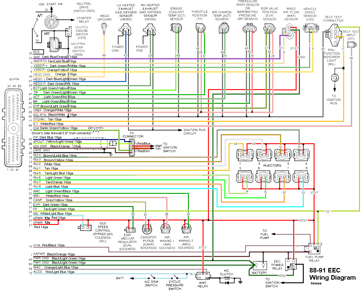
Complete computer, actuator & sensor wiring diagram for 88-91 Mass Air Mustangs
http://www.veryuseful.com/mustang/tech/engine/images/88-91_5.0_EEC_Wiring_Diagram.gif
Complete computer, actuator & sensor wiring diagram for 91-93 Mass Air Mustangs
http://www.veryuseful.com/mustang/tech/engine/images/91-93_5.0_EEC_Wiring_Diagram.gif
Complete computer, actuator & sensor wiring diagram for 94-95 Mass Air Mustangs
http://www.veryuseful.com/mustang/tech/engine/images/94-95_5.0_EEC_Wiring_Diagram.gif
AutoZone wiring diagrams: You can navigate to the diagrams yourself via Repair Info | AutoZone.com and select the car year, make, model and engine. That will enable you to bring up the wiring diagram for your particular car.
2.) Spark at coil wire, pull #1 plug wire off at the spark plug and check to see spark. No spark, possible failed items in order of their probability: [/b]
A.) Moisture inside distributor – remove cap, dry off & spray with WD40
B.) Distributor cap
C.) Rotor
D.) Spark Plug wires
E.) Coil weak or intermittent - you should see 3/8" fat blue spark with a good coil
3.) Spark at spark plug, but no start.
Next, get a can of starting fluid (ether) from your local auto parts store: costs a $1.30 or so. Then pull the air duct off at the throttle body elbow, open the throttle, and spray the ether in it. Reconnect the air duct and try to start the car. Do not try to start the car without reconnecting the air duct.
Two reasons:
1.) If it backfires, the chance for a serious fire is increased.
2.) On Mass Air cars, the computer needs to measure the MAF flow once the engine starts.
If it starts then, you have a fuel management issue. Continue the checklist with emphasis of fuel related items that follow. If it doesn’t, then it is a computer or timing issue: see Step 4.
Clue – listen for the fuel pump to prime when you first turn the ignition switch on. It should run for 2-4 seconds and shut off. To trick the fuel pump into running, find the EEC test connector and jump the connector in the Upper RH corner to ground. The EEC connector is near the wiper motor and LH hood hinge.
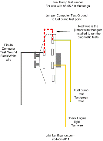
If the relay & inertia switch are OK, you will have power to the pump. Check fuel pressure – remove the cap from the Schrader valve behind the alternator and depress the core. Fuel should squirt out, catch it in a rag. Beware of fire hazard when you do this. In a pinch, you can use a tire pressure gauge to measure the fuel pressure. It may not be completely accurate, but you will have some clue as to how much pressure you have. If you have any doubts about having sufficient fuel flow/pressure, rent a fuel pressure test gauge from the auto parts store. That will tell you for sure if you have adequate fuel pressure.
4.) No fuel pressure, possible failed items in order of their probability:
A.) Tripped inertia switch – Coupe & hatch cars hide it under the plastic trim covering the driver's side taillight. Use the voltmeter or test light to make sure you have power to both sides of the switch
B.) Fuel pump power relay – located under the driver’s seat in most stangs built before 92. On 92 and later model cars it is located below the Mass Air Flow meter. Look for 12 volts at the Pink/Black wire on the fuel pump relay.
C.) Clogged fuel filter
D.) Failed fuel pump
E.) 86-90 models only: Blown fuse link in wiring harness. Look for 12 volts at the Orange/Lt Blue wire on the fuel pump relay.
91-93 models only Blown fuse link in wiring harness. Look for 12 volts at the Pink/Black wire on the fuel pump relay.
The fuse links for all model years 86-93 live in the wiring harness near the starter solenoid.
94-95 models only: 20 amp fuel pump fuse in the engine compartment fuse box. Look for 12 volts at the Dark green/yellow wire on the constant control relay module.
F.) Engine seem to load up on fuel and may have black smoke at the tailpipe. Fuel pressure regulator failed. Remove the vacuum line from the regulator and inspect for fuel escaping while the pump is running. If fuel is coming out the vacuum port, the regulator has failed. Check the regulator vacuum line for fuel too. Disconnect it from the engine and blow air though it. If you find gas, the regulator has failed.
5.) Fuel pressure OK, the injectors are not firing.
A.) The PIP sensor in the distributor tells the computer when to fire the injectors. A failing PIP sensor will sometimes let the engine start if the SPOUT is removed.
A noid light available from any auto parts store, is one way to test the injector circuit to see if the injectors are firing. The noid light plugs into the fuel injector harness in place of any easily accessible injector. Plug it in and try to start the engine: it will flash if the injector is firing.
I like to use an old injector with compressed air applied to the injector where the fuel rail would normally connect. I hook the whole thing up, apply compressed air to the injector and stick it in a paper cup of soapy water. When the engine cranks with the ignition switch on, if the injector fires, it makes bubbles. Cheap if you have the stuff laying around, and works good too.
B.) Pull an injector wire connector off and look for 12 volts on the red wire when the ignition switch is on.
C.) No power, then look for problems with the 10 pin connecter (salt & pepper shakers at the rear of the upper manifold).
See the graphic for the 10 pin connector circuit layout.
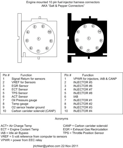
The injector power pin is the VPWR pin in the black 10 pin connector.
D.) No power and the 10 pin connections are good: look for broken wiring between the orange/black wire on the EEC relay and the red wire for the 10 pin connectors.
E.) TPS voltage exceeds 3.7 volts with the throttle closed. This will shut off the injectors, since the computer uses this strategy to clear a flooded engine. Use a DVM, a pair of safety pins, and probe the black/white and green wires to measure the TPS voltage.
On a 94-95 Mustang, probe the black/white and grey/white wires to measure the TPS voltage.
It should be .5-.1.0 volts with the key on, engine not running. Note that if the black/white wire (signal ground) has a bad connection, you will get some strange readings. Make a second measurement using the battery post as the ground to eliminate any ground problems. If the readings are different by more than 5%, you may have a high resistance condition in the black/white signal ground circuit.
6.) Spark & fuel pressure OK.
A.) Failed IAB or improperly set base idle (no airflow to start engine). Press the throttle ¼ way down and try to start the car. See the "Surging Idle Checklist for help with all your idle/stall problems.
B.) Failed computer (not very likely)
C.) Engine ignition or cam timing off: only likely if the engine has been worked on recently. If you removed the distributor, there is a good probability that you installed it 180 degrees out of time.
D.) Firing order off: HO & 351 use a different firing order from the non HO engines.
HO & 351W 1-3-7-2-6-5-4-8
Non HO 1-5-4-2-6-3-7-8
E.) No start when hot - Press the throttle to the floor & try starting it, if you get this far. If it starts, replace the ECT.
F. ) Engine that has had the heads off or valves adjusted. Do a compression test to make sure the valves are not adjusted too tight. You should have a minimum of 90 PSI on a cold engine.
A word about this checklist before you start: it is arranged in a specific order to put the most likely failure items first. That will save you time, energy and money. Start at the top of the list and work your way down. Jumping around will possibly cause you to miss just what you need to see to find and fix the problem. Don’t skip any steps because the next step depends on the last step working correctly.
Revised 15-Sep-2014 to add temporarily bypassing the MSD box if it is present.
All text applies to all models unless stated otherwise.
Note: 94-95 specific changes are in red
1.) Remove push on connector (small red/blue wire) from starter solenoid and turn ignition switch to the Run position. Place car in neutral or Park and set the parking brake. Remove the coil wire from distributor & and hold it 3/8” away from the engine block. Jumper the screw to the big bolt on the starter solenoid that has the battery wire connected to it. You should get a nice fat blue spark.
Most of the items are electrical in nature, so a test light, or even better, a voltmeter, is helpful to be sure they have power to them.
No spark, possible failed items in order of their probability:
A.) MSD, Crane, or other ignition box if present - Bypass it and return to stock configuration if possible. Do this as a temporary measure to eliminate it as a possible problem source.
B.) PIP sensor in distributor. The PIP sensor supplies the timing pulse to trigger the TFI and injectors. A failing PIP sensor will sometimes let the engine start if the SPOUT is removed. See paragraph 5A – Using a noid light will tell if the PIP is working by flashing when the engine is cranking.
C.) TFI module: use a test light to check the TFI module. Place one lead of the test light on the red/green wire on the ignition coil connector and the other lead on the dark green/yellow wire on the ignition coil connector. If the TFI is working properly, the test light will flash when the engine is cranked using the ignition switch.
D.) Coil
E.) No EEC or computer power - EEC or computer relay failure
86-93 models only: EEC relay next to computer - look for 12 volts at the fuel injector red wires.
94-95 models only: EEC or PCM power relay in the constant control relay module. Look for 12 volts at the fuel injector red wires.
Both 86-93 and 94-95 models: No 12 volts with the ignition switch in the run position on the fuel injector red wires. The relay has failed or there is no power coming from the ignition switch. Make sure that there is 12 volts on the red/green wire on the coil before replacing the relay.
F.) No EEC or computer power - fuse or fuse link failure
86-93 models only: Fuse links in wiring harness - look for 12 volts at the fuel injector red wires. All the fuse links live in a bundle up near the starter solenoid. Look for a 20 gauge blue fuse link connected to 2 black/orange 14 gauge wires.
94-95 models only: 20 amp EEC fuse in the engine compartment fuse box. Look for 12 volts at the fuel injector red wires.
G.) Ignition switch - look for 12 volts at the ignition coil red/lt green wire. No 12 volts, blown fuse link or faulty ignition switch. Remove the plastic from around the ignition switch and look for 12 volts on the red/green wire on the ignition switch with it in the Run position. No 12 volts and the ignition switch is faulty. If 12 volts is present in the Run position at the ignition switch but not at the coil, then the fuse or fuse link is blown.
Note: fuses or fuse links blow for a reason. Don’t replace either a fuse or fuse link with one with a larger rating than stock. Doing so invites an electrical fire.
Ignition fuse links may be replaced with an inline fuse holder and 5 amp fuse for troubleshooting purposes.
94-95 models only: Check inside fuse panel for fuse #18 blown – 20 amp [fuse
H.) Missing or loose computer power ground. The computer has its own dedicated power ground that comes off the ground pigtail on the battery ground wire. Due to it's proximity to the battery, it may become corroded by acid fumes from the battery.
In 86-90 model cars, it is a black cylinder about 2 1/2" long by 1" diameter with a black/lt green wire.
In 91-95 model cars it is a black cylinder about 2 1/2" long by 1" diameter with a black/white wire.
You'll find it up next to the starter solenoid where the wire goes into the wiring harness
I.) Computer. Don’t replace the computer just because you don’t understand how it works. Computers seldom fail, it usually is a sensor or wiring problem that causes the problems.
J.) Bad or missing secondary power ground. It is located between the back of the intake manifold and the driver's side firewall. It supplies ground for the alternator, A/C compressor clutch and other electrical accessories such as the gauges.
K.) Engine fires briefly, but dies immediately when the key is released to the Run position. Crank the engine & when it fires off, pull the small push on connector (red/blue wire) off the starter relay (Looks like it is stuck on a screw). Hold the switch in the crank position: if it continues to run there is a problem with either the ignition switch or TFI module. Check for 12 volts at the red/green wire on the coil with the switch in the Run position. Good 12 volts, then replace the TFI. No 12 volts, replace the ignition switch.
Wiring Diagrams:
See the following website for some help from Tmoss (diagram designer) & Stang&2Birds (website host) for help on 88-95 wiring Mustang FAQ - Engine Information Everyone should bookmark this site.
Ignition switch wiring
http://www.veryuseful.com/mustang/tech/engine/images/IgnitionSwitchWiring.gif
Fuel, alternator, A/C and ignition wiring
http://www.veryuseful.com/mustang/tech/engine/images/fuel-alt-links-ign-ac.gif
Complete computer, actuator & sensor wiring diagram for 88-91 Mass Air Mustangs
http://www.veryuseful.com/mustang/tech/engine/images/88-91_5.0_EEC_Wiring_Diagram.gif
Complete computer, actuator & sensor wiring diagram for 91-93 Mass Air Mustangs
http://www.veryuseful.com/mustang/tech/engine/images/91-93_5.0_EEC_Wiring_Diagram.gif
Complete computer, actuator & sensor wiring diagram for 94-95 Mass Air Mustangs
http://www.veryuseful.com/mustang/tech/engine/images/94-95_5.0_EEC_Wiring_Diagram.gif
AutoZone wiring diagrams: You can navigate to the diagrams yourself via Repair Info | AutoZone.com and select the car year, make, model and engine. That will enable you to bring up the wiring diagram for your particular car.
2.) Spark at coil wire, pull #1 plug wire off at the spark plug and check to see spark. No spark, possible failed items in order of their probability: [/b]
A.) Moisture inside distributor – remove cap, dry off & spray with WD40
B.) Distributor cap
C.) Rotor
D.) Spark Plug wires
E.) Coil weak or intermittent - you should see 3/8" fat blue spark with a good coil
3.) Spark at spark plug, but no start.
Next, get a can of starting fluid (ether) from your local auto parts store: costs a $1.30 or so. Then pull the air duct off at the throttle body elbow, open the throttle, and spray the ether in it. Reconnect the air duct and try to start the car. Do not try to start the car without reconnecting the air duct.
Two reasons:
1.) If it backfires, the chance for a serious fire is increased.
2.) On Mass Air cars, the computer needs to measure the MAF flow once the engine starts.
If it starts then, you have a fuel management issue. Continue the checklist with emphasis of fuel related items that follow. If it doesn’t, then it is a computer or timing issue: see Step 4.
Clue – listen for the fuel pump to prime when you first turn the ignition switch on. It should run for 2-4 seconds and shut off. To trick the fuel pump into running, find the EEC test connector and jump the connector in the Upper RH corner to ground. The EEC connector is near the wiper motor and LH hood hinge.
If the relay & inertia switch are OK, you will have power to the pump. Check fuel pressure – remove the cap from the Schrader valve behind the alternator and depress the core. Fuel should squirt out, catch it in a rag. Beware of fire hazard when you do this. In a pinch, you can use a tire pressure gauge to measure the fuel pressure. It may not be completely accurate, but you will have some clue as to how much pressure you have. If you have any doubts about having sufficient fuel flow/pressure, rent a fuel pressure test gauge from the auto parts store. That will tell you for sure if you have adequate fuel pressure.
4.) No fuel pressure, possible failed items in order of their probability:
A.) Tripped inertia switch – Coupe & hatch cars hide it under the plastic trim covering the driver's side taillight. Use the voltmeter or test light to make sure you have power to both sides of the switch
B.) Fuel pump power relay – located under the driver’s seat in most stangs built before 92. On 92 and later model cars it is located below the Mass Air Flow meter. Look for 12 volts at the Pink/Black wire on the fuel pump relay.
C.) Clogged fuel filter
D.) Failed fuel pump
E.) 86-90 models only: Blown fuse link in wiring harness. Look for 12 volts at the Orange/Lt Blue wire on the fuel pump relay.
91-93 models only Blown fuse link in wiring harness. Look for 12 volts at the Pink/Black wire on the fuel pump relay.
The fuse links for all model years 86-93 live in the wiring harness near the starter solenoid.
94-95 models only: 20 amp fuel pump fuse in the engine compartment fuse box. Look for 12 volts at the Dark green/yellow wire on the constant control relay module.
F.) Engine seem to load up on fuel and may have black smoke at the tailpipe. Fuel pressure regulator failed. Remove the vacuum line from the regulator and inspect for fuel escaping while the pump is running. If fuel is coming out the vacuum port, the regulator has failed. Check the regulator vacuum line for fuel too. Disconnect it from the engine and blow air though it. If you find gas, the regulator has failed.
5.) Fuel pressure OK, the injectors are not firing.
A.) The PIP sensor in the distributor tells the computer when to fire the injectors. A failing PIP sensor will sometimes let the engine start if the SPOUT is removed.
A noid light available from any auto parts store, is one way to test the injector circuit to see if the injectors are firing. The noid light plugs into the fuel injector harness in place of any easily accessible injector. Plug it in and try to start the engine: it will flash if the injector is firing.
I like to use an old injector with compressed air applied to the injector where the fuel rail would normally connect. I hook the whole thing up, apply compressed air to the injector and stick it in a paper cup of soapy water. When the engine cranks with the ignition switch on, if the injector fires, it makes bubbles. Cheap if you have the stuff laying around, and works good too.
B.) Pull an injector wire connector off and look for 12 volts on the red wire when the ignition switch is on.
C.) No power, then look for problems with the 10 pin connecter (salt & pepper shakers at the rear of the upper manifold).
See the graphic for the 10 pin connector circuit layout.
The injector power pin is the VPWR pin in the black 10 pin connector.
D.) No power and the 10 pin connections are good: look for broken wiring between the orange/black wire on the EEC relay and the red wire for the 10 pin connectors.
E.) TPS voltage exceeds 3.7 volts with the throttle closed. This will shut off the injectors, since the computer uses this strategy to clear a flooded engine. Use a DVM, a pair of safety pins, and probe the black/white and green wires to measure the TPS voltage.
On a 94-95 Mustang, probe the black/white and grey/white wires to measure the TPS voltage.
It should be .5-.1.0 volts with the key on, engine not running. Note that if the black/white wire (signal ground) has a bad connection, you will get some strange readings. Make a second measurement using the battery post as the ground to eliminate any ground problems. If the readings are different by more than 5%, you may have a high resistance condition in the black/white signal ground circuit.
6.) Spark & fuel pressure OK.
A.) Failed IAB or improperly set base idle (no airflow to start engine). Press the throttle ¼ way down and try to start the car. See the "Surging Idle Checklist for help with all your idle/stall problems.
B.) Failed computer (not very likely)
C.) Engine ignition or cam timing off: only likely if the engine has been worked on recently. If you removed the distributor, there is a good probability that you installed it 180 degrees out of time.
D.) Firing order off: HO & 351 use a different firing order from the non HO engines.
HO & 351W 1-3-7-2-6-5-4-8
Non HO 1-5-4-2-6-3-7-8
E.) No start when hot - Press the throttle to the floor & try starting it, if you get this far. If it starts, replace the ECT.
F. ) Engine that has had the heads off or valves adjusted. Do a compression test to make sure the valves are not adjusted too tight. You should have a minimum of 90 PSI on a cold engine.
This has my mind baffled. I have worked over your post on other Foxbody Mustangs and it has done wonders. Now that it comes to my own car it has my mind blown away.
If all functions are working on car, could a bad ECC Relay cause such a problem with maybe not enough voltage due to it being the original by way of maybe corrosion or pitted coil in relay?

mikestang63
SN Certified Technician
spark or fuel man.. Start with the at the plug and work your way back to the cap, the coil, then through the primary side. Check if you knocked out a wire to the Distributor.
spark or fuel man.. Start with the at the plug and work your way back to the cap, the coil, then through the primary side. Check if you knocked out a wire to the Distributor.[/QUOTE
I do have spark at plugs. The MSD 6AL box when testing through box and coil delivers strong spark. Now here is the kicker. It seemed slow through distributor. It was a MSD distributor, so I sent it back to MSD to be rebuilt and purchased a remanufactured one. Bam, same thing.So that rules out the norms of TFI module or pickup coil. I have never seen one cut off by unplugging the spout to set timing.
Did you do the checklist or just look and it and decide that it was too much trouble. The answer is in there, start at the top and work your way down, do not skip any steps.
I can almost recite this checklist. I have worked on Foxbody Mustangs since new.lol That checklist has been performed many times on many cars. All leading to sucess. This time I'm not having any luck. I have had other ppl look at car as well. One very well known shop, notorious for building some bad rides and they said they don't know. Only thing that hasnt been replaced and I have never had to replace one.
Is the ECMI can almost recite this checklist. I have worked on Foxbody Mustangs since new.lol That checklist has been performed many times on many cars. All leading to sucess. This time I'm not having any luck. I have had other ppl look at car as well. One very well known shop, notorious for building some bad rides and they said they don't know. Only thing that hasnt been replaced and I have never had to replace one.
Awesome breakdown of list. It has helped me many times. Almost feel like I'm talking to a legend.Did you do the checklist or just look and it and decide that it was too much trouble. The answer is in there, start at the top and work your way down, do not skip any steps.
mikestang63
SN Certified Technician

Stock one in there right now, out of a running 5.0. Just swapped one in to see if I might have got a junk one from parts store.swap in a stock ford distributor
So going back through list again. When I hooked up stock ignition and cranked it over, I noticed the tachometer spun backwards. Hooked up MSD again and it just went up with RPMs of trying to crank normally. Any ideas???
Do you have injector pulse?
Fuel injectors inoperative, one or more injectors either on all the time or will not squirt.
Revised 1-Jun-2014 to add computer connector pinout graphic and revise injector wiring resistance readings
Tools needed: Noid light, Multimeter (volts & ohms), 10 MM socket &
extension, & ratchet.
Note: Do all of the steps and do them in order. The results of the subsequent tests are based on the prior tests being successfully passed.
1.) Each injector has a red power wire to provide power to the injector. Turn the ignition switch to Run and remove each injector electrical connector and use the multimeter to check for 12 volts on the red wire. Each injector should have 12 volts +/- .5 volt. More voltage is always better than less voltage. No 12 volts on a singe injector and the wiring for that injector is broken inside the engine fuel injector harness.
No 12 volts on all injectors:
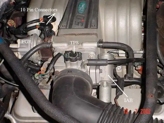
A.) Check for a bad connection at the 10 pin connector. Check for 12 volts at red wire on the MAF or TAD/TAB solenoids mounted on the aft side of the passenger strut tower. Good 12 volts there and you have a wiring problem with the 10 pin connectors or associated wiring.
See the graphic for the location of the 10 pin connectors:
See the graphic for the 10 pin connector circuit layout.
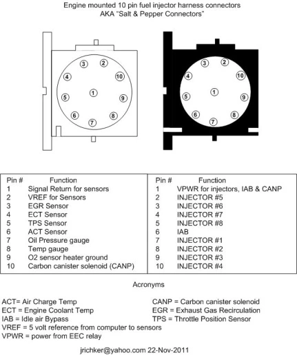
The injector power pin is the VPWR pin in the black 10 pin connector.
B.) Bad ECC power relay. The relay is on top of the computer, it provides power to the fuel injector system. This is relevant ONLY if you do not have power to all injectors.
It is somewhat difficult to get to, since it requires you to remove the computer from its 2 bolt mounting.. If the relay or socket is bad, you will not have 12 volts on any of the red wires in the engine compartment or to pins 37/57 on the computer. The pins 37/57 are the main power feed to the computer.
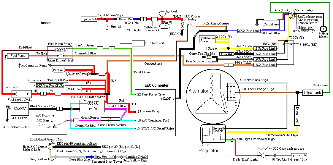
C.) Blown fuse link – The blue fuse link for the computer is up near the starter solenoid. Check for no 12 volts on the ECC relay socket or computer black/orange wires. No 12 volts and the fuse link is blown open. If the fuse link blows, there is no power for any of the computer functions.
D.) Bad wiring. Broken or damaged red wire to the chassis side of the 10 pin connectors.
Some basics about the computer:
Remember that the computer does not supply power for any actuator or relay. It provides the ground necessary to complete the circuit. That means one side of the circuit will always be hot, and the other side will go to ground or below 1 volt as the computer switches on that circuit.
2.) Get a noid light from AutoZone or other auto parts store, or even better a set of them.
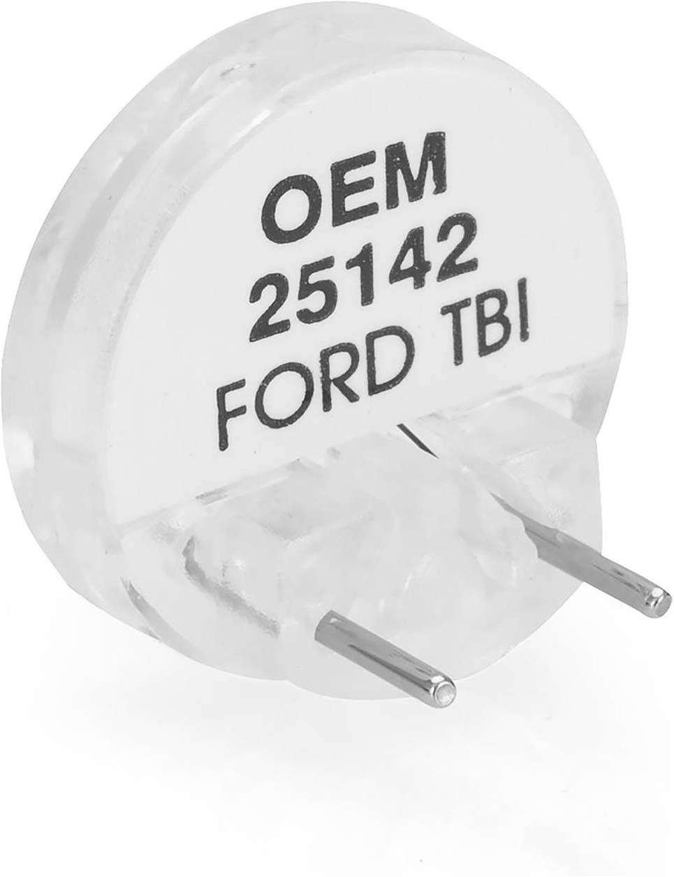
This one is from http://www.summitracing.com/parts/oes-25142?seid=srese1&gclid=CMXk7M6dmM0CFdgOgQodGUMHWQ and costs about $6.
3.) Use the noid light to determine that the injector pulses and isn’t stuck in the on position.
It you have a set of them install all of them and compare the pulse intensity. Install the noid lights, turn the ignition switch to Run and crank the engine. A light that doesn’t pulse and stays on has a short to ground in the computer side of the circuit. That can be either a wiring fault or a failed computer.
If this is the case, remove the passenger side lick panel and disconnect the computer connector.
There is one 10 MM bolt holding it in place. Pull the connector all the way out of the computer so that you can see the computer side pins.
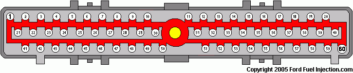
Use the list from the graphic below to find the fuel injector pins for the injectors that didn’t turn the noid light off.
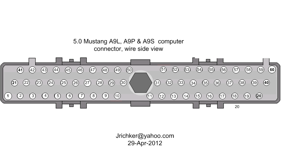
4.) Set the multimeter to low scale Ohms and measure between the computer ground located below the computer and the suspect fuel injector pins. You should see greater than 100 K Ohms resistance. If you see less than 100K Ohms, the wiring between the injector and the computer has an internal short to ground and needs service.
Check the harness and look for damage, kinks or frayed spots.
5.) A single noid light that never turns on is either a wiring fault, or a failed computer. Either the injector has no DC power or the computer has failed and cannot switch the injector circuit to ground. Determine if the injector has power by using the multimeter to check for 12 volts on the red wire on the suspect injector connector. No 12 volts and you have a wiring fault.
Check the harness and look for damage, kinks or frayed spots. Check the 10 pin salt & pepper shaker connectors for bent pins, corrosion and damage.
If none of the noid lights flash and you have 12 volts at each injector, check to see that you have good spark. Before you even think about replacing the computer, see step 6.
Next check the fuel injector wiring end to end. Each fuel injector has a red wire (power) and an non-read wire (computer controlled ground). Set the multimeter to low ohms and measure each non red fuel injector wire from
the fuel injector connector to the matching pin on the computer connector. You should see less than 1 Ohm. More than that means a bad connection or bad wiring.
6.) Use an ohmmeter set on the low resistance scale and measure the resistance of each injector across the two contacts inside the electrical connector. You should see between 11-16 ohms. More or less than that is a bad injector. Next measure between either one of the contacts and the metal on the injector body. You should see greater than 100,000 ohms. Don’t hold the metal probe tips with your bare hands when you make this measurement. It will give incorrect results if you do.
Once you have determined that the suspect injectors have good power and good wiring, the computer is the likely suspect, since a ground is required to complete a circuit and make it function. The computer provides the ground: if doesn’t, then the noid light will not flash. If the noid light stays on, the computer has an internal failure.
7) If you have gotten this far, then the problem is likely ignition related. Remember the noid test using all of the noid lights? All of them were supposed to be equally bright. Since you have already tested all the electrical side of the fuel injector circuit, the one remaining common item is the pip sensor inside the distributor. A failing pip sensor, damaged shutter wheel or bent distributor shaft could all cause the pulse delivered to the injectors to be faulty. A bad pip sensor will cause all the injectors not to fire and you will have no spark. Dumping the codes will usually show a code 14.
8) Spark plugs indicate one or more cylinders not firing: use the multimeter to measure the resistance of the spark plug wires. The wires should measure 2000 ohms per foot of length. A 2 foot wire would be 4000 ohms and a 3 foot wire would be 6000 ohms. Some Taylor and Accel wires have metal cores and will measure much less: that’s OK.
Next examine the spark plug wires very carefully for burn spots, cracks and damaged insulation. One good thing to try is to start the engine while the car is a very dark area, open the hood and look for sparks or blue glow. They indicate the electricity is leaking out of the spark plug wires.
Thanks to Tmoss & Stang&2birds at www.veryuseful.com/mustang/tech/engine/ for some of the graphics
Thanks also to www.oldfuelinjection.com for some of the graphics.
Fuel injectors inoperative, one or more injectors either on all the time or will not squirt.
Revised 1-Jun-2014 to add computer connector pinout graphic and revise injector wiring resistance readings
Tools needed: Noid light, Multimeter (volts & ohms), 10 MM socket &
extension, & ratchet.
Note: Do all of the steps and do them in order. The results of the subsequent tests are based on the prior tests being successfully passed.
1.) Each injector has a red power wire to provide power to the injector. Turn the ignition switch to Run and remove each injector electrical connector and use the multimeter to check for 12 volts on the red wire. Each injector should have 12 volts +/- .5 volt. More voltage is always better than less voltage. No 12 volts on a singe injector and the wiring for that injector is broken inside the engine fuel injector harness.
No 12 volts on all injectors:
A.) Check for a bad connection at the 10 pin connector. Check for 12 volts at red wire on the MAF or TAD/TAB solenoids mounted on the aft side of the passenger strut tower. Good 12 volts there and you have a wiring problem with the 10 pin connectors or associated wiring.
See the graphic for the location of the 10 pin connectors:
See the graphic for the 10 pin connector circuit layout.
The injector power pin is the VPWR pin in the black 10 pin connector.
B.) Bad ECC power relay. The relay is on top of the computer, it provides power to the fuel injector system. This is relevant ONLY if you do not have power to all injectors.
It is somewhat difficult to get to, since it requires you to remove the computer from its 2 bolt mounting.. If the relay or socket is bad, you will not have 12 volts on any of the red wires in the engine compartment or to pins 37/57 on the computer. The pins 37/57 are the main power feed to the computer.
C.) Blown fuse link – The blue fuse link for the computer is up near the starter solenoid. Check for no 12 volts on the ECC relay socket or computer black/orange wires. No 12 volts and the fuse link is blown open. If the fuse link blows, there is no power for any of the computer functions.
D.) Bad wiring. Broken or damaged red wire to the chassis side of the 10 pin connectors.
Some basics about the computer:
Remember that the computer does not supply power for any actuator or relay. It provides the ground necessary to complete the circuit. That means one side of the circuit will always be hot, and the other side will go to ground or below 1 volt as the computer switches on that circuit.
2.) Get a noid light from AutoZone or other auto parts store, or even better a set of them.
This one is from http://www.summitracing.com/parts/oes-25142?seid=srese1&gclid=CMXk7M6dmM0CFdgOgQodGUMHWQ and costs about $6.
3.) Use the noid light to determine that the injector pulses and isn’t stuck in the on position.
It you have a set of them install all of them and compare the pulse intensity. Install the noid lights, turn the ignition switch to Run and crank the engine. A light that doesn’t pulse and stays on has a short to ground in the computer side of the circuit. That can be either a wiring fault or a failed computer.
If this is the case, remove the passenger side lick panel and disconnect the computer connector.
There is one 10 MM bolt holding it in place. Pull the connector all the way out of the computer so that you can see the computer side pins.
Use the list from the graphic below to find the fuel injector pins for the injectors that didn’t turn the noid light off.
4.) Set the multimeter to low scale Ohms and measure between the computer ground located below the computer and the suspect fuel injector pins. You should see greater than 100 K Ohms resistance. If you see less than 100K Ohms, the wiring between the injector and the computer has an internal short to ground and needs service.
Check the harness and look for damage, kinks or frayed spots.
5.) A single noid light that never turns on is either a wiring fault, or a failed computer. Either the injector has no DC power or the computer has failed and cannot switch the injector circuit to ground. Determine if the injector has power by using the multimeter to check for 12 volts on the red wire on the suspect injector connector. No 12 volts and you have a wiring fault.
Check the harness and look for damage, kinks or frayed spots. Check the 10 pin salt & pepper shaker connectors for bent pins, corrosion and damage.
If none of the noid lights flash and you have 12 volts at each injector, check to see that you have good spark. Before you even think about replacing the computer, see step 6.
Next check the fuel injector wiring end to end. Each fuel injector has a red wire (power) and an non-read wire (computer controlled ground). Set the multimeter to low ohms and measure each non red fuel injector wire from
the fuel injector connector to the matching pin on the computer connector. You should see less than 1 Ohm. More than that means a bad connection or bad wiring.
6.) Use an ohmmeter set on the low resistance scale and measure the resistance of each injector across the two contacts inside the electrical connector. You should see between 11-16 ohms. More or less than that is a bad injector. Next measure between either one of the contacts and the metal on the injector body. You should see greater than 100,000 ohms. Don’t hold the metal probe tips with your bare hands when you make this measurement. It will give incorrect results if you do.
Once you have determined that the suspect injectors have good power and good wiring, the computer is the likely suspect, since a ground is required to complete a circuit and make it function. The computer provides the ground: if doesn’t, then the noid light will not flash. If the noid light stays on, the computer has an internal failure.
7) If you have gotten this far, then the problem is likely ignition related. Remember the noid test using all of the noid lights? All of them were supposed to be equally bright. Since you have already tested all the electrical side of the fuel injector circuit, the one remaining common item is the pip sensor inside the distributor. A failing pip sensor, damaged shutter wheel or bent distributor shaft could all cause the pulse delivered to the injectors to be faulty. A bad pip sensor will cause all the injectors not to fire and you will have no spark. Dumping the codes will usually show a code 14.
8) Spark plugs indicate one or more cylinders not firing: use the multimeter to measure the resistance of the spark plug wires. The wires should measure 2000 ohms per foot of length. A 2 foot wire would be 4000 ohms and a 3 foot wire would be 6000 ohms. Some Taylor and Accel wires have metal cores and will measure much less: that’s OK.
Next examine the spark plug wires very carefully for burn spots, cracks and damaged insulation. One good thing to try is to start the engine while the car is a very dark area, open the hood and look for sparks or blue glow. They indicate the electricity is leaking out of the spark plug wires.
Thanks to Tmoss & Stang&2birds at www.veryuseful.com/mustang/tech/engine/ for some of the graphics
Thanks also to www.oldfuelinjection.com for some of the graphics.
Last edited:
mikestang63
SN Certified Technician
So going back through list again. When I hooked up stock ignition and cranked it over, I noticed the tachometer spun backwards. Hooked up MSD again and it just went up with RPMs of trying to crank normally. Any ideas???
Are your coil wires connected backwards? The car will still run, but not as well.

If its lack of fuel causing the problem, shoot some starting fluid into the intake and see if it fires. That can verify a fuel problem sometimes.
So update on car. I have injector pulse and MSD is hooked up correctly. This is the wildest thing ever. I really appreciate the help and ideas. And just tried starter fluid again. No luck. The motor does sound like it wants to hit one time every so many turns over.
mikestang63
SN Certified Technician
When I do the Tach spins backwards. Now I just unplugged at plug and switched stock plugin to coil.have you unhooked the MSD box and wired the coil directly to the harness
Similar threads
- Replies
- 10
- Views
- 330


- Replies
- 6
- Views
- 209
- Replies
- 8
- Views
- 298

- Replies
- 2
- Views
- 593