Calibrated Maf Question

Edward P. Gary

New Member
Jul 23, 2015
1
0
1
Hey, old member with new account and getting back in the mode of Mustang mods. I have a 1990 GT with 24# injectors. I decided to upgrade my old C&L MAF to a calibrated BBK unit with the install of a new cold air intake. The car is running great (swapped out some faulty sensors while I was under the hood), better than ever actually. Idle and horses are sweet.

Anyway, after a bit of a test drive, I threw a check engine light. One of the codes I pulled was 66 (low voltage to MAF). I didn't appear to have this before the new MAF, so my question is this: does the car need to be tuned in order for the A9L to properly work with this setup? I had a dyno tune in the works already, but don't want to bring the car in with malfunctioning sensors, unless that would correct the problem.

Thank you!
 
  • Sponsors (?)


Hey, old member getting back in the mode of Mustang mods. I have a 1990 GT with 24# injectors. I decided to upgrade my old C&L MAF to a calibrated BBK unit with the install of a new cold air intake. The car is running great (swapped out some faulty sensors while I was under the hood), better than ever actually. Idle and horses are sweet.

Anyway, after a bit of a test drive, I threw a check engine light. One of the codes I pulled was 66 (low voltage to MAF). I didn't appear to have this before the new MAF, so my question is this: does the car need to be tuned in order for the A9L to properly work with this setup? I had a dyno tune in the works already, but don't want to bring the car in with malfunctioning sensors, unless that would correct the problem.

Thank you!
 
Code 66 or 157 MAF below minimum test voltage.

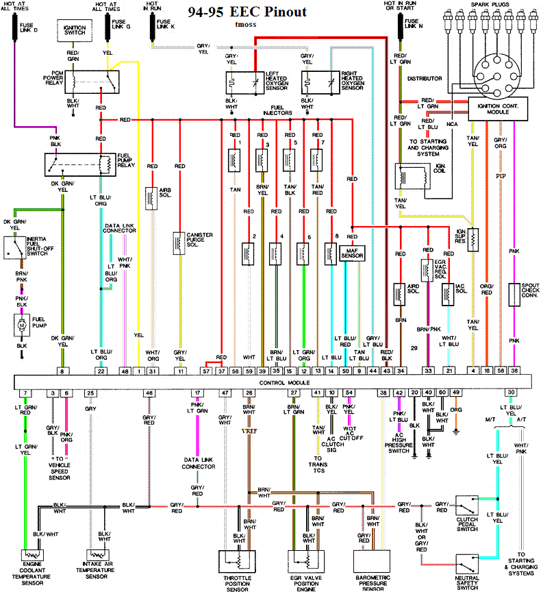
Revised 10-Feb-2014 to add 95-95 Mustang code 157 and 94-95 ECC diagram

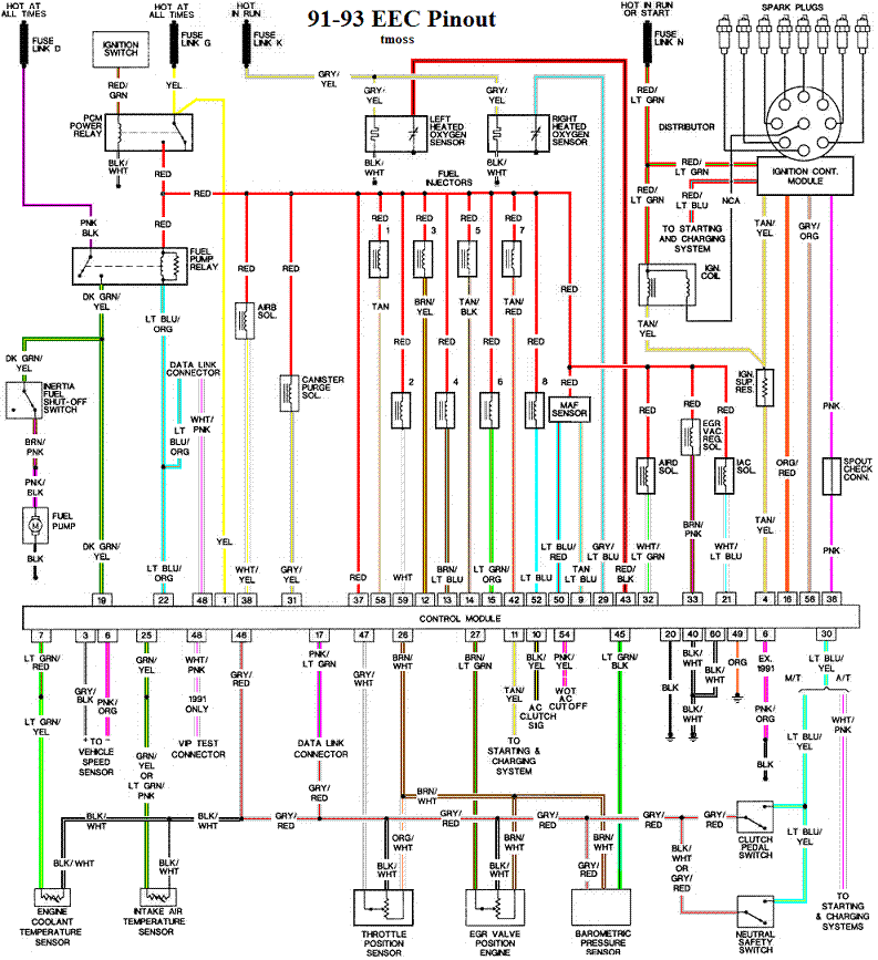
Insufficient or no voltage from MAF. Dirty MAF element, bad MAF, bad MAF wiring, missing power to MAF. Check for missing +12 volts on this circuit. Check the two links for a wiring diagram to help you find the red wire for computer power relay switched +12 volts. Check for 12 volts between the red and black wires on the MAF heater (usually pins A & B). while the connector is plugged into the MAF. This may require the use of a couple of safety pins to probe the MAF connector from the back side of it.

Computer connector for 88-93 5.0 Mustangs
a9x-series-computer-connector-wire-side-view-gif.71316

Diagrams courtesy of Tmoss and Stang&2Birds

ECC Diagram for 88-90 5.0 Mustangs
88-91_5.0_EEC_Wiring_Diagram.gif


ECC Diagram for 91-93 5.0 Mustangs
91-93_5.0_EEC_Wiring_Diagram.gif


94-95 Diagram for 94-95 5.0 Mustangs

94-95_5.0_EEC_Wiring_Diagram.gif


There are three parts in a MAF: the heater, the sensor element and the amplifier. The heater heats the MAF sensor element causing the resistance to increase. The amplifier buffers the MAF output signal and has a resistor that is laser trimmed to provide an output range compatible with the computer's load tables. Changes in RPM causes the airflow to increase or decrease, changing the voltage output.. The increase of air across the MAF sensor element causes it to cool, allowing more voltage to pass and telling the computer to increase the fuel flow. A decrease in airflow causes the MAF sensor element to get warmer, decreasing the voltage and reducing the fuel flow.

The MAF element is secured by 2 screws & has 1 wiring connector. To clean the element, remove it from the MAF housing and spray it down with electronic parts cleaner or non-inflammable brake parts cleaner (same stuff in a bigger can and cheaper too).

89-90 Model cars: Measure the MAF output at pins C & D on the MAF connector (dark blue/orange and tan/light blue) or at pins 50 & 9 on the computer. Be sure to measure the sensor output by measuring across the pins and not between the pins and ground.

91-95 Model cars: Measure the MAF output at pins C & D on the MAF connector light blue/red and tan/light blue) or at pins 50 & 9 on the computer. Be sure to measure the sensor output by measuring across the pins and not between the pins and ground.


At idle = approximately .6 volt
20 MPH = approximately 1.10 volt
40 MPH = approximately 1.70 volt
60 MPH = approximately 2.10 volt

Check the resistance of the MAF signal wiring. Pin D on the MAF and pin 50 on the computer (dark blue/orange wire) should be less than 2 ohms. Pin C on the MAF and pin 9 on the computer (tan/light blue wire) should be less than 2 ohms.

There should be a minimum of 10K ohms between either pin C or D on the MAF wiring connector and pins A or B. Make your measurement with the MAF disconnected from the wiring harness.

Actually MAF pins C & D float with reference to ground. The signal output of the MAF is a differential amplifier setup. Pins C & D both carry the output signal, but one pin's output is inverted from the other. The difference in signal between C & D is what the computer's input circuit is looking for. The difference in the two outputs helps cancel out electrical noise generated by the ignition system and other components. Since the noise will be of the same polarity, wave shape and magnitude, the differential input of the computer electronically subtracts it from the signal. Then it passes the signal on to an Analog to Digital converter section inside the computer's CPU chip.

See the following website for some help from Tmoss (diagram designer) & Stang&2Birds (website host) for help on 88-95 wiring http://www.veryuseful.com/mustang/tech/engine/

Ignition switch wiring
http://www.veryuseful.com/mustang/tech/engine/images/IgnitionSwitchWiring.gif

Fuel pump, alternator, ignition & A/C wiring
http://www.veryuseful.com/mustang/tech/engine/images/fuel-alt-links-ign-ac.gif

Computer,. actuator & sensor wiring
http://www.veryuseful.com/mustang/tech/engine/images/88-91_5.0_EEC_Wiring_Diagram.gif

Fuse panel layout
http://www.veryuseful.com/mustang/tech/engine/images/MustangFuseBox.gif

Vacuum routing
http://www.veryuseful.com/mustang/tech/engine/images/mustangFoxFordVacuumDiagram.jpg
 
Hey, old member with new account and getting back in the mode of Mustang mods. I have a 1990 GT with 24# injectors. I decided to upgrade my old C&L MAF to a calibrated BBK unit with the install of a new cold air intake. The car is running great (swapped out some faulty sensors while I was under the hood), better than ever actually. Idle and horses are sweet.

Anyway, after a bit of a test drive, I threw a check engine light. One of the codes I pulled was 66 (low voltage to MAF). I didn't appear to have this before the new MAF, so my question is this: does the car need to be tuned in order for the A9L to properly work with this setup? I had a dyno tune in the works already, but don't want to bring the car in with malfunctioning sensors, unless that would correct the problem.

Thank you!

Considering that you didn't have the code with the factory meter, the low voltage code would leave me to believe you have a defective MAF sensor. Unfortunately this does happen.
 
Okay, so I went back under the hood, reset the the computer, then adjusted the TPS (I was getting a code for that as well). Took the car for a good test run and put it through the motions, it's still running better than ever. No check engine lights, but I ran diag's anyway just for giggles. I'm now getting codes 85 and 67, nothing else. I read that 85 is the charcoal canister, which I don't have connected. I'm just curious if I screwed something up while adjusting the TPS or should I drive the car some more to see if any CEL's come back? I'm not understanding why these codes would suddenly appear when they weren't just the other day.
 
Code 85 is the charcoal canister, and if it's gone, then that's why you have a code for it.

Code 67 is for the neutral Gear circuit. Either the clutch wasn't pressed in during the test procedure, or the T-5 wasn't in neutral. If either of those two conditions were met, then you either have a wiring issue, or the sensor on top of the t5 is failed.

A code 67 won't allow you to proceed to the engine running codes.
 
I don't believe you need to. The TPS is baselined each time the car is started. Any value between 0.5 and 1.19 volts is in spec.
The RATCH function on the TPS signal only looks for lower values than the current 'idle' RATCH. If the TPS is changed to a higher baseline voltage, then the ecu won't acknowledge it correctly.
It's always better to just reset the ecu...