Would this cause my turn signals and ac blower not to work ?
@madmike1157 Please merge this guy's multiple threads together into one thread.
@Southport2014
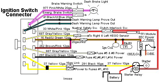
It is the ignition switch wiring connector. The power for everything that needs the ignition switch to be in the Run position goes through it. That includes the turn signals and A/C blower. The Ignition switch is also suspect.
Diagrams courtesy of Tmoss & Stang&2birds
Ignition switch wiring
Some of the symptoms of ignition switch problems are things that don’t work or are intermittent like radio, turn signals, wipers or heater. The auto parts stores sell the switches for $13-$15.
While you are working on the switch, check the wiring and connector closely. A replacement connector with new wiring pigtails is available from most auto parts stores
AutoZone and Advanced Auto Parts have the same Part Number: 434 - may have to order, not always in stock
Advanced Auto Parts alternate part number: PT5534
If just the plastic shell is broken, a small jewelers screwdriver inserted from the front will release the contacts from the connector shell. Do this one wire at time and insert the wire and connector you removed into the same position on the replacement connector shell.
Saleen0679 was nice enough to dig this up for us awhile back: Replace a 1979-1993 Ignition Switch Assembly
Torx bit set from Advance Auto Parts
Autocraft torx bit set – have small hole in tip for tamper proof screws.
Part No. AC571/W1386 Cost approx. $12 +tax
You really need to look at the links I posted. to Mustang FAQ - Wiring & Engine Info If you did, you would have figure all this out very quickly. I will post the links one more time. I will politely tell you to look at them before you make another post. I am not here to spoon feed answers to people, but to give them tools to enable the to do the task at hand and to help them think about what they see, hear and feel. In other words, observe, think about what you observed and diagnose!
See the following website for some help from Tmoss (diagram designer) & Stang&2Birds (website host) for help on 88-95 wiring
Mustang FAQ - Wiring & Engine Info Everyone should bookmark this site.
94-95 Mustang wiring diagrams
Mustang FAQ - Wiring & Engine Info
Complete computer, actuator & sensor wiring diagram for 91-93 Mass Air Mustangs
http://www.veryuseful.com/mustang/tech/engine/images/91-93_5.0_EEC_Wiring_Diagram.gif
Complete computer, actuator & sensor wiring diagram for 88-91 Mass Air Mustangs
http://www.veryuseful.com/mustang/tech/engine/images/88-91_5.0_EEC_Wiring_Diagram.gif
Ignition switch wiring
http://www.veryuseful.com/mustang/tech/engine/images/IgnitionSwitchWiring.gif
Fuel, alternator, A/C and ignition wiring
http://www.veryuseful.com/mustang/tech/engine/images/fuel-alt-links-ign-ac.gif
O2 sensor wiring harness
http://www.veryuseful.com/mustang/tech/engine/images/mustangO2Harness.gif
Vacuum diagram 89-93 Mustangs
http://www.veryuseful.com/mustang/tech/engine/images/mustangFoxFordVacuumDiagram.jpg
HVAC vacuum diagram
http://www.veryuseful.com/mustang/tech/engine/images/Mustang_AC_heat_vacuum_controls.gif
TFI module differences & pin out
http://www.veryuseful.com/mustang/tech/engine/images/TFI_5.0_comparison.gif
Fuse box layout
http://www.veryuseful.com/mustang/tech/engine/images/MustangFuseBox.gif
Mustang 5.0 Lights and Radio schematic, by TMoss:
http://www.veryuseful.com/mustang/tech/engine/images/mustangFoxLights-Radio_diag.gif
87-92 power window wiring
http://www.veryuseful.com/mustang/tech/engine/images/mustang87-92 PowerWindowWiring.gif
93 power window wiring
http://www.veryuseful.com/mustang/tech/engine/images/mustang93PowerWindows.gif
T5 Cutaway showing T5 internal parts
http://www.veryuseful.com/mustang/tech/engine/images/5_Speed_Cutaway_Illustrated.jpg
Visual comparison of the Ford Fuel Injectors, picture by TMoss:
http://www.veryuseful.com/mustang/tech/engine/images/Ford_Injector_Guide.jpg
Convertible top motor wiring
http://www.veryuseful.com/mustang/tech/engine/images/mustang88VertTopMotorCkt.gif
Engine mounted fuel injector harness
http://www.veryuseful.com/mustang/tech/engine/images/mustangEngineHarness.gif tang/tech/engine/images/mustang88VertTopMotorCkt.gif
 20151109_161135.jpg85.4 KB · Views: 170
 20151109_161117.jpg90.8 KB · Views: 168
 20151109_161107.jpg99.9 KB · Views: 164
 20151109_161052.jpg59.7 KB · Views: 156
 20151109_161001.jpg120.7 KB · Views: 147
 20151109_160954.jpg100.5 KB · Views: 176
 20151109_160929_001.jpg107.5 KB · Views: 124
 20151109_160906.jpg125.6 KB · Views: 147
 20151109_160834.jpg81.2 KB · Views: 148
 20151109_160744.jpg109 KB · Views: 130


