
I have a 90 GT Convertible Auto. I have recently received the 44/94 codes (also a 35), but focused on the air codes first. I have vacuum to the TAB/TAD solenoids. I have power to them, and tested the grounding of the TAB. When I ground the TAB solenoid, I do get vacuum to the valve and it opens (so, it can't be the valve either) and I feel air at the hose. I am assuming it is not a ground issue or I would have issues with many sensors (bad assumption?). I also made the assumption that it must be the TPS as this is what controls the opening and closing of the TAB solenoid. I tested the voltage on the grn wire at the TPS, and it was fine (.8 at idle position and 3.6 at WOT). Can someone tell me what else would cause my TAB not to open? Also, made the assumption that my entire issue as at the TAB and once I resolve that the TAD will work also. When I was measuring the WOT voltage, I also had a test light on the TAB solenoid, and when I was at WOT, the light remained on the entire time indicating no change in voltage as I was expecting Anyone experience the same? Anxious to hear. Thx!
You are using an out of date browser. It may not display this or other websites correctly.
You should upgrade or use an alternative browser.
You should upgrade or use an alternative browser.
Engine 90 GT: Cannot resolve codes 44/94
- Thread starter StangsInAZ
- Start date
-
Sponsors (?)
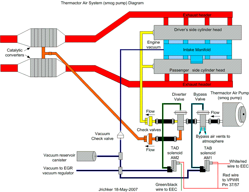
Codes 44 & 94 - AIR system inoperative - Air Injection. Check vacuum lines for leaks, & cracks. Check for a clogged air crossover tube, where one or both sides of the tube clog with carbon.
Revised 21 Sep 2012 to correct the description of the process that sets the code and include Thermactor Air System diagram.
If you have a catalytic converter H pipe, you need to fix these codes. If you don't, then don't worry about them.
Code 44 passenger side air not functioning.
Code 94 driver side air not functioning.
The TAD solenoid/TAD diverter valve directs smog pump output to either the crossover tube attached to the cylinder heads or to the catalytic converters.
The O2 sensors are placed before the catalytic converters, so they do not see the extra O2 when the smog pump's output is directed to the converters or the input just before the converter.
The 44/94 code uses the O2 sensors to detect a shift in the O2 level in the exhaust. The smog pump provides extra air to the exhaust which raises the O2 level in the exhaust when the smog pump output is directed through the crossover tube.
When there is an absence of increase in the O2 levels when the TAD solenoid/TAD diverter valve directs air through the crossover tube, it detects the lower O2 level and sets the code.
Failure mode is usually due to a clogged air crossover tube, where one or both sides of the tube clog with carbon. The air crossover tube mounts on the back of the cylinder heads and supplies air to each of the Thermactor air passages cast into the cylinder heads. When the heads do not get the proper air delivery, they set codes 44 & 94, depending on which passage is clogged. It is possible to get both 44 & 94, which would suggest that the air pump or control valves are not working correctly, or the crossover tube is full of carbon or missing.
Testing the system:
Note that the engine must be running to do the tests unless stated otherwise. For safety’s sake, do test preparation like loosening clamps, disconnecting hoses and connecting things to a vacuum source with the engine off.
Disconnect the big hose from smog pump: with the engine running you should feel air output. Reconnect the smog pump hose & apply vacuum to the first vacuum controlled valve: Its purpose is to either dump the pump's output to the atmosphere or pass it to the next valve.
The next vacuum controlled valve directs the air to either the cylinder heads when the engine is cold or to the catalytic converter when the engine is warm. Disconnect the big hoses from the back side of the vacuum controlled valve and start the engine. Apply vacuum to the valve and see if the airflow changes from one hose to the next.
The two electrical controlled vacuum valves mounted on the rear of the passenger side wheel well turn the vacuum on & off under computer control. Check to see that both valves have +12 volts on the red wire. Then ground the white/red wire and the first solenoid should open and pass vacuum. Do the same thing to the light green/black wire on the second solenoid and it should open and pass vacuum.
Remember that the computer does not source power for any actuator or relay, but provides the ground necessary to complete the circuit. That means one side of the circuit will always be hot, and the other side will go to ground or below 1 volt as the computer switches on that circuit.
The following computer tests are done with the engine not running.
The computer provides the ground to complete the circuit to power the solenoid valve that turns the
vacuum on or off. The computer is located under the passenger side kick panel. Remove the kick panel & the cover over the computer wiring connector pins. Check Pin 38 Solenoid valve #1 that provides vacuum to the first Thermactor control valve for a switch from 12-14 volts to 1 volt or less. Do the same with pin 32 solenoid valve #2 that provides vacuum to the second Thermactor control valve. Turning the ignition to Run with the computer jumpered to self-test mode will cause all the actuators to toggle on and off. If after doing this and you see no switching of the voltage on and off, you can start testing the wiring for shorts to ground and broken wiring. An Ohm check to ground with the computer connector disconnected & the solenoid valves disconnected should show open circuit between the pin 32 and ground and again on pin 38 and ground. In like manner, there should be less than 1 ohm between pin 32 and solenoid valve #2 and pin 38 & Solenoid valve #1.
The following computer tests are done with the engine running.
If after checking the resistance of the wiring & you are sure that there are no wiring faults, start looking at the solenoid valves. If you disconnect them, you can jumper power & ground to them to verify operation with the engine running. Power & ground supplied should turn on the vacuum flow, remove either one and the vacuum should stop flowing.
Typical resistance of the solenoid valves is in the range of 20-70 Ohms.
See the following website for some help from Tmoss (diagram designer) & Stang&2Birds (website host)
http://www.veryuseful.com/mustang/tech/engine/images/fuel-alt-links-ign-ac.gif
http://www.veryuseful.com/mustang/tech/engine/images/88-91eecPinout.gif
If you have a catalytic converter H pipe, you need to fix these codes. If you don't, then don't worry about them

Thank you for the explanations. I have followed your testing and found that all looks correct as far as vacuum and electric signals and power. I replaced to EVP sensor to fix the code 35 and also replaced the O2 sensors. They were 30 years old anyhow. I put everything back together, and I still have the 44/94, but now I also have 31 instead of 35. I do have a difference though. I know the TAB is working, as I feel air coming from the TAB valve to the hose the goes to the TAD valve. With the engine warm, I have no vacuum at the TAD valve (normal?). What else could be causing my 44/94 codes? Also what would cause 31 now? Thanks!
Went back to the TAD solenoid. It seemed like it was not working right, so replaced that too. After replacing TAD, no more 44/94. Now I am getting 41 and 31, I have replaced the O2 sensors, the EVP, and the TAB/TAD solenoids. I started with codes 44/94/35 to 41/31. Amy ideas why replacing these parts would change my codes to these?
Went back to the TAD solenoid. It seemed like it was not working right, so replaced that too. After replacing TAD, no more 44/94. Now I am getting 41 and 31, I have replaced the O2 sensors, the EVP, and the TAB/TAD solenoids. I started with codes 44/94/35 to 41/31. Amy ideas why replacing these parts would change my codes to these?
Did you clear the codes after replacing the parts?
How to clear codes.
Clearing the codes by pressing a button on the scan tool or disconnecting the test jumper used to start the code dump does not erase the “learned settings”. All it does is erase the stored codes in memory.
You must clear the codes anytime you replace any sensor. The following tells you how and is different from the method above
Clear the computer codes by disconnecting the battery negative terminal and turn the headlights on. Turn the headlights off and reconnect the all sensors including the MAF and anything else you may have disconnected. Then reconnect the battery negative cable.. This clears all spurious codes may have been generated while troubleshooting problems. It also clears the adaptive settings that the computer "learns" as it operates. Clearing the codes does not fix the code problems, it just gives you a clean slate to start recording what the computer sees happening.
Run the car for at least 30 minutes of driving and dump the codes again to assure that you have fixed the code problem or sensor problem. This is necessary for the computer to relearn the adaptive settings that the computer uses for proper operation. The engine may run rough at first, but should smooth out as it runs for the 15-20 minute learning period.
I followed your clear codes and driving instructions. The CEL was on the entire time I was driving. It runs good, just like it did before replacing the sensors. It will not pass emissions with the CEL light on though. I dumped the codes when I got home and had KOEO - 31; KOER - 94/31. I got my ole 94 back. I ran a test on the TAD solenoid again and see that when dumping codes, the voltage remains at 12.4, no dip. I checked from the back of the computer to the solenoid and it has continuity and the Ohms are almost 0. Not sure why the 31. I had a 35 before the EVP sensor change and now the 31. Am I missing something?
Code 94 no change in voltage. Use a test light attached across the TAD solenoid wiring plug. When you turn the ignition to Run and put the tester into scan mode, it toggles all the relays and solenoids. Watch for the test light to flicker briefly when you hear all the relays and solenoid click.
CODE: 31 (KOEO) - EVP circuit below minimum voltage. Vref (5 volt reference voltage supplied by the computer) missing or broken wire or bad connection in circuit.
Revised 06-Aug-2016 to add clarification of the 10 pin connector possible problems
Use a DVM to check for 5 volts on the orange/white wire. If it is missing, look for +5 volts at the orange/white wire on the TPS or MAP sensor located on the firewall near the center of the car. Use the black/white wire for the ground for the DVM.
With the sensor removed from the EGR and still connected, press the plunger and watch the voltage change on the brown/lt green wire. Pull the passenger side kick panel and measure the voltage at the computer. You will need to remove the plastic cover over the wires and probe them from the backside. A safety pin may prove very useful for this task. Use pin 27, EVR input (brown/lt green wire) and pin 46, signal ground (black/white wire) to measure the voltage. The orange/white wire is Vref and should always be 5 volts -/+ .25 volt. Be sure to measure Vref at the EGR sensor to rule out any broken wires or bad connections.
Measuring the voltage at the computer helps you spot broken wiring and intermittent connections. The 10 pin connectors are especially prone to connection problems, If the voltage checks at the EGR sensor are good but not at the computer,
See the graphic for the 10 pin connector circuit layout.

Computer wiring harness connector, wire side

Computer wiring harness connector, computer side

Code 35 EVR - EVP sensor signal is/was high – Bad sensor, or possible missing ground for EVR circuit. With the power off, measure the resistance between the black/white wire and battery ground. You should see less than 1 ohm. Check the same black /white wire on the TPS and MAP sensor. More than 1 ohm there and the wire is probably broken in the harness between the engine and the computer. The 10 pin connectors pass the black/white wire back to the computer, and can cause problems.
See the following website for some help from Tmoss (diagram designer) & Stang&2Birds (website host)
http://www.veryuseful.com/mustang/tech/engine/images/88-91eecPinout.gif
See the graphic for the 10 pin connector circuit layout.

About this time you have noticed that the 10 pin salt & pepper shaker connectors are common to both code 31 & 35. It would be a good idea to clean the connectors and slightly bend the female connector so that it tightly grips the male connector pin.
CODE: 31 (KOEO) - EVP circuit below minimum voltage. Vref (5 volt reference voltage supplied by the computer) missing or broken wire or bad connection in circuit.
Revised 06-Aug-2016 to add clarification of the 10 pin connector possible problems
Use a DVM to check for 5 volts on the orange/white wire. If it is missing, look for +5 volts at the orange/white wire on the TPS or MAP sensor located on the firewall near the center of the car. Use the black/white wire for the ground for the DVM.
With the sensor removed from the EGR and still connected, press the plunger and watch the voltage change on the brown/lt green wire. Pull the passenger side kick panel and measure the voltage at the computer. You will need to remove the plastic cover over the wires and probe them from the backside. A safety pin may prove very useful for this task. Use pin 27, EVR input (brown/lt green wire) and pin 46, signal ground (black/white wire) to measure the voltage. The orange/white wire is Vref and should always be 5 volts -/+ .25 volt. Be sure to measure Vref at the EGR sensor to rule out any broken wires or bad connections.
Measuring the voltage at the computer helps you spot broken wiring and intermittent connections. The 10 pin connectors are especially prone to connection problems, If the voltage checks at the EGR sensor are good but not at the computer,
See the graphic for the 10 pin connector circuit layout.
Computer wiring harness connector, wire side
Computer wiring harness connector, computer side
Code 35 EVR - EVP sensor signal is/was high – Bad sensor, or possible missing ground for EVR circuit. With the power off, measure the resistance between the black/white wire and battery ground. You should see less than 1 ohm. Check the same black /white wire on the TPS and MAP sensor. More than 1 ohm there and the wire is probably broken in the harness between the engine and the computer. The 10 pin connectors pass the black/white wire back to the computer, and can cause problems.
See the following website for some help from Tmoss (diagram designer) & Stang&2Birds (website host)
http://www.veryuseful.com/mustang/tech/engine/images/88-91eecPinout.gif
See the graphic for the 10 pin connector circuit layout.
About this time you have noticed that the 10 pin salt & pepper shaker connectors are common to both code 31 & 35. It would be a good idea to clean the connectors and slightly bend the female connector so that it tightly grips the male connector pin.
I hooked up the test light to the TAD grn wire, and dumped the codes, when I did, I did see the flicker you mention. So, does this mean the new solenoid is bad? It appears all electronic signals are correct.
Similar threads
- Replies
- 1
- Views
- 186
- Replies
- 22
- Views
- 2K
- Replies
- 4
- Views
- 1K
- Replies
- 20
- Views
- 5K
- Replies
- 4
- Views
- 1K