
Hey guys, my 92 5.0 Lx keeps shutting off and I don't know why? It'll start right up and run for about a min or two and slowly starts to die out and then will stall and 90% of the time will not start back up unless you let it sit for a little bit. I've recently changed the following: distributor (advance auto), a9p computer (used from a 90 Lx), iac valve, tps sensor, coil, plugs, fuel filter, fuel pressure regulator, fuel pump and ecc/eec (whatever it's called) relay and cleaned the throttle body and mass air sensor with the appropriate cleaners. Before this happened the car wouldn't run at all till I changed the computer. It ran ok besides an occasional hiccup/miss while driving when it was cold out (mostly happened at night)for about 3 weeks and now this is going on. It seems like it just loses spark or fuel or something. I changed a few of the injectors with factory Ford ones that are 19 lb/hr but weren't fox injectors- they're like a goldish yellow not orange and I tested the fuel pressure at the schrader valve and had 40lbs at the time. Any ideas what could be the cause? Can the fuel pump maybe be dying out even though I can still hear it running? Bad distributor? When I changed the plugs they were very white and lean. Car seems to run fine and have no loss of power for the short period of time it does run, revs fine and everything. Only mods are bbk cai and equal length shorties, upr catless x flowmaster 40's and 373's. I have videos to show what it's doing if I can figure out how to post them
You are using an out of date browser. It may not display this or other websites correctly.
You should upgrade or use an alternative browser.
You should upgrade or use an alternative browser.
92 5.0 Fox Stalls
- Thread starter Stonerboys
- Start date
-
Sponsors (?)
http://forums.stangnet.com/787471-cranks-ok-but-no-start-checklist-fuel-injected-mustangs.html
This is a link to the ' cranks but no start checklist'
It shows you how to check for codes too, read it over once then do it step by step, don't skip around just because you've replaced something.
This is a link to the ' cranks but no start checklist'
It shows you how to check for codes too, read it over once then do it step by step, don't skip around just because you've replaced something.
mikestang63
SN Certified Technician
It starts and runs it just doesn't stay running for very long. I have a code reader and can't get the car to throw any codes. No check engine light either
1.) Are you sure that you connected the code reader up correctly? I highly suggest that you read it and follow the instructions to dump the codes. http://www.stangnet.com/mustang-forums/threads/how-to-pull-codes-from-eec4.889006/
2.) If you did connect the code reader up correctly and still don get codes to dump, here is the next step.
Computer will not go into diagnostic mode on 91-95 model 5.0 Mustangs
Revised 7-June-2014 to change resistance figures to wiring checks
How it is supposed to work:
The grey/red wire (pin 46) is signal ground for the computer. It provides a dedicated ground for the EGR, Baro, ACT, ECT, & TPS sensors as well as the ground to put the computer into self-test mode. As long as you are successful dumping the codes by using the gray/red wire on the diagnostic connector for the ground when dumping, the computer’s internal ground on pin 46 is good.
If this ground is bad, none of the sensors mentioned will work properly. That will severely affect the car's performance. You will have hard starting, low power and drivability problems. Since it is a dedicated ground, it passes through the computer on its way to the computer main power ground that terminates at the battery pigtail ground. It should read less than 1 ohm when measured from anyplace on the engine harness with the battery pigtail ground as the other reference point for the ohmmeter probe.
What sometimes happens is that the test connector grey/red wire gets jumpered to power which either burns up the wiring or burns the trace off the pc board inside the computer. That trace connects pins 46 to pins 40 & 60.
The STI (Self Test Input ) is jumpered to ground to put the computer into test mode. Jumpering it to power can produce unknown results, including damage to the computer. The ohm test simply verifies that there are no breaks in the wiring between the test connector and the computer input.
How to test the wiring :
With the power off, measure the resistance between the computer test ground (grey/red wire) on the self- test connector and battery ground. You should see less than 1 ohm.

If that check fails, remove the passenger side kick panel and disconnect the computer connector. There is a 10 MM bolt that holds it in place. Measure the resistance between the grey/red wire and pin 46 on the computer wiring connector: it should be less than 1 ohm. More than 1 ohm is a wiring problem. If it reads 1 ohm or less, then the computer is suspect. On the computer, measure the resistance between pin 46 and pins 40 & 60: it should be less than 1 ohm. More than that and the computer’s internal ground has failed, and the computer needs to be repaired or replaced.
See http://www.stangnet.com/mustang-forums/749974-computer-issue.html#post7490537 for Joel5.0’s fix for the computer internal signal ground.
If the first ground check was good, there are other wires to check. Measure the resistance between the STI computer self-test connector (red/white wire) and pin 48 on the computer main connector: it should be less than 1.5 ohms. More than 1 ohms is a wiring problem
The following is a view from the computer side of the computer wiring connector: it is for an A9L, A9P computer.

Diagram courtesy of Tmoss & Stang&2birds
Check out the diagram and notice all the places the grey/red wire goes. Almost every sensor on the engine except the MAF is connected to it.
91-93 5.0 Mustangs

Complete computer, actuator & sensor wiring diagram for 94-95 Mass Air Mustangs

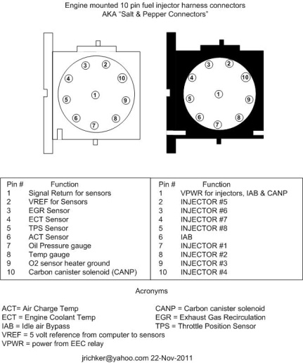
See the graphic for the 10 pin connector circuit layout.
See the following website for some help from Tmoss (diagram designer) & Stang&2Birds
(website host) for help on 88-95 wiring http://www.veryuseful.com/mustang/tech/engine
2.) If you did connect the code reader up correctly and still don get codes to dump, here is the next step.
Computer will not go into diagnostic mode on 91-95 model 5.0 Mustangs
Revised 7-June-2014 to change resistance figures to wiring checks
How it is supposed to work:
The grey/red wire (pin 46) is signal ground for the computer. It provides a dedicated ground for the EGR, Baro, ACT, ECT, & TPS sensors as well as the ground to put the computer into self-test mode. As long as you are successful dumping the codes by using the gray/red wire on the diagnostic connector for the ground when dumping, the computer’s internal ground on pin 46 is good.
If this ground is bad, none of the sensors mentioned will work properly. That will severely affect the car's performance. You will have hard starting, low power and drivability problems. Since it is a dedicated ground, it passes through the computer on its way to the computer main power ground that terminates at the battery pigtail ground. It should read less than 1 ohm when measured from anyplace on the engine harness with the battery pigtail ground as the other reference point for the ohmmeter probe.
What sometimes happens is that the test connector grey/red wire gets jumpered to power which either burns up the wiring or burns the trace off the pc board inside the computer. That trace connects pins 46 to pins 40 & 60.
The STI (Self Test Input ) is jumpered to ground to put the computer into test mode. Jumpering it to power can produce unknown results, including damage to the computer. The ohm test simply verifies that there are no breaks in the wiring between the test connector and the computer input.
How to test the wiring :
With the power off, measure the resistance between the computer test ground (grey/red wire) on the self- test connector and battery ground. You should see less than 1 ohm.
If that check fails, remove the passenger side kick panel and disconnect the computer connector. There is a 10 MM bolt that holds it in place. Measure the resistance between the grey/red wire and pin 46 on the computer wiring connector: it should be less than 1 ohm. More than 1 ohm is a wiring problem. If it reads 1 ohm or less, then the computer is suspect. On the computer, measure the resistance between pin 46 and pins 40 & 60: it should be less than 1 ohm. More than that and the computer’s internal ground has failed, and the computer needs to be repaired or replaced.
See http://www.stangnet.com/mustang-forums/749974-computer-issue.html#post7490537 for Joel5.0’s fix for the computer internal signal ground.
If the first ground check was good, there are other wires to check. Measure the resistance between the STI computer self-test connector (red/white wire) and pin 48 on the computer main connector: it should be less than 1.5 ohms. More than 1 ohms is a wiring problem
The following is a view from the computer side of the computer wiring connector: it is for an A9L, A9P computer.
Diagram courtesy of Tmoss & Stang&2birds
Check out the diagram and notice all the places the grey/red wire goes. Almost every sensor on the engine except the MAF is connected to it.
91-93 5.0 Mustangs
Complete computer, actuator & sensor wiring diagram for 94-95 Mass Air Mustangs
See the graphic for the 10 pin connector circuit layout.
See the following website for some help from Tmoss (diagram designer) & Stang&2Birds
(website host) for help on 88-95 wiring http://www.veryuseful.com/mustang/tech/engine
Shawn Farbman
New Member
- Aug 16, 2017
- 5
- 0
- 1
Jrichker- there's only one way to hook the reader up isn't there? It'll only throw the check engine light when it stalls. As soon as you turn the key off it goes away. I'll have to try checking all of the stuff above when I get the chance sometime this week.
Shawn- my dad put the distributor in that's out of my knowledge range but we checked the timing and it seems fine. The car ran fine for about 3 weeks after I changed that and the computer but it would have a studder/miss at cruising speeds where you could feel the car jolt and the tack would bounce up like 200rpms or so.
Is there a possibility I could have got another bad computer? The original one for the car wouldn't let the fuel pump shut off that's why it wouldn't run before and now the car is goofing up again. I'm going to get my factory computer rebuilt I think because I want to have it working again anyways-any recommendations? Is the rebuild service that Autozone offers through blue streak reputable/any good?
I
Dump the codes: Codes may be present even if the Check Engine Light (CEL) isn't on.
Dumping the computer diagnostic codes on 86-95 Mustangs
Revised 26-July-2011. Added need to make sure the clutch is pressed when dumping codes.
Codes may be present even if the check engine light hasn’t come on, so be sure to check for them.
Here's the way to dump the computer codes with only a jumper wire or paper clip and the check engine light, or test light or voltmeter. I’ve used it for years, and it works great. You watch the flashing test lamp or Check Engine Light and count the flashes.
Post the codes you get and I will post 86-93 model 5.0 Mustang specific code definitions and fixes. I do not have a complete listing for 94-95 model 5.0 Mustangs at this time.
Be sure to turn off the A/C, and put the transmission in neutral when dumping the codes. On a manual transmission car, be sure to press the clutch to the floor.
Fail to do this and you will generate a code 67 and not be able to dump the Engine Running codes.
Foxbody Diagnostic connector
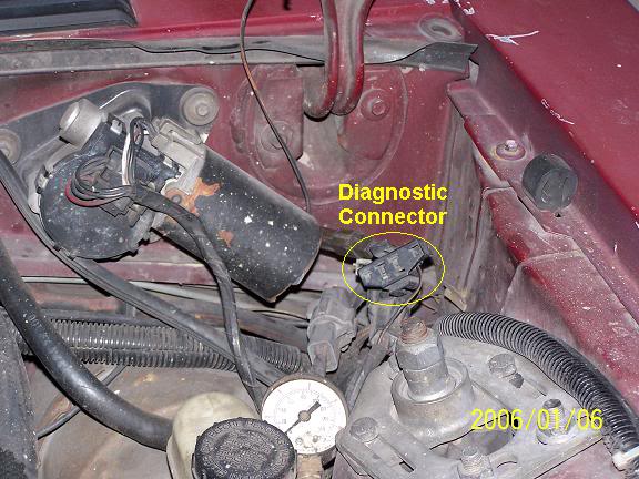
Foxbody Diagnostic connector close up view

If your car is an 86-88 stang, you'll have to use the test lamp or voltmeter method. There is no functional check engine light on the 86-88's except possibly the Cali Mass Air cars.

The STI has a gray connector shell and a white/red wire. It comes from the same bundle of wires as the self test connector.
89 through 95 cars have a working Check Engine light. Watch it instead of using a test lamp.
The STI has a gray connector shell and a white/red wire. It comes from the same bundle of wires as the self test connector.
WARNING!!! There is a single dark brown connector with a black/orange wire. It is the 12 volt power to the under the hood light. Do not jumper it to the computer test connector. If you do, you will damage the computer.
What to expect:
You should get a code 11 (two single flashes in succession). This says that the computer's internal workings are OK, and that the wiring to put the computer into diagnostic mode is good. No code 11 and you have some wiring problems. This is crucial: the same wire that provides the ground to dump the codes provides signal ground for the TPS, EGR, ACT and Map/Baro sensors. If it fails, you will have poor performance, economy and driveablity problems
Some codes have different answers if the engine is running from the answers that it has when the engine isn't running. It helps a lot to know if you had the engine running when you ran the test.
Dumping the Engine Running codes: The procedure is the same, you start the engine with the test jumper in place. Be sure the A/C is off, and clutch (if present) is pressed to the floor, and the transmission is in neutral. You'll get an 11, then a 4 and the engine will speed up to do the EGR test. After the engine speed decreases back to idle, it will dump the engine running codes.
Trouble codes are either 2 digit or 3 digit, there are no cars that use both 2 digit codes and 3 digit codes.
Your 86-88 5.0 won't have a working Check Engine Light, so you'll need a test light.
See AutoZone Part Number: 25886 , $10

Alternate methods:
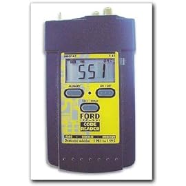
For those who are intimidated by all the wires & connections, see Actron® for what a typical hand scanner looks like. Normal retail price is about $30 or so at AutoZone or Wal-Mart.
Reader/dp/B000EW0KHW Equus - Digital Ford Code Reader 3145.
Or for a nicer scanner see www.midwayautosupply.com/Equus-Digital-Ford-Code-It has a 3 digit LCD display so that you don’t have to count flashes or beeps.. Cost is $22-$36.
Order it at Walmart for a better price and free shipping
There is another way, and it almost always damages the computer. The clue is that It won't dump codes anymore.Jrichker- there's only one way to hook the reader up isn't there? It'll only throw the check engine light when it stalls. As soon as you turn the key off it goes away. I'll have to try checking all of the stuff above when I get the chance sometime this week.
Shawn- my dad put the distributor in that's out of my knowledge range but we checked the timing and it seems fine. The car ran fine for about 3 weeks after I changed that and the computer but it would have a studder/miss at cruising speeds where you could feel the car jolt and the tack would bounce up like 200rpms or so.
Is there a possibility I could have got another bad computer? The original one for the car wouldn't let the fuel pump shut off that's why it wouldn't run before and now the car is goofing up again. I'm going to get my factory computer rebuilt I think because I want to have it working again anyways-any recommendations? Is the rebuild service that Autozone offers through blue streak reputable/any good?
Dump the codes: Codes may be present even if the Check Engine Light (CEL) isn't on.
Dumping the computer diagnostic codes on 86-95 Mustangs
Revised 26-July-2011. Added need to make sure the clutch is pressed when dumping codes.
Codes may be present even if the check engine light hasn’t come on, so be sure to check for them.
Here's the way to dump the computer codes with only a jumper wire or paper clip and the check engine light, or test light or voltmeter. I’ve used it for years, and it works great. You watch the flashing test lamp or Check Engine Light and count the flashes.
Post the codes you get and I will post 86-93 model 5.0 Mustang specific code definitions and fixes. I do not have a complete listing for 94-95 model 5.0 Mustangs at this time.
Be sure to turn off the A/C, and put the transmission in neutral when dumping the codes. On a manual transmission car, be sure to press the clutch to the floor.
Fail to do this and you will generate a code 67 and not be able to dump the Engine Running codes.
Foxbody Diagnostic connector
Foxbody Diagnostic connector close up view
If your car is an 86-88 stang, you'll have to use the test lamp or voltmeter method. There is no functional check engine light on the 86-88's except possibly the Cali Mass Air cars.
The STI has a gray connector shell and a white/red wire. It comes from the same bundle of wires as the self test connector.
89 through 95 cars have a working Check Engine light. Watch it instead of using a test lamp.
The STI has a gray connector shell and a white/red wire. It comes from the same bundle of wires as the self test connector.
WARNING!!! There is a single dark brown connector with a black/orange wire. It is the 12 volt power to the under the hood light. Do not jumper it to the computer test connector. If you do, you will damage the computer.
What to expect:
You should get a code 11 (two single flashes in succession). This says that the computer's internal workings are OK, and that the wiring to put the computer into diagnostic mode is good. No code 11 and you have some wiring problems. This is crucial: the same wire that provides the ground to dump the codes provides signal ground for the TPS, EGR, ACT and Map/Baro sensors. If it fails, you will have poor performance, economy and driveablity problems
Some codes have different answers if the engine is running from the answers that it has when the engine isn't running. It helps a lot to know if you had the engine running when you ran the test.
Dumping the Engine Running codes: The procedure is the same, you start the engine with the test jumper in place. Be sure the A/C is off, and clutch (if present) is pressed to the floor, and the transmission is in neutral. You'll get an 11, then a 4 and the engine will speed up to do the EGR test. After the engine speed decreases back to idle, it will dump the engine running codes.
Trouble codes are either 2 digit or 3 digit, there are no cars that use both 2 digit codes and 3 digit codes.
Your 86-88 5.0 won't have a working Check Engine Light, so you'll need a test light.
See AutoZone Part Number: 25886 , $10
Alternate methods:
For those who are intimidated by all the wires & connections, see Actron® for what a typical hand scanner looks like. Normal retail price is about $30 or so at AutoZone or Wal-Mart.
Reader/dp/B000EW0KHW Equus - Digital Ford Code Reader 3145.
Or for a nicer scanner see www.midwayautosupply.com/Equus-Digital-Ford-Code-It has a 3 digit LCD display so that you don’t have to count flashes or beeps.. Cost is $22-$36.
Order it at Walmart for a better price and free shipping
Ok guys so I got the reader pictured above figured out after playing with it and reading a little bit (probably should have did this in the first place haha) without starting the car I got three codes 81,10,11 10 & 11 which basically just seem to mean all of the electronic stuff is working, so I disconnected the reader and started the car and let it run till it stalled itself out like its been doing. After about a minute or two it stalled, and I reconnected the code reader back up and got these 3 codes: 81,10 and 87. 81-air diverter solenoid fault/intake air control circuit fault/air injection diverter and 87-Fuel Pump Primary circuit fault. Does this mean either the fuel pump relay I bought is bad or is the original fuel pump need replaced? And what does the 81 mean? Thanks in advance for your help!
Code 87 – fuel pump primary circuit failure. The fuel pump lost power while the engine was running. Check fuel pump relay, check inertia switch, wiring to/from inertia switch, red wire going to inertia switch for +12volts. Check the other side of inertia switch for +12 volts.
Diagram of the fuel pump wiring for 91-93 cars.

Fuel Pump Troubleshooting for 91-93 Mustangs
Revised 6-Feb-2016 to add fuse link diagram
Ignition switch in the Run position, engine not running tests.
Clue – listen for the fuel pump to prime when you first turn the ignition switch on.
It should run for 2-5 seconds and shut off. To trick the fuel pump into running, find the ECC test connector and jump the connector in the upper RH corner to ground.
Foxbody Diagnostic connector
Foxbody Diagnostic connector close up view

If the fuse links are OK, you will have power to the pump. Check fuel pressure – remove the cap from the Schrader valve behind the alternator and depress the core. Fuel should squirt out, catch it in a rag. A tire pressure gauge can also be used if you have one - look for 37-40 PSI. Beware of fire hazard when you do this.
No fuel pressure, possible failed items in order of their probability:
A.) Tripped inertia switch – press reset button on the inertia switch. The hatch cars hide it under the plastic trim covering the driver's side taillight. Use the voltmeter or test light to make sure you have power to both sides of the switch
B.) Fuel pump Relay:
On 91 cars, it is located under the driver's seat.
On 92 and 93 cars it is located under the MAF. Be careful not to confuse it with the A/C WOT cutoff relay which is in the same area. See the diagram to help identify the fuel pump relay wiring colors.
Be sure to closely check the condition of the relay, wiring & socket for corrosion and damage.
C.) Clogged fuel filter
D.) Failed fuel pump
E.) Blown fuse link in wiring harness.
F.) Fuel pressure regulator failed. Remove vacuum line from regulator and inspect
for fuel escaping while pump is running.
Theory of operation:
Read this section through several times. If you understand the theory of operation, this will be much easier to troubleshoot. Refer to the diagram below frequently.
Diagram of the fuel pump wiring for 91-93 cars.

The electrical circuit for the fuel pump has two paths, a control path and a power
path.
Remember that the computer does not source any power to actuators, relays or injectors, but provides the ground necessary to complete the circuit. That means one side of the circuit will always be hot, and the other side will go to ground or below 1 volt as the computer switches on that circuit.
Control Path
The control path consists of the computer, and the fuel pump relay coil. It turns the fuel pump relay on or off under computer control. The switched power (red wire) from the ECC relay goes to the relay coil and then from the relay coil to the computer (light blue\orange wire). The computer provides the ground path to complete the circuit. This ground causes the relay coil to energize and close the contacts for the power path. Keep in mind that you can have voltage to all the right places, but the computer must provide a ground. If there is no ground, the relay will not close the power contacts.
Computer power path
The computer power relay must properly function to provide power for the fuel pump relay. That means you must check the operation of the computer power relay (PCM Power Relay) before chasing any problems with the fuel pump circuit. The computer power relay is located above the computer under the passenger side kick plate cover. . It is not easy to get to, you must have small hands or pull the passenger side dash speaker out to access it.
With the Ignition switch in the Off position, check the resistance between the black/white wire and a clean bare spot on the car body metal. You should see less that 1 Ohm. More than 1 Ohm is a broken wire, or bad connection of the black/white wire and the car body metal.
Check for 12 volts at the yellow wire. Good 12 volts and the fuse link is OK. No voltage or low voltage, bad fuse link, bad wiring, or connections.
With the Ignition switch in the Run position, look for good 12 volts on the red/green wire. No voltage or low voltage, bad fuse link, bad wiring, or connections.
Good 12 volts on the red/green wire, look for good 12 volts on the red wire or any of the red fuel injector wires. No 12 volts or low voltage and the relay isn’t closing, or relay socket contacts are dirty/corroded. Water has been known to run down the radio antenna wire or leak from the windshield and get into the relay and relay contacts.
Fuel pump power path
The power path picks up from a fuse link near the starter relay. Fuse links are like fuses, except they are pieces of wire and are made right into the wiring harness. The feed wire from the fuse link (pink/black wire) goes to the fuel pump relay contacts. When the contacts close because the relay energizes, the power flows through the pink/black wire to the contacts and through the dark green\yellow wire to the inertia switch. The other side of the inertia switch with the brown\pink wire joins the pink/black wire that connects to the fuel pump. The fuel pump has a black wire that supplies the ground to complete the circuit.
Fuse links at starter solenoid
Fuse links come with a current rating just like fuses. A clue as to what current they are designed for is to look at the size wire they protect.
Fuse link material is available at most good auto parts stores. There may even be a fuse link already made up specifically for your car. Just be sure to solder the connection and cover it with heat shrink tubing.
Heat shrink tubing is available at Radio Shack or other electronics supply stores.
See the video below for help on soldering and heat shrinking wiring. There is a lot of useful help and hints if you don’t do automotive electrical work all the time.
View: http://youtu.be/uaYdCRjDr4A
Power feed: Look for 12 volts at the pink/black wire (power source for fuel pump relay).
No voltage or low voltage, bad fuse link, bad wiring, or connections. Remember that on 92 or later models the fuel pump relay is located under the Mass Air meter. Watch out for the WOT A/C control relay on these cars, as it is located in the same place and can easily be mistaken for the fuel pump relay.
Relay: Turn on the key and jumper the ECC test connector as previously described. Look for 12 volts at the dark green\yellow wire (relay controlled power for the fuel pump). No voltage there means that the relay has failed, or there is a broken wire in the relay control circuit.
Inertia switch:
The location for the inertia switch is under the plastic for the driver's side taillight.
There should be a round plastic pop out cover over it, remove it to access the switch button.
With the test connection jumpered and ignition switch in The Run position as described above, check the brown/pink wire. It should have 12 volts. No 12 volts there, either the inertia switch is open or has no power to it. Check both sides of the inertia switch: there should be power on the dark green\yellow (inertia switch input) and brown/pink wire (inertia switch output). Power on the dark green\yellow wire and not on the brown/pink wire means the inertia switch is open.
Press on the red plunger to reset it to the closed position. Sometimes the inertia switch will be intermittent or will not pass full power. Be sure that there is 12 volts on both sides of the switch with the pump running and that the voltage drop measured across the switch is less than .75 volts.
Pump wiring: Anytime the ignition switch is in the Run position and the test point is jumpered to ground, there should be at least 12 volts present on the black/pink wire. With power off, check the pump ground: you should see less than 1 ohm between the black wire and chassis ground.
Make sure that the power is off the circuit before making any resistance checks.
If the circuit is powered up, your resistance measurements will be inaccurate.

Control path:
Relay: The light blue/orange wire provides a ground path for the relay power. With the test connector jumpered according to the previous instructions, there should be less than .75 volts.
Use a test lamp with one side connected to battery power and the other side to the light blue/orange wire on the fuel pump relay. The test light should glow brightly. No glow and you have a broken wire or bad connection between the test connector and the relay. To test the wiring from the computer, remove the passenger side kick panel and disconnect the computer connector. It has a 10 MM bolt that holds it in place. Remove the test jumper from the ECC test connector.
With the test lamp connected to power, jumper pin 22 to ground and the test lamp should glow.
No glow and the wiring between the computer and the fuel pump relay is bad.
Computer: If you got this far and everything else checked out good, the computer is suspect.
Remove the test jumper from the ECC test connector located under the hood. Probe computer pin 22 with a safety pin and ground it to chassis. Make sure the computer and everything else is connected. Turn the ignition switch to the Run position and observe the fuel pressure. The pump should run at full pressure.
If it doesn't, the wiring between pin 22 on the computer and the fuel pump relay is bad.
If it does run at full pressure, the computer may have failed.
Keep in mind that the computer only runs the fuel pump for about 2-3 seconds when you turn the key to the Run position. This can sometimes fool you into thinking the computer has died.
Connect one lead of the test light to power and the other lead to computer pin 22 with a safety pin.
With the ignition switch Off, jumper the computer into self test mode like you are going to dump the codes. Turn the ignition switch to the Run position. The light will flicker when the computer does the self test routine. A flickering light is a good computer. No flickering light is a bad computer. Remove the test jumper from the ECC test connector located under the hood.
See the following website for some help from Tmoss (diagram designer) & Stang&2Birds (website host)
for help on 88-95 wiring Mustang FAQ - Engine Information
Fuel pump runs continuously:
The fuel pump relay contacts are stuck together or the light blue/orange wire (pin 22) has shorted to ground. Remove the fuel pump relay from its socket. Then disconnect the computer and use an ohmmeter to check out the resistance between the light blue/orange wire and ground. You should see more than 10 K Ohms (10,000 ohms) or an infinite open circuit. Be sure that the test connector isn’t jumpered to ground.
If the wiring checks out good, then the computer is the likely culprit.
Prior to replacing the computer, check the computer power ground. The computer has its own dedicated power ground that comes off the ground pigtail on the battery ground wire. Due to it's proximity to the battery, it may become corroded by acid fumes from the battery. It is a black cylinder about 2 1/2" long by 1" diameter with a black/lt green wire. You'll find it up next to the starter solenoid where the wire goes into the wiring harness.
The picture shows the common ground point for the battery , computer, & extra 3G alternator ground wire as described above. A screwdriver points to the bolt that is the common ground point.
The battery common ground is a 10 gauge pigtail with the computer ground attached to it.
Picture courtesy timewarped1972

Diagram of the fuel pump wiring for 91-93 cars.
Fuel Pump Troubleshooting for 91-93 Mustangs
Revised 6-Feb-2016 to add fuse link diagram
Ignition switch in the Run position, engine not running tests.
Clue – listen for the fuel pump to prime when you first turn the ignition switch on.
It should run for 2-5 seconds and shut off. To trick the fuel pump into running, find the ECC test connector and jump the connector in the upper RH corner to ground.
Foxbody Diagnostic connector
Foxbody Diagnostic connector close up view
If the fuse links are OK, you will have power to the pump. Check fuel pressure – remove the cap from the Schrader valve behind the alternator and depress the core. Fuel should squirt out, catch it in a rag. A tire pressure gauge can also be used if you have one - look for 37-40 PSI. Beware of fire hazard when you do this.
No fuel pressure, possible failed items in order of their probability:
A.) Tripped inertia switch – press reset button on the inertia switch. The hatch cars hide it under the plastic trim covering the driver's side taillight. Use the voltmeter or test light to make sure you have power to both sides of the switch
B.) Fuel pump Relay:
On 91 cars, it is located under the driver's seat.
On 92 and 93 cars it is located under the MAF. Be careful not to confuse it with the A/C WOT cutoff relay which is in the same area. See the diagram to help identify the fuel pump relay wiring colors.
Be sure to closely check the condition of the relay, wiring & socket for corrosion and damage.
C.) Clogged fuel filter
D.) Failed fuel pump
E.) Blown fuse link in wiring harness.
F.) Fuel pressure regulator failed. Remove vacuum line from regulator and inspect
for fuel escaping while pump is running.
Theory of operation:
Read this section through several times. If you understand the theory of operation, this will be much easier to troubleshoot. Refer to the diagram below frequently.
Diagram of the fuel pump wiring for 91-93 cars.
The electrical circuit for the fuel pump has two paths, a control path and a power
path.
Remember that the computer does not source any power to actuators, relays or injectors, but provides the ground necessary to complete the circuit. That means one side of the circuit will always be hot, and the other side will go to ground or below 1 volt as the computer switches on that circuit.
Control Path
The control path consists of the computer, and the fuel pump relay coil. It turns the fuel pump relay on or off under computer control. The switched power (red wire) from the ECC relay goes to the relay coil and then from the relay coil to the computer (light blue\orange wire). The computer provides the ground path to complete the circuit. This ground causes the relay coil to energize and close the contacts for the power path. Keep in mind that you can have voltage to all the right places, but the computer must provide a ground. If there is no ground, the relay will not close the power contacts.
Computer power path
The computer power relay must properly function to provide power for the fuel pump relay. That means you must check the operation of the computer power relay (PCM Power Relay) before chasing any problems with the fuel pump circuit. The computer power relay is located above the computer under the passenger side kick plate cover. . It is not easy to get to, you must have small hands or pull the passenger side dash speaker out to access it.
With the Ignition switch in the Off position, check the resistance between the black/white wire and a clean bare spot on the car body metal. You should see less that 1 Ohm. More than 1 Ohm is a broken wire, or bad connection of the black/white wire and the car body metal.
Check for 12 volts at the yellow wire. Good 12 volts and the fuse link is OK. No voltage or low voltage, bad fuse link, bad wiring, or connections.
With the Ignition switch in the Run position, look for good 12 volts on the red/green wire. No voltage or low voltage, bad fuse link, bad wiring, or connections.
Good 12 volts on the red/green wire, look for good 12 volts on the red wire or any of the red fuel injector wires. No 12 volts or low voltage and the relay isn’t closing, or relay socket contacts are dirty/corroded. Water has been known to run down the radio antenna wire or leak from the windshield and get into the relay and relay contacts.
Fuel pump power path
The power path picks up from a fuse link near the starter relay. Fuse links are like fuses, except they are pieces of wire and are made right into the wiring harness. The feed wire from the fuse link (pink/black wire) goes to the fuel pump relay contacts. When the contacts close because the relay energizes, the power flows through the pink/black wire to the contacts and through the dark green\yellow wire to the inertia switch. The other side of the inertia switch with the brown\pink wire joins the pink/black wire that connects to the fuel pump. The fuel pump has a black wire that supplies the ground to complete the circuit.
Fuse links at starter solenoid
Fuse links come with a current rating just like fuses. A clue as to what current they are designed for is to look at the size wire they protect.
Fuse link material is available at most good auto parts stores. There may even be a fuse link already made up specifically for your car. Just be sure to solder the connection and cover it with heat shrink tubing.
Heat shrink tubing is available at Radio Shack or other electronics supply stores.
See the video below for help on soldering and heat shrinking wiring. There is a lot of useful help and hints if you don’t do automotive electrical work all the time.
View: http://youtu.be/uaYdCRjDr4A
Power feed: Look for 12 volts at the pink/black wire (power source for fuel pump relay).
No voltage or low voltage, bad fuse link, bad wiring, or connections. Remember that on 92 or later models the fuel pump relay is located under the Mass Air meter. Watch out for the WOT A/C control relay on these cars, as it is located in the same place and can easily be mistaken for the fuel pump relay.
Relay: Turn on the key and jumper the ECC test connector as previously described. Look for 12 volts at the dark green\yellow wire (relay controlled power for the fuel pump). No voltage there means that the relay has failed, or there is a broken wire in the relay control circuit.
Inertia switch:
The location for the inertia switch is under the plastic for the driver's side taillight.
There should be a round plastic pop out cover over it, remove it to access the switch button.
With the test connection jumpered and ignition switch in The Run position as described above, check the brown/pink wire. It should have 12 volts. No 12 volts there, either the inertia switch is open or has no power to it. Check both sides of the inertia switch: there should be power on the dark green\yellow (inertia switch input) and brown/pink wire (inertia switch output). Power on the dark green\yellow wire and not on the brown/pink wire means the inertia switch is open.
Press on the red plunger to reset it to the closed position. Sometimes the inertia switch will be intermittent or will not pass full power. Be sure that there is 12 volts on both sides of the switch with the pump running and that the voltage drop measured across the switch is less than .75 volts.
Pump wiring: Anytime the ignition switch is in the Run position and the test point is jumpered to ground, there should be at least 12 volts present on the black/pink wire. With power off, check the pump ground: you should see less than 1 ohm between the black wire and chassis ground.
Make sure that the power is off the circuit before making any resistance checks.
If the circuit is powered up, your resistance measurements will be inaccurate.
Control path:
Relay: The light blue/orange wire provides a ground path for the relay power. With the test connector jumpered according to the previous instructions, there should be less than .75 volts.
Use a test lamp with one side connected to battery power and the other side to the light blue/orange wire on the fuel pump relay. The test light should glow brightly. No glow and you have a broken wire or bad connection between the test connector and the relay. To test the wiring from the computer, remove the passenger side kick panel and disconnect the computer connector. It has a 10 MM bolt that holds it in place. Remove the test jumper from the ECC test connector.
With the test lamp connected to power, jumper pin 22 to ground and the test lamp should glow.
No glow and the wiring between the computer and the fuel pump relay is bad.
Computer: If you got this far and everything else checked out good, the computer is suspect.
Remove the test jumper from the ECC test connector located under the hood. Probe computer pin 22 with a safety pin and ground it to chassis. Make sure the computer and everything else is connected. Turn the ignition switch to the Run position and observe the fuel pressure. The pump should run at full pressure.
If it doesn't, the wiring between pin 22 on the computer and the fuel pump relay is bad.
If it does run at full pressure, the computer may have failed.
Keep in mind that the computer only runs the fuel pump for about 2-3 seconds when you turn the key to the Run position. This can sometimes fool you into thinking the computer has died.
Connect one lead of the test light to power and the other lead to computer pin 22 with a safety pin.
With the ignition switch Off, jumper the computer into self test mode like you are going to dump the codes. Turn the ignition switch to the Run position. The light will flicker when the computer does the self test routine. A flickering light is a good computer. No flickering light is a bad computer. Remove the test jumper from the ECC test connector located under the hood.
See the following website for some help from Tmoss (diagram designer) & Stang&2Birds (website host)
for help on 88-95 wiring Mustang FAQ - Engine Information
Fuel pump runs continuously:
The fuel pump relay contacts are stuck together or the light blue/orange wire (pin 22) has shorted to ground. Remove the fuel pump relay from its socket. Then disconnect the computer and use an ohmmeter to check out the resistance between the light blue/orange wire and ground. You should see more than 10 K Ohms (10,000 ohms) or an infinite open circuit. Be sure that the test connector isn’t jumpered to ground.
If the wiring checks out good, then the computer is the likely culprit.
Prior to replacing the computer, check the computer power ground. The computer has its own dedicated power ground that comes off the ground pigtail on the battery ground wire. Due to it's proximity to the battery, it may become corroded by acid fumes from the battery. It is a black cylinder about 2 1/2" long by 1" diameter with a black/lt green wire. You'll find it up next to the starter solenoid where the wire goes into the wiring harness.
The picture shows the common ground point for the battery , computer, & extra 3G alternator ground wire as described above. A screwdriver points to the bolt that is the common ground point.
The battery common ground is a 10 gauge pigtail with the computer ground attached to it.
Picture courtesy timewarped1972
Similar threads
- Replies
- 25
- Views
- 1K
- Replies
- 4
- Views
- 568
- Replies
- 26
- Views
- 1K
- Replies
- 22
- Views
- 1K
- Replies
- 4
- Views
- 429