Wiring Guru's Fuel Pump Problem

ram360

Founding Member
Oct 19, 2002
2,162
1
57
Pennsylvania
I'll start by saying I just put in a replacement starter solenoid. I did however go over the wires and they are indeed in the correct spot and I checked my grounds. Keep in mind the car worked fine prior to this. The car does crank but my fuel pump is not priming. I can hear the eec realy click, however I don't hear anything from the fuel pump relay (should I?) Last time this happened to my car the computer was bad...I have a new computer in the car now and it's a year old. The fuel pump is also new (walbro 255) The wiring looks ok, no visible cuts etc...

I jumped the fp test connector to ground and the fp still didn';t kick on. That should mean either the relay and/or inertia switch are blown....right? I swapped in a working fp relay from my other mustang (that I know works) and the fp still won't kick on. I didn't check the voltage at the inertia switch yet but I did check the voltage at the fp relay. Results below:


Orange / Lt Blue : 12v
Pink / Black : 6.9 mv
Red : 3.7v
Dk Green / Yellow: 7.3 Mv

All these readings were w/ the fp jumped at the test connector and key in the run position. I'm not sure what to make of the 3 low readings. From what I understand I was supposed to get 12v at the pink, red, and dk green wires. I had the voltometer grounded to the battery to ensure the readings were accurate. Like I said before I tried swapping in a working FP relay and the FP will still not kick on..so what does that mean? Inertia switch somehow went bad overnight?
 
  • Sponsors (?)


You appear to have an issue on the control side of the relay. I'd recheck for 12 volts at the positive relay coil (I dont have a wiring diagram for an 83). And make sure your control ground (what you grounded at the test connector) ohms out well (it should - it looks like a 12 volt issue).

Jrichker's list might have specs going back as far as '83. I'd check his list anyhow if you havent.

Good luck.
 
Fuel Pump Troubleshooting for 86-90 Mustangs

Clue – listen for the fuel pump to prime when you first turn the ignition switch on.
It should run for 5-20 seconds and shut off. To trick the fuel pump into running,
find the ECC test connector and jump the connector in the lower RH corner to
ground.
attachment.php

If the fuse links are OK, you will have power to the pump. Check fuel pressure –
remove the cap from the Schrader valve behind the alternator and depress the
core. Fuel should squirt out, catch it in a rag. A tire pressure gauge can also be
used if you have one - look for 37-40 PSI. Beware of fire hazard when you do this.

No fuel pressure, possible failed items in order of their probability:
A.) Tripped inertia switch – press reset button on the inertia switch. The hatch
cars hide it under the plastic trim covering the driver's side taillight. Use the
voltmeter or test light to make sure you have power to both sides of the switch

B.) Fuel pump power relay – located under the driver’s seat in most stangs built
before 92. On 92 and later model cars it is located below the Mass Air Flow meter.
C.) Clogged fuel filter
D.) Failed fuel pump
E.) Blown fuse link in wiring harness.
F.) Fuel pressure regulator failed. Remove vacuum line from regulator and inspect
for fuel escaping while pump is running.

The electrical circuit for the fuel pump has two paths, a control path and a power
path.

The control path consists of the inertia switch, the computer, and the fuel pump
relay coil. It turns the fuel pump relay on or off under computer control. The
switched power (red wire) from the ECC relay goes to the inertia switch
(red/black wire) then from the inertia switch to the relay coil and then from the
relay coil to the computer (tan/ Lt green wire). The computer provides the ground
path to complete the circuit. This ground causes the relay coil to energize and
close the contacts for the power path. Keep in mind that you can have voltage
to all the right places, but the computer must provide a ground. If there is no
ground, the relay will not close the power contacts.

The power path picks up from a fuse link near the starter relay. Fuse links are like
fuses, except they are pieces of wire and are made right into the wiring harness.
The feed wire from the fuse link (orange/ light blue wire) goes to the fuel pump
relay contacts. When the contacts close because the relay energizes, the power
flows through the contacts to the fuel pump (light pink/black wire). The fuel pump
has a black wire that supplies the ground to complete the circuit.

Remember that the computer does not source any power to actuators, relays
or injectors, but provides the ground necessary to complete the circuit. That
means one side of the circuit will always be hot, and the other side will go to
ground or below 1 volt as the computer switches on that circuit.


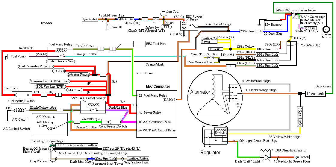
See the following website for some help from Tmoss (diagram designer) &
Stang&2Birds (website host)

http://www.veryuseful.com/mustang/tech/engine/images/IgnitionSwitchWiring.gif

http://www.veryuseful.com/mustang/tech/engine/images/fuel-alt-links-ign-ac.gif

http://www.veryuseful.com/mustang/tech/engine/images/88-91eecPinout.gif

Diagram courtesy of Tmoss & Stang&2birds

fuel-alt-links-ign-ac.gif


Now that you have the theory of how it works, it’s time to go digging.

Look for 12 volts at the Orange/Lt. Blue wire (power source for fuel pump relay).
No voltage or low voltage, bad fuse link, bad wiring, bad ignition switch or ignition
switch wiring or connections. There is a mystery connector somewhere under the
driver’s side kick panel, between the fuel pump relay and the fuse link.

Turn on the key and jumper the fuel pump test connector to ground as previously
described. Look for 12 volts at the Light Pink/Black wire (relay controlled power
for the fuel pump). No voltage there means that the relay has failed, or there is a
broken wire in the relay control circuit.

Check the Red/black wire, it should have 12 volts. No 12 volts there, either the
inertia switch is open or has no power to it. Check both sides of the inertia
switch: there should be power on the Red wire and Red/Black wire. Power on the
Red wire and not on the Red/Black wire means the inertia switch is open.

The Tan/Lt Green wire provides a ground path for the relay power. With the test
connector jumpered to ground, there should be less than .75 volts. Use a test
lamp with one side connected to battery power and the other side to the
Tan/Lt Green wire. The test light should glow brightly. No glow and you have a
broken wire or bad connection between the test connector and the relay. To test
the wiring from the computer, remove the passenger side kick panel and
disconnect the computer connector. It has a 10 MM bolt that holds it in place.
With the test lamp connected to power, jumper pin 22 to ground and the test
lamp should glow. No glow and the wiring between the computer and the fuel
pump relay is bad.

If all of the checks have worked OK to this point, then the computer is bad. The
computers are very reliable and not prone to failure unless there has been
significant electrical trauma to the car. Things like lightning strikes and putting
the battery in backwards or connecting jumper cables backwards are about the
only thing that kills the computer.
 
HISSIN50 said:
You appear to have an issue on the control side of the relay. I'd recheck for 12 volts at the positive relay coil (I dont have a wiring diagram for an 83). And make sure your control ground (what you grounded at the test connector) ohms out well (it should - it looks like a 12 volt issue).

Jrichker's list might have specs going back as far as '83. I'd check his list anyhow if you havent.

Good luck.


It's an 83 w/ all 89 specs....Just to clarify Hissin...Forgot to mention that. So were basically dealing w/ an 89 gt. I grounded the voltometer at the neg. side of the battery to insure I indeed I had a good ground.
 
Jrichker: These are the results I got from the at the fp relay w/ the fp test connector jumpered

Orange / Lt Blue : 12v
Pink / Black : 6.9 mv
Red : 3.7v
Dk Green / Yellow: 7.3 Mv

The last three reading are supposed to be 12v and mine are much much lower? :shrug: And the orange/ lt blue wire that was supposed to have no more than. .75v has 12v? Not sure what any of this means....
 
ram360 said:
Jrichker: These are the results I got from the at the fp relay w/ the fp test connector jumpered

Orange / Lt Blue : 12v
Pink / Black : 6.9 mv
Red : 3.7v
Dk Green / Yellow: 7.3 Mv

The last three reading are supposed to be 12v and mine are much much lower? :shrug: And the orange/ lt blue wire that was supposed to have no more than. .75v has 12v? Not sure what any of this means....
I wont speak for JR, but in case you're workin on this tonight and JR went to bed..............

When the FP is working (i.e. the car is running), 3 wires are hot and one is ground. In JR's diagram, the tan/lt grn wire is the ground from the computer that energizes the FP relay (it is the only ground wire at the FP relay). I will let you infer which wire that is on your relay since you're colors are a hair off from the above-diagram.

It still looks like the EEC relay power is not reaching the FP relay. Inertia switches are known to short or occasionally become resistive.

Random thoughts. Good luck.
 
HISSIN50 said:
I wont speak for JR, but in case you're workin on this tonight and JR went to bed..............

When the FP is working (i.e. the car is running), 3 wires are hot and one is ground. In JR's diagram, the tan/lt grn wire is the ground from the computer that energizes the FP relay (it is the only ground wire at the FP relay). I will let you infer which wire that is on your relay since you're colors are a hair off from the above-diagram.

It still looks like the EEC relay power is not reaching the FP relay. Inertia switches are known to short or occasionally become resistive.

Random thoughts. Good luck.

thanks hissin. I'll check the power on both sides of the inertia switch when I get home from work tonight. The tan/lt green wire I have labeled as dk green/yellow was kinda dark when I was working on it so I had a hard time telling what color it was. At any rate If that's my ground I have 7.3 Mv at that wire?
 
ram360 said:
thanks hissin. I'll check the power on both sides of the inertia switch when I get home from work tonight. The tan/lt green wire I have labeled as dk green/yellow was kinda dark when I was working on it so I had a hard time telling what color it was. At any rate If that's my ground I have 12v at that wire?
Actually, I think you said you had some trace voltage at that wire (7.3 mV). If this was tested after the prime-out or without the self-test connector for the fuel pump grounded (as Jrichker depicted above), the wire might float (Joe can tell you about that stuff).

If you dont have ground at that wire from the puter (remember to switch the setting on your meter), ground the self test FP wire and recheck it. That should definately achieve a decent ground reading (a few Ohms) if you didnt have that before. If that still doesnt work, check for a wiring issue.

Good luck bud.
 
HISSIN50 said:
Actually, I think you said you had some trace voltage at that wire (7.3 mV). If this was tested after the prime-out or without the self-test connector for the fuel pump grounded (as Jrichker depicted above), the wire might float (Joe can tell you about that stuff).

If you dont have ground at that wire from the puter (remember to switch the setting on your meter), ground the self test FP wire and recheck it. That should definately achieve a decent ground reading (a few Ohms) if you didnt have that before. If that still doesnt work, check for a wiring issue.

Good luck bud.

Your right, I did have 7.3mv at that wire...I"m getting myself confused. Sorry bout' that. I did have the self test connector grounded w/ all the readings. I'll check it again. What setting should I change the meter to? I'm basically only understand volts and mv's...anything other than that I've never delt with. I'm very unfamiliar w/ the other settings on the voltometer. Sorry for all the ? but this wiring stuff drives me crazy :bang:
 
I guess I'll check both sides of the 20g blue wire coming from the starter solenoid and make sure the fusable link is still intact. That should be the source of my fuel pump power? If I'm getting 12v there then I'm lost

I can rule out the inertia switch and fp relay as the problems. What does that leave me with? Bad connection somewhere, cut wire? I mean I'm getting power but very very little..
 
The 20gauge link provides power to the KAM and EEC relay.

The FP gets feed-power from an 18 gauge link.

I agree - check that EEC relay feed (that you planned to check). Then head to the EEC relay if needed.

You can also check other systems that are fed by the EEC relay (common terminal at the WOT relay, MAF if applicable, etc). IF those are good, chances are it's a wiring issue between the EEC relay and the inertia switch.

I'd also re-read Joe's diagnostic post above. Now that you've been testing things, what he says might make more sense (for instance, I just saw that he mentions the ground from the puter can float at 750 mA).

Oh, for ground testing, set your meter to Ohms (the upside down lookin U thingie). Put it on the 200 scale (that's the lowest scale I have on my meter, for instance) and check things. A quality ground will be under 5 ohms in many circuits, and should be closer to zero for many computer controlled circuits).

Good luck.
 
Checked the blue 20g from the starter solenoid...before the fueable link 12v after was 3.7v.... Apparently this was the reason for the low readings. When I replace the fuseable link and get 12v running through everything again...will this kick my fuel pump on Hissin? Can I use a blade style fuse w/ holder inline instead of the fuseable link cable or should I stick w/ that... Not really a fan of the fuseable links since I can't tell when they are blown or damaged? Apparently this one is broken enough to allow only 3.7v thru apparently from being handled when I was putting in the solenoid.
 
That should get your power to and through the inertia switch again. And with that having 12 volts and the tan/lt grn providing ground, the relay should energize and supply pink/blk with juice for the pumpito.

Personally, I'd replace it with a link for now. Links are nice in that they are resistant to spikes. And honestly, I'm not sure what size fuse you'd want to use (definately a question for JRichker!). A link is a few bucks and easy enough to replace at your leisure once you know what size fuse or circuit breaker to use.

I'd solder the new link in, if you can.

Good luck.
 
HISSIN50 said:
That should get your power to and through the inertia switch again. And with that having 12 volts and the tan/lt grn providing ground, the relay should energize and supply pink/blk with juice for the pumpito.

Personally, I'd replace it with a link for now. Links are nice in that they are resistant to spikes. And honestly, I'm not sure what size fuse you'd want to use (definately a question for JRichker!). A link is a few bucks and easy enough to replace at your leisure once you know what size fuse or circuit breaker to use.

I'd solder the new link in, if you can.

Good luck.

ok I'll use another link...Just was thinking maybe a blade fuse was better from a visual standpoint for diagnosing a problem if it ever happened again....but I didn't think about voltage spikes etc... I'll buy one tomorrow and see what happens....Hopefully good news. :flag:
 
For some reason nobody sells a 20g fusable link...went to 3 or 4 places and the best I could do was a 16g fuseable link....Hopefully I'm not harming anything by doing this but that's as close as I can get. Needless to say, I change the fueable link and the fp kicked right on. Thanks Hissin.