Fuel Pump Troubleshooting for 87-90 Mustangs
Revised 08-Aug-2011 to update check for no power at the inetia switch.
Clue – listen for the fuel pump to prime when you first turn the ignition switch on.
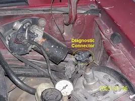
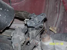
It should run for 5-20 seconds and shut off. To trick the fuel pump into running,
find the ECC test connector and jump the connector in the upper RH corner to
ground.
If the fuse links are OK, you will have power to the pump. Check fuel pressure –
remove the cap from the Schrader valve behind the alternator and depress the
core. Fuel should squirt out, catch it in a rag. A tire pressure gauge can also be
used if you have one - look for 37-40 PSI. Beware of fire hazard when you do this.
No fuel pressure, possible failed items in order of their probability:
A.) Tripped inertia switch – press reset button on the inertia switch. The hatch
cars hide it under the plastic trim covering the driver's side taillight. Use the
voltmeter or test light to make sure you have power to both sides of the switch
B.) Fuel pump power relay – located under the driver’s seat in most Mustangs built
before 92.
C.) Clogged fuel filter
D.) Failed fuel pump
E.) Blown fuse link in wiring harness.
F.) Fuel pressure regulator failed. Remove vacuum line from regulator and inspect
for fuel escaping while pump is running.
The electrical circuit for the fuel pump has two paths, a control path and a power
path.
The control path consists of the inertia switch, the computer, and the fuel pump
relay coil. It turns the fuel pump relay on or off under computer control. The
switched power (red wire) from the ECC relay goes to the inertia switch
(red/black wire) then from the inertia switch to the relay coil and then from the
relay coil to the computer (tan/ Lt green wire). The computer provides the ground
path to complete the circuit. This ground causes the relay coil to energize and
close the contacts for the power path. Keep in mind that you can have voltage
to all the right places, but the computer must provide a ground. If there is no
ground, the relay will not close the power contacts.
The power path picks up from a fuse link near the starter relay. Fuse links are like
fuses, except they are pieces of wire and are made right into the wiring harness.
The feed wire from the fuse link (orange/ light blue wire) goes to the fuel pump
relay contacts. When the contacts close because the relay energizes, the power
flows through the contacts to the fuel pump (light pink/black wire). Notice that
pin 19 on the computer is the monitor to make sure the pump has power.
The fuel pump has a black wire that supplies the ground to complete the circuit.
Remember that the computer does not source any power to actuators, relays
or injectors, but provides the ground necessary to complete the circuit. That
means one side of the circuit will always be hot, and the other side will go to
ground or below 1 volt as the computer switches on that circuit.
Now that you have the theory of how it works, it’s time to go digging.
All voltage reading are made with one voltmeter lead connected to the metal
car body unless otherwise specified
Check for 12 volts at the red wire on the inertia switch. No 12 volts at the inertia switch,
the ignition switch is turned off or faulty or there is no power to the ECC (computer )
power relay. To be sure look for good 12 volts on the red wire on any fuel injector:
good 12 volts mean the ECC relay is working. No 12 volts and the ECC wiring is at
fault.
Look for 12 volts on the red/green wire on the ignition coil: no 12 volts and the
ignition switch is faulty, or the fuse link in the ignition power wire has blown. No 12 volts
here and the ECC relay won’t close and provide power to the inertia switch.
Check the Red/black wire on the inertia switch, it should have 12 volts. No 12 volts there,
either the inertia switch is open or has no power to it. Check both sides of the inertia
switch: there should be power on the Red wire and Red/Black wire. Power on the
Red wire and not on the Red/Black wire means the inertia switch is open. Push the button
on the side of it to reset it, and then recheck. Good 12 volts on one side and not on the other
means the inertia switch has failed
Look for 12 volts at the Orange/Lt. Blue wire (power source for fuel pump relay).
No voltage or low voltage, bad fuse link, bad wiring, bad ignition switch or ignition
switch wiring or connections. There is a mystery connector somewhere under the
driver’s side kick panel, between the fuel pump relay and the fuse link.
Turn on the key and jumper the fuel pump test connector to ground as previously
described. Look for 12 volts at the Light Pink/Black wire (relay controlled power
for the fuel pump). No voltage there means that the relay has failed, or there is a
broken wire in the relay control circuit.
Pump wiring: Anytime the ignition switch is in the Run position and the test
point is jumpered to ground, there should be at least 12 volts present on the
black/pink wire. With power off, check the pump ground: you should see less
than 1 ohm between the black wire and chassis ground.
The yellow wire is the fuel tank sender to the fuel quantity gage. The two black wires are grounds.
One ground is for the fuel tank sender and the other is the fuel pump. The ground for the fuel pump
may be larger gauge wire that the fuel tank sender ground wire.
Make sure that the power is off the circuit before making any resistance checks. If the circuit
is powered up, your resistance measurements will be inaccurate.
You should see less than 1 Ohm between the black wire(s) and ground. To get some idea of what
a good reading is, short the two meter leads together and observe the reading. It should only be
slightly higher when you measure the black wire to ground resistance.
The Tan/Lt Green wire provides a ground path for the relay power. With the test
connector jumpered to ground, there should be less than .75 volts. Use a test
lamp with one side connected to battery power and the other side to the
Tan/Lt Green wire. The test light should glow brightly. No glow and you have a
broken wire or bad connection between the test connector and the relay. To test
the wiring from the computer, remove the passenger side kick panel and
disconnect the computer connector. It has a 10 MM bolt that holds it in place.
With the test lamp connected to power, jumper pin 22 to ground and the test
lamp should glow. No glow and the wiring between the computer and the fuel
pump relay is bad.
Computer: If you got this far and everything else checked out good, the computer is suspect.
Remove the test jumper from the ECC test connector located under the hood.
Probe computer pin 22 with a safety pin and ground it to chassis. Make sure the computer
and everything else is connected. Turn the ignition switch to the Run position and observe
the fuel pressure. The pump should run at full pressure.
If it doesn't, the wiring between pin 22 on the computer and the fuel pump relay is bad.
If it does run at full pressure, the computer may have failed.
Keep in mind that the computer only runs the fuel pump for about 2-3 seconds when you turn
the key to the Run position. This can sometimes fool you into thinking the computer has died.
Connect one lead of the test light to power and the other lead to computer pin 22 with a safety pin.
With the ignition switch Off, jumper the computer into self test mode like you are going to dump
the codes. Turn the ignition switch to the Run position. The light will flicker when the computer
does the self test routine. A flickering light is a good computer. No flickering light is a bad computer.
Remove the test jumper from the ECC test connector located under the hood.
Fuel pump runs continuously: The fuel pump relay contacts are stuck together or the Tan/Lt Green wire
has shorted to ground. Remove the fuel pump relay from its socket. Then disconnect the computer and use
an ohmmeter to check out the resistance between the Tan/Lt Green wire and ground. You should see
more than 10 K Ohms (10,000 ohms) or an infinite open circuit. Be sure that the test connector isn’t
jumpered to ground.
If the wiring checks out good, then the computer is the likely culprit.
Prior to replacing the computer, check the computer power ground. The computer has its own
dedicated power ground that comes off the ground pigtail on the battery ground wire. Due to
it's proximity to the battery, it may become corroded by acid fumes from the battery. It is a
black cylinder about 2 1/2" long by 1" diameter with a black/lt green wire. You'll find it up
next to the starter solenoid where the wire goes into the wiring harness
If all of the checks have worked OK to this point, then the computer is bad. The
computers are very reliable and not prone to failure unless there has been
significant electrical trauma to the car. Things like lightning strikes and putting
the battery in backwards or connecting jumper cables backwards are about the
only thing that kills the computer.
See the following website for some help from Tmoss (diagram designer) &
Stang&2Birds (website host)
http://www.veryuseful.com/mustang/tech/engine/images/IgnitionSwitchWiring.gif
http://www.veryuseful.com/mustang/tech/engine/images/fuel-alt-links-ign-ac.gif
http://www.veryuseful.com/mustang/tech/engine/images/88-91eecPinout.gif