91 Mustang Intermittent Injector Pulse

Toomanymustangs

Active User
May 23, 2017
13
1
3
Hi and thanks for reading. I'm new to this and hoping for a little direction.

I have the classic cranks but not start and have been through many checklists (jriccher) if he is still active. Very helpful.

I have spark off the coul and off plug. 38 pounds of fuel pressure .. Pumps comes on for a few seconds and stops at 38 according to the pressure tester. I have 12 volts on the red wire of one injector. Haven't tested them all. TPS has a 4.95v reference, ohms at 1.2 and with key on tps is at .94.

My eec relay is good and has all of the right specs per the dvom.

My problem I THINK is this... Or my symptom rather. With a noid light on the injector I've check that has 12v on the red wire, when I spin the car over it DOES pulse.. But only intermittently. It will pulse for a few seconds and then stay lit for a few seconds and then pulse again. Back and forth like that. As it is doing this, I can hear the fuel pump relay under the seat clicking on and off.

I'm thinking next I should pull the intake to access all injectors and check for 12v at all red wires on the injectors and then check the injector pins on the computer.

Does anyone have a thought on that? I've found threads of no pulse, of noid light staying lit and etc, but can't find anything on pulsing and then staying lit back and forth.

Thanks!
 
  • Sponsors (?)


Oh... It's an all stock 91 5.0 H.O. And was running when I parked it in the garage a year ago. It was running good but had developed a miss and smelled rich.

Only mods are a k&n and some headers. It's an automatic.
 
I'm gonna move this to the 5.0 tech threads so you can get some help, one thing I say to nearly everybody that has a problem with a no start condition is to check all your grounds, there are 4 under the hood and one buy the computer in the passenger kick panel, these are very important for computer functions.
 
The intermittent noid light points to a problem with the PIP sensor in the distributor.

Dump the codes and see if you get

Dump codes sticky.
Look at the top of the 5.0 Tech forum where the sticky threads are posted. One of them is how to dump the computer codes. http://www.stangnet.com/mustang-for...codes-from-eec4-in-86-95-5-0-mustangs.889006/ I highly suggest that you read it and follow the instructions to dump the codes.


Code 14 - Ignition pickup (PIP) was erratic – the Hall Effect sensor in the distributor is failing. Bad sensor, bad wiring, dirty contacts. Factory tach will sometimes read erratically.

Revised 10-Dec-2012 to add PIP diagnostic testing & Wells info

The PIP is a Hall Effect magnetic sensor that triggers the TFI and injectors. There is a shutter wheel alternately covers and uncovers a fixed magnet as it rotates. The change in the magnetic field triggers the sensor. They are often heat sensitive, increasing the failure rate as the temperature increases.

PIP Sensor functionality, testing and replacement:
The PIP is a Hall Effect magnetic sensor that triggers the TFI and injectors. There is a shutter wheel alternately covers and uncovers a fixed magnet as it rotates. The change in the magnetic field triggers the sensor. A failing PIP sensor will often set code 14 in the computer. They are often heat sensitive, increasing the failure rate as the temperature increases.

Some simple checks to do before replacing the PIP sensor or distributor:
You will need a Multimeter or DVM with good batteries: test or replace them before you get started.. You may also need some extra 16-18 gauge wire to extend the length of the meter’s test leads.
Visual check first: look for chaffed or damaged wiring and loose connector pins in the TFI harness connector.
Check the IDM wiring – dark green/yellow wire from the TFI module to pin 4 on the computer. There is a 22K Ohm resistor in the wiring between the TFI and the computer. Use an ohmmeter to measure the wire resistance from the TFI to the computer. You should see 22,000 ohms +/- 10%.
Check the PIP wiring - dark blue from the TFI module to pin 56 on the computer. Use an ohmmeter to measure the wire resistance from the TFI to the computer. You should see 0.2-1.5 ohms.
Check the SPOUT wiring – yellow/lt green from the TFI module to pin 36 on the computer. Use an ohmmeter to measure the wire resistance from the TFI to the computer. You should see 0.2-1.5 ohms.
Check the black/orange wire from the TFI module to pin 16 on the computer. Use an ohmmeter to measure the wire resistance from the TFI to the computer. You should see 0.2-1.5 ohms.
Check the red/green wire; it should have a steady 12-13 volts with the ignition switch on and the engine not running.
Check the red/blue wire; it should have a steady 12-13 volts with the ignition switch in Start and the engine not running. Watch out for the fan blades when you do this test, since the engine will be cranking.
If you do not find any chaffed or broken wires, high resistance connections or loose pins in the wiring harness, replace the PIP sensor or the distributor.

The PIP sensor is mounted in the bottom of the distributor under the shutter wheel. In stock Ford distributors, you have to press the gear off the distributor shaft to get access to it to replace it. Most guys just end up replacing the distributor with a reman unit for about $75 exchange

PIP problems & diagnostic info
Spark with the SPOUT out, but not with the SPOUT in suggests a PIP problem. The PIP signal level needs to be above 6.5 volts to trigger the computer, but only needs to be 5.75 volts to trigger the TFI module. Hence with a weak PIP signal, and the SPOUT out, you could get spark but no injector pulse. You will need an oscilloscope or graphing DVM to measure the output voltage since it is not a straight DC voltage.

See http://www.wellsmfgcorp.com/pdf/counterp_v8_i2_2004.pdf and http://www.wellsmfgcorp.com/pdf/counterp_v8_i3_2004.pdf for verification of this little detail from Wells, a manufacturer of TFI modules and ignition system products.
 
Hey hey J! To the rescue! I was just about to post another thing I thought of when I saw you had replied ...

The car won't go into self test mode to dump codes. I read that you should get some initial flashes (quick flashes).... Well this car doesn't do that. When you jump the tester to dump codes and turn the key on the check engine light comes on and just stays lit solid.

Should I test the ohms between the red/gray wire and negative batt cable and look for 1.5 or less? Then check the Ecc?


Computer will not go into diagnostic mode on 91-95 model 5.0 Mustangs

Revised 7-June-2014 to change resistance figures to wiring checks

How it is supposed to work:
The grey/red wire (pin 46) is signal ground for the computer. It provides a dedicated ground for the EGR, Baro, ACT, ECT, & TPS sensors as well as the ground to put the computer into self-test mode. As long as you are successful dumping the codes by using the gray/red wire on the diagnostic connector for the ground when dumping, the computer’s internal ground on pin 46 is good.

If this ground is bad, none of the sensors mentioned will work properly. That will severely affect the car's performance. You will have hard starting, low power and drivability problems. Since it is a dedicated ground, it passes through the computer on its way to the computer main power ground that terminates at the battery pigtail ground. It should read less than 1 ohm when measured from anyplace on the engine harness with the battery pigtail ground as the other reference point for the ohmmeter probe.

What sometimes happens is that the test connector grey/red wire gets jumpered to power which either burns up the wiring or burns the trace off the pc board inside the computer. That trace connects pins 46 to pins 40 & 60.

The STI (Self Test Input ) is jumpered to ground to put the computer into test mode. Jumpering it to power can produce unknown results, including damage to the computer. The ohm test simply verifies that there are no breaks in the wiring between the test connector and the computer input.

How to test the wiring :
With the power off, measure the resistance between the computer test ground (grey/red wire) on the self- test connector and battery ground. You should see less than 1 ohm.

attachment.php


If that check fails, remove the passenger side kick panel and disconnect the computer connector. There is a 10 MM bolt that holds it in place. Measure the resistance between the grey/red wire and pin 46 on the computer wiring connector: it should be less than 1 ohm. More than 1 ohm is a wiring problem. If it reads 1 ohm or less, then the computer is suspect. On the computer, measure the resistance between pin 46 and pins 40 & 60: it should be less than 1 ohm. More than that and the computer’s internal ground has failed, and the computer needs to be repaired or replaced.

See http://www.stangnet.com/mustang-forums/749974-computer-issue.html#post7490537 for Joel5.0’s fix for the computer internal signal ground.

If the first ground check was good, there are other wires to check. Measure the resistance between the STI computer self-test connector (red/white wire) and pin 48 on the computer main connector: it should be less than 1.5 ohms. More than 1 ohms is a wiring problem

The following is a view from the computer side of the computer wiring connector: it is for an A9L, A9P computer.
eec-iv-computer-connector-for-5-0-mustang-gif.88243


a9x-series-computer-connector-wire-side-view-gif.71316


Diagram courtesy of Tmoss & Stang&2birds

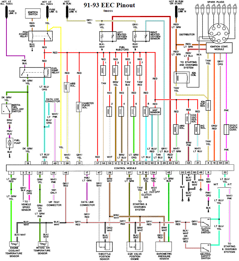
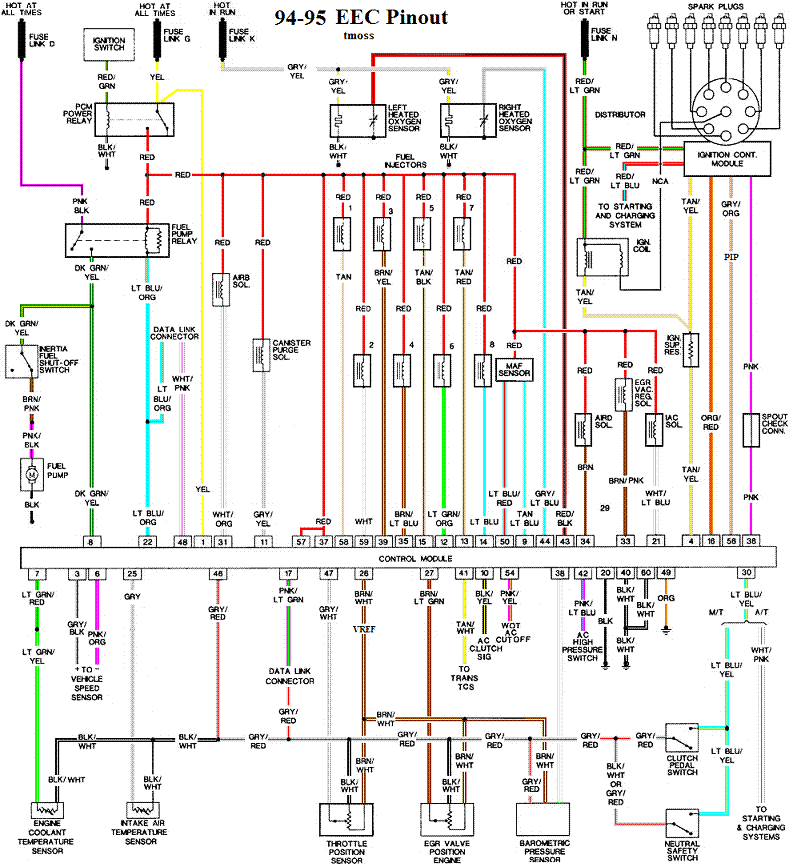
Check out the diagram and notice all the places the grey/red wire goes. Almost every sensor on the engine except the MAF is connected to it.

91-93 5.0 Mustangs
91-93_5.0_EEC_Wiring_Diagram.gif


Complete computer, actuator & sensor wiring diagram for 94-95 Mass Air Mustangs
94-95_5.0_EEC_Wiring_Diagram.gif


See the graphic for the 10 pin connector circuit layout.
salt-pepper-10-pin-connectors-65-jpg.68512


See the following website for some help from Tmoss (diagram designer) & Stang&2Birds
(website host) for help on 88-95 wiring http://www.veryuseful.com/mustang/tech/engine
 
Ok... First test.. Resistance between Grey/red wire on self test connector and battery ground with power off was 0.9 ohms

Second test, resistance between self connector white/red and pin 48 on computer main connector was .5 ohms

I tried that first. Haven't tried the ohm readings on the tfi module with computer yet.
 
Okay so... I tried to do the readings between my tfi connector and computer connector. The first thing I discovered was that my wires weren't the same color as in the description. I started then with the first wire and pin 4 on the computer connector and could never find one that would register anything close to 22k resistance. I thought maybe someone had chopped the harness and spliced in some other year model.. then I remembered something about a push start version vs a computer controlled dwell tfi?

I have no idea what that is. But mine is a gray distributor mounted tfi and I can't find any wire on it that produces anything close to what the IDM result should be.

Thoughts?
 

Attachments

  • image.jpeg
    image.jpeg
    328.5 KB · Views: 276
  • image.jpeg
    image.jpeg
    476.1 KB · Views: 250
Ok I found the IDM wire (for some reason mine is tan and yellow) and that wire has no resistance I can measure from tfi connector to pin 4. I don't know where the 22k ohm resistor would be located but I can't find it anywhere in the wire.

Could this be part of the issue along with the pip?
 
Ok here's an update... I went back to check the tfi resistance against the computer pins again and the start wires. As it turns out, the extension wire I was using to run the test had a break in it.

Retested with good test wire and got results that meet specifications on every single test. That's good news. I will order a distributor in the morning and hopefully that will fix it. Thanks so much for your help.

I do have one more question.. Am I right in thinking that the intermittent injector pulse I'm having (failing pip) could cause the fuel pump relay to click on and off?

The computer uses the PIP pulse to keep the fuel pump turned on.

A repetitive string of pulses above a certain minimum value keeps the computer controlled fuel pump relay ground turned on. That is what helps to keep the engine from flooding with fuel when the ignition is left in the On position while the engine isn't running.
 
  • Like
Reactions: 1 user
I have a new motorcraft pip on the way. I have two motorcraft distributors now, one is the original and one is a reman I bought a couple of years back. As I understand it most companies simply test the pip and if it passes they don't replace it when they do a reman. This way I will hopefully know I have a good one if its new. I'll let you know if that does the trick.
 
Well it's fixed. Wound up being the ECM. Got a Cardone 78-5611 (reman motorcraft A9p) from Autozone and it fired right up. I'm gonna put the new pip in when it gets here too just so it has a new one. Gotta put the light on it to check timing too but it's running good.

Thanks for the help. I needed to check all of those wires to be sure and that was a great help.
 
  • Like
Reactions: 1 user
Well it's fixed. Wound up being the ECM. Got a Cardone 78-5611 (reman motorcraft A9p) from Autozone and it fired right up. I'm gonna put the new pip in when it gets here too just so it has a new one. Gotta put the light on it to check timing too but it's running good.

Thanks for the help. I needed to check all of those wires to be sure and that was a great help.
Thank you for your update. I don't see many computer failures, and intermittent problems are difficult to chase over the internet. I am glad to hear that you got it running. Enjoy the summer and your Mustang!
 
So... What's the world record time for smoking a computer? Lol

Not funny but it will be when this is over. Here's what happened .. Tell me if you think this would smoke it.

I plugged in the new eec. Ran perfect. I switched the car off unhooked negative battery cable and went to put the eec and kick panel back in place and one of the connectors was REALLY in the way. I tried to unplug it and it just was too much trouble however I did get it about halfway unplugged.

Well I forgot about it. Had some pizza and came back out. Managed to get the computer in place and then tried to start to car again after reconnecting battery. I didn't start and I heard a pop. Then I remembered the connector. So I pushed the two sockets of the connector back together (all the way) and after that had no spark from the coil. I replaced the coil.

I have spark at the coil, spark at the plugs, injectors are pulsing perfect per the noid light and 38 pounds of fuel pressure. Tps voltage checks right. I replaced the tfi too. Still nothing. Rechecked tfi wires to computer pins and also verified correct readings for pins 1,40,60,37 and 57.

I'll post a picture of the connector and if you don't mind tell me if you think that could have smoked the new computer.

Then we can all laugh. And I'll laugh with you. What an idiot lol
 

Attachments

  • image.jpeg
    image.jpeg
    458.7 KB · Views: 201