MORE voltage problems....3g set up

jmd2914

Founding Member
Sep 6, 2002
937
0
0
Napa, California
I'm still having voltage problems with my mustang. i have a 3g on the car. voltage is fine when the car is warm and at idle, almost a bit on the low side, but whent here is load put on the car or the car is cold the voltage is way up at the top of the guage and about half the time the amp light is blinking. alternator is new ( bought it 2 days ago cuz my other one died) what can cause such high voltage?? i thought the regulator at first but its a new alt. its getting so bad it blew out my high beams when i turned them on. ( on a side note if my high beams dont work but my low beams do, replacing the bulbs will fix this right?)

thanks in advance for any help, im at my wits end with this one

J
 
  • Sponsors (?)


yep, I remember swapping my alternator 4 times in one day, because if it wasn't the bearings, or rectifier, it was the stupid Diodes in the Regulator. It its going bad, your getting too many volts to your battery, and it will ruin that in the mean time.

Just because it's new doesn't mean it can't be bad. I now have all mine tested before leaving the store. It's easy.
 
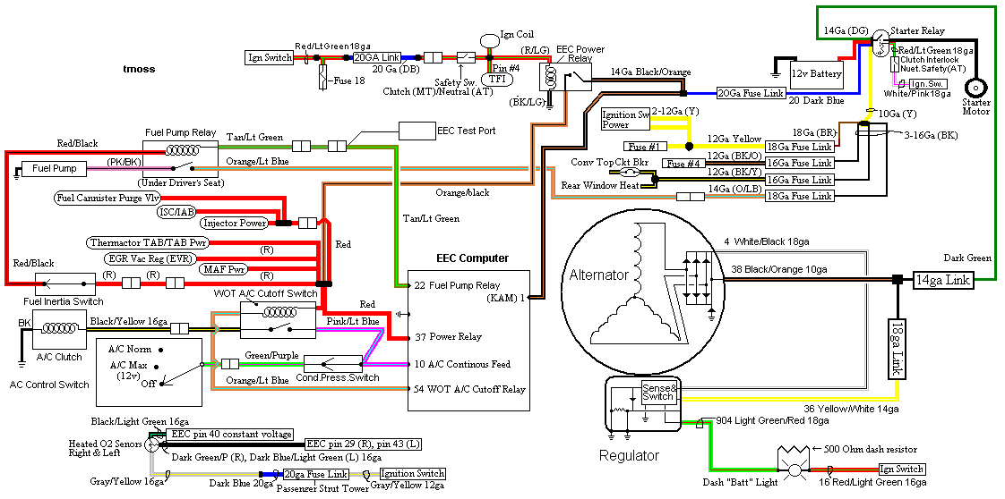
If the sense wire (yellow/white wire that connects to the D shaped alternator plug) has a bad connection, it could cause problems.

attachment.php


Disconnect the negative battery terminal and measure the resistance of the yellow/white wire wire from the tab to the starter solenoid. You should see less than 1 Ohm.

Diagrams courtesy of Tmoss & Stang&2birds
fuel-alt-links-ign-ac.gif


See the following website for some help from Tmoss (diagram designer) & Stang&2Birds
(website host) for help on 86-95 5.0 Mustang wiring Mustang FAQ - Engine Information Everyone should bookmark this site.


Ignition switch wiring
http://www.veryuseful.com/mustang/tech/engine/images/IgnitionSwitchWiring.gif

Fuel, alternator, A/C and ignition wiring
http://www.veryuseful.com/mustang/tech/engine/images/fuel-alt-links-ign-ac.gif

Complete computer, actuator & sensor wiring diagram for 88-91 5.0 Mass Air Mustangs
http://www.veryuseful.com/mustang/tech/engine/images/88-91_5.0_EEC_Wiring_Diagram.gif

Complete computer, actuator & sensor wiring diagram for 91-93 5.0 Mass Air Mustangs
http://www.veryuseful.com/mustang/tech/engine/images/91-93_5.0_EEC_Wiring_Diagram.gif

Complete computer, actuator & sensor wiring diagram for 94-95 5.0 Mass Air Mustangs
http://www.veryuseful.com/mustang/tech/engine/images/94-95_5.0_EEC_Wiring_Diagram.gif

Vacuum diagram 89-93 Mustangs
http://www.veryuseful.com/mustang/tech/engine/images/mustangFoxFordVacuumDiagram.jpg

HVAC vacuum diagram
http://www.veryuseful.com/mustang/tech/engine/images/Mustang_AC_heat_vacuum_controls.gif

TFI module differences & pinout
http://www.veryuseful.com/mustang/tech/engine/images/TFI_5.0_comparison.gif

Fuse box layout
http://www.veryuseful.com/mustang/tech/engine/images/MustangFuseBox.gif
 
If the sense wire is open, the battery light illuminates.
If the wire is compromised (what Joe is talking about), it can cause overcharging. Simply check voltage at that wire (at the regulator. It's labeled A) vs your battery vs your charge stud on the alt. All should be within 1/2V (I don't like to see more than 0.2V difference)
 
so just to make sure i have this right, with everything still connected, check the voltage at the wire, the lug on the alt and the battery? and everything should be about the same? if that wire turns out to be bad, whats the best way to go about fixing it? just take the entire thing out of the wiring harness and replace it?
 
Everything is connected and the car is idling (you can do it with the car off if you need, like if you're afraid to blowing lights and such).

The sense wire should be fine - it'd be a freak thing if it was compromised but not totally broken (to overcharge, there'd have to be a lot of resistance in the circuit, so the alternator thought there was a large voltage drop in the charge cable and upped the output). I suppose a partially burned fusible link on that wire could do it but I haven't seen that happen.

There's a bigger chance that the charge cable is actually dropping a lot of voltage and the regulator and sense circuit are doing what they're designed to do.

The charge cable should drop less than .5V (though anything over .2 is unacceptable to me). To test that, set your meter to 20 DC V. Then just put one meter lead on the charge stud and one on the solenoid. The voltage reading on your meter is the drop.
 
just to cover it even though this is a stupid question, the charge cable is the 4g wire connected to the lug on the back of the alt right? also im running ( if memory serves) a 150amp circuit breaker ( in place of the 150amp fuse) so the charge cable comes out of the alt through the circuit breaker then over to the solinoid. could that breaker have something to do with it? ( im gonna test all that has been talked about when i get home but im stuck at work all night so i figured id just ask as many questions as i can)
 
just to cover it even though this is a stupid question, the charge cable is the 4g wire connected to the lug on the back of the alt right? also im running ( if memory serves) a 150amp circuit breaker ( in place of the 150amp fuse) so the charge cable comes out of the alt through the circuit breaker then over to the solinoid. could that breaker have something to do with it? ( im gonna test all that has been talked about when i get home but im stuck at work all night so i figured id just ask as many questions as i can)

You'll be testing that charge cable (the 4 AWG cable) and the circuit breaker (indirectly) when doing the drop test.

If you're curious, you can do the drop test on the circuit breaker itself (put one lead on each lug and see what your meter shows. It should be almost zero V). You can do this with the car running or off, but it's more useful to test when the car is running (and there's a load running through the cable).
 
i checked the voltage drop from the alt lug to the starter relay and if i did it right i had about
.8V

That's unacceptable IMHO. Did you do the same test on your circuit breaker to see if that's where the voltage is dropping? In any case, start testing (using one lead on the alternator's charge post and the other lead on the location of your choice) to see where the voltage drops off.
 
i had my dad double check my work, when we checked the voltage drops again. things seemed to check out alright. however i noticed my posetive cable on the battery was loose. ( the two top screws that hold the cable to the lug.) i tightened them down just to make sure. would that cause overcharging inadvertantly?
 
A bad battery connection can definitely cause an issue (I've seen it cause quickly fluctuating voltage output).

You have the battery connector where the raw wire sandwiches under a flat plate (with two bolts that hold the plate secure)? Those can be problematic in general.
 
yeah, when i bought new battery cables it came with one like that for the positive side and a regular one for a the negative side. what kind should i buy? on a side note i tightened those bolts down and the problem seems to be fixed
 
Some help with wiring and grounds...

The secondary power ground is between the back of the
intake manifold and the driver's side firewall. It is often missing or
loose. It supplies ground for the alternator, A/C compressor
clutch and other electrical accessories such as the gauges.
Any car that has a 3G or high output current alternator needs
a 4 gauge ground wire running from the block to the chassis
ground where the battery pigtail ground connects.

The 3G has a 130 amp capacity, so you wire the power side
with 4 gauge wire. It stands to reason that the ground side
handles just a much current, so it needs to be 4 gauge too.

The picture shows the common ground point for the battery & extra 3G
alternator ground wire as described above in paragraph 2. A screwdriver
points to the bolt that is the common ground point.
The battery common ground is a 10 gauge pigtail with the computer ground
attached to it.

The clamp on with 2 bolts battery terminal ends are a know problem causer.
Anyplace you see green on a copper wire is corrosion. Corrosion gets in the
clamped joint and works its way up the wire under the insulation.
Avoid them like the plague...

Picture courtesy timewarped1972
ground.jpg


Correct negative battery ground cable.
56567d1230679358-positive-negative-battery-cable-questions-86-93-mustang-oem-style-ground-cable.gif