Cranks OK, but No Start. No Injector Pulse...

J,
Can you explain this sentence from your other post? "Since I don't have any electrical contact cleaner handy, so it's time to take a small screwdriver and close up #2 pin and the pins on each side of it." I had this one apart and it we "ok", and cleaned it with electrical cleaner. specifically the phase "close up #2 pin". Do you mean tighten the female side to make a better connection?

I cannot get the car to respond to the KOEO test. If I take the battery power away will it dump the codes?

Rob
 
  • Sponsors (?)


U
J,
Can you explain this sentence from your other post? "Since I don't have any electrical contact cleaner handy, so it's time to take a small screwdriver and close up #2 pin and the pins on each side of it." I had this one apart and it we "ok", and cleaned it with electrical cleaner. specifically the phase "close up #2 pin". Do you mean tighten the female side to make a better connection?

I cannot get the car to respond to the KOEO test. If I take the battery power away will it dump the codes?

Rob
Use a small screwdriver to close up the opening in the female pins. Be gentle but firm and you can close the female pin opening so that it fits more snugly around the male pin. Push the small screwdriver in alongside the female pin and pry towards the center of the pin.


Fix that first and here is some testing to do to find out why you can't get the codes to dump...

Computer will not go into diagnostic mode on 91-95 model 5.0 Mustangs

Revised 7-June-2014 to change resistance figures to wiring checks

How it is supposed to work:
The grey/red wire (pin 46) is signal ground for the computer. It provides a dedicated ground for the EGR, Baro, ACT, ECT, & TPS sensors as well as the ground to put the computer into self-test mode. If this ground is bad, none of the sensors mentioned will work properly. That will severely affect the car's performance. You will have hard starting, low power and drivability problems. Since it is a dedicated ground, it passes through the computer on its way to the computer main power ground that terminates at the battery pigtail ground. It should read less than 1 ohm when measured from anyplace on the engine harness with the battery pigtail ground as the other reference point for the ohmmeter probe.

What sometimes happens is that the test connector grey/red wire gets jumpered to power which either burns up the wiring or burns the trace off the pc board inside the computer. That trace connects pins 46 to pins 40 & 60.

The STI (Self Test Input ) is jumpered to ground to put the computer into test mode. Jumpering it to power can produce unknown results, including damage to the computer. The ohm test simply verifies that there are no breaks in the wiring between the test connector and the computer input.

How to test the wiring :
With the power off, measure the resistance between the computer test ground (grey/red wire) on the self- test connector and battery ground. You should see less than 1 ohm.

attachment.php


If that check fails, remove the passenger side kick panel and disconnect the computer connector. There is a 10 MM bolt that holds it in place. Measure the resistance between the grey/red wire and pin 46 on the computer wiring connector: it should be less than 1 ohm. More than 1 ohm is a wiring problem. If it reads 1 ohm or less, then the computer is suspect. On the computer, measure the resistance between pin 46 and pins 40 & 60: it should be less than 1 ohm. More than that and the computer’s internal ground has failed, and the computer needs to be repaired or replaced.

See http://www.stangnet.com/mustang-forums/749974-computer-issue.html#post7490537 for Joel5.0’s fix for the computer internal signal ground.

If the first ground check was good, there are other wires to check. Measure the resistance between the STI computer self-test connector (red/white wire) and pin 48 on the computer main connector: it should be less than 1.5 ohms. More than 1 ohms is a wiring problem

The following is a view from the computer side of the computer wiring connector: it is for an A9L, A9P computer.
eec-iv-computer-connector-for-5-0-mustang-gif.88243.gif


a9x-series-computer-connector-wire-side-view-gif.71316.gif


Diagram courtesy of Tmoss & Stang&2birds

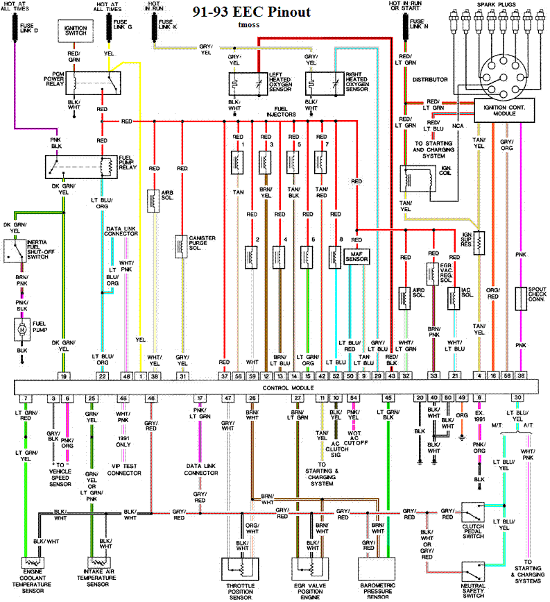
Check out the diagram and notice all the places the grey/red wire goes. Almost every sensor on the engine except the MAF is connected to it.

91-93 5.0 Mustangs
91-93_5.0_EEC_Wiring_Diagram.gif


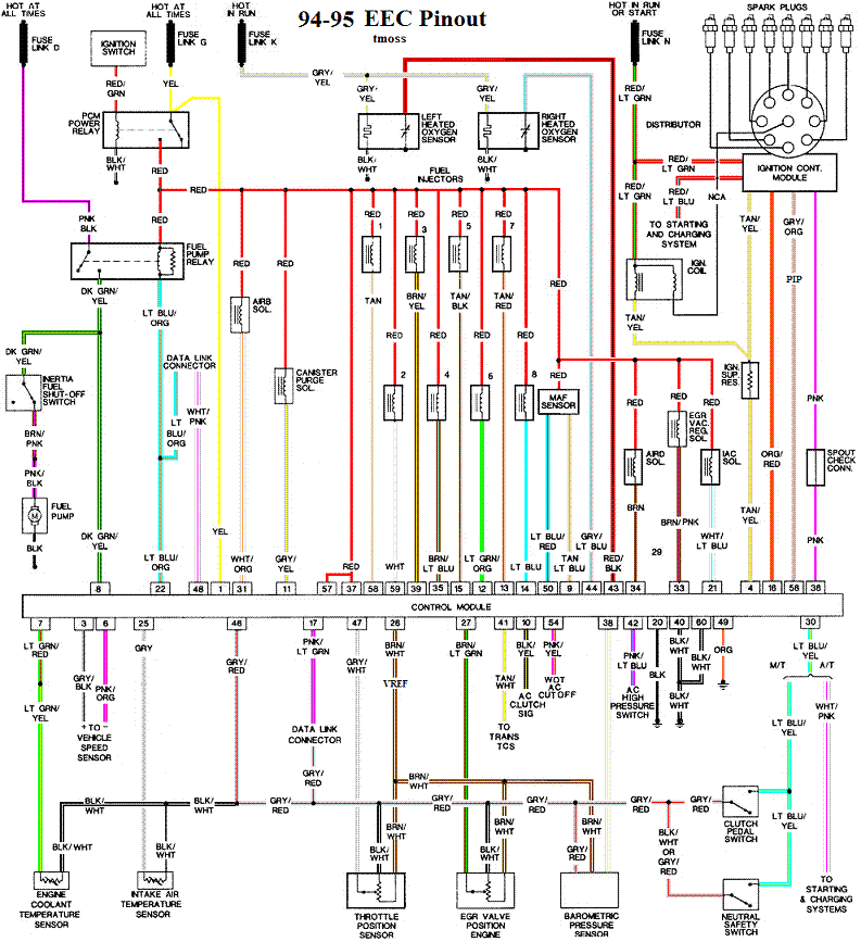
Complete computer, actuator & sensor wiring diagram for 94-95 Mass Air Mustangs
94-95_5.0_EEC_Wiring_Diagram.gif


See the graphic for the 10 pin connector circuit layout.
salt-pepper-10-pin-connectors-65-jpg.68512


See the following website for some help from Tmoss (diagram designer) & Stang&2Birds
(website host) for help on 88-95 wiring http://www.veryuseful.com/mustang/tech/engine
 
U
Use a small screwdriver to close up the opening in the female pins. Be gentle but firm and you can close the female pin opening so that it fits more snugly around the male pin. Push the small screwdriver in alongside the female pin and pry towards the center of the pin.


Fix that first and here is some testing to do to find out why you can't get the codes to dump...

Computer will not go into diagnostic mode on 91-95 model 5.0 Mustangs

Revised 7-June-2014 to change resistance figures to wiring checks

How it is supposed to work:
The grey/red wire (pin 46) is signal ground for the computer. It provides a dedicated ground for the EGR, Baro, ACT, ECT, & TPS sensors as well as the ground to put the computer into self-test mode. If this ground is bad, none of the sensors mentioned will work properly. That will severely affect the car's performance. You will have hard starting, low power and drivability problems. Since it is a dedicated ground, it passes through the computer on its way to the computer main power ground that terminates at the battery pigtail ground. It should read less than 1 ohm when measured from anyplace on the engine harness with the battery pigtail ground as the other reference point for the ohmmeter probe.

What sometimes happens is that the test connector grey/red wire gets jumpered to power which either burns up the wiring or burns the trace off the pc board inside the computer. That trace connects pins 46 to pins 40 & 60.

The STI (Self Test Input ) is jumpered to ground to put the computer into test mode. Jumpering it to power can produce unknown results, including damage to the computer. The ohm test simply verifies that there are no breaks in the wiring between the test connector and the computer input.

How to test the wiring :
With the power off, measure the resistance between the computer test ground (grey/red wire) on the self- test connector and battery ground. You should see less than 1 ohm.

attachment.php?attachmentid=57945&stc=1&d=1240584741.gif


If that check fails, remove the passenger side kick panel and disconnect the computer connector. There is a 10 MM bolt that holds it in place. Measure the resistance between the grey/red wire and pin 46 on the computer wiring connector: it should be less than 1 ohm. More than 1 ohm is a wiring problem. If it reads 1 ohm or less, then the computer is suspect. On the computer, measure the resistance between pin 46 and pins 40 & 60: it should be less than 1 ohm. More than that and the computer’s internal ground has failed, and the computer needs to be repaired or replaced.

See http://www.stangnet.com/mustang-forums/749974-computer-issue.html#post7490537 for Joel5.0’s fix for the computer internal signal ground.

If the first ground check was good, there are other wires to check. Measure the resistance between the STI computer self-test connector (red/white wire) and pin 48 on the computer main connector: it should be less than 1.5 ohms. More than 1 ohms is a wiring problem

The following is a view from the computer side of the computer wiring connector: it is for an A9L, A9P computer.
eec-iv-computer-connector-for-5-0-mustang-gif.88243.gif


a9x-series-computer-connector-wire-side-view-gif.71316.gif


Diagram courtesy of Tmoss & Stang&2birds

Check out the diagram and notice all the places the grey/red wire goes. Almost every sensor on the engine except the MAF is connected to it.

91-93 5.0 Mustangs
91-93_5.0_EEC_Wiring_Diagram.gif


Complete computer, actuator & sensor wiring diagram for 94-95 Mass Air Mustangs
94-95_5.0_EEC_Wiring_Diagram.gif


See the graphic for the 10 pin connector circuit layout.
salt-pepper-10-pin-connectors-65-jpg.68512.jpg


See the following website for some help from Tmoss (diagram designer) & Stang&2Birds
(website host) for help on 88-95 wiring http://www.veryuseful.com/mustang/tech/engine


Thanks J!!! Mo fun in the morning....
 
Troubleshooting low or missing 5 volt Vref

All tests done with the ignition switch in the Run position but the engine is not running.

The orange/white wire supplies 5 volts reference (Vref) for the TPS, MAP/Baro and EGR sensors.

Engine Mounted sensors
fuel-injector-wiring-harness-sensors-for-a-5-0-mustang-gif.63347.gif


The TPS and EGR get their 5 volt Vref through the engine mounted fuel injector harness & the 10 pin connectors.

See the graphic for the 10 pin connector circuit layout.
salt-pepper-10-pin-connectors-65-jpg.68512.jpg


A bad connection or broken wire in the engine mounted fuel injection harness is not uncommon. Check the EGR sensor orange/white wire for good 5 volt Vref. If it is good there, the TPS has either a broken wire or bad connection.
Good 5 volt Vref at the ERG sensor, then you have a 10 pin salt & pepper connecter problem or a computer problem.

Check for 5 volt Vref on the orange/white wire at the firewall mounted MAP/Baro sensor. Good 5 volt Vref there, then the problem is in the 10 pin salt & pepper connectors or in the engine mounted fuel injection harness.

190627-jpg.537541.jpg


No 5 volt Vref at the MAP/Baro sensor, then the problem is either a broken wire in the main fuel injector harness or the computer has died.

Remove the passenger side kick panel to gain access to the computer.
a9x-series-computer-connector-wire-side-view-gif.71316.gif

Locate the orange/white wire (pin 26) on the computer connector and check for 5 volt Vref. Good 5 volt Vref and the computer is OK.

Diagrams courtesy of Tmoss & Stang&2birds

Complete computer, actuator & sensor wiring diagram for 91-93 Mass Air Mustangs
91-93_5.0_EEC_Wiring_Diagram.gif


No 5 volt Vref, then the computer has died. It is time to get out your wallet and go hunting…
Expect to pay $100 or more for a replacement computer. eBay has a repair service that is less expensive.


See the following website for some help from Tmoss (diagram designer) & Stang&2Birds (website host) for help on 88-95 wiring Mustang FAQ - Wiring & Engine Info Everyone should bookmark this site.

94-95 Mustang wiring diagrams
Mustang FAQ - Wiring & Engine Info

Complete computer, actuator & sensor wiring diagram for 91-93 Mass Air Mustangs
http://www.veryuseful.com/mustang/tech/engine/images/91-93_5.0_EEC_Wiring_Diagram.gif

Complete computer, actuator & sensor wiring diagram for 88-91 Mass Air Mustangs
http://www.veryuseful.com/mustang/tech/engine/images/88-91_5.0_EEC_Wiring_Diagram.gif

Ignition switch wiring
http://www.veryuseful.com/mustang/tech/engine/images/IgnitionSwitchWiring.gif

Fuel, alternator, A/C and ignition wiring
http://www.veryuseful.com/mustang/tech/engine/images/fuel-alt-links-ign-ac.gif

O2 sensor wiring harness
http://www.veryuseful.com/mustang/tech/engine/images/mustangO2Harness.gif

Vacuum diagram 89-93 Mustangs
http://www.veryuseful.com/mustang/tech/engine/images/mustangFoxFordVacuumDiagram.jpg

HVAC vacuum diagram
http://www.veryuseful.com/mustang/tech/engine/images/Mustang_AC_heat_vacuum_controls.gif

TFI module differences & pin out
http://www.veryuseful.com/mustang/tech/engine/images/TFI_5.0_comparison.gif

Fuse box layout
http://www.veryuseful.com/mustang/tech/engine/images/MustangFuseBox.gif

Mustang 5.0 Lights and Radio schematic, by TMoss:
http://www.veryuseful.com/mustang/tech/engine/images/mustangFoxLights-Radio_diag.gif

87-92 power window wiring
http://www.veryuseful.com/mustang/tech/engine/images/mustang87-92 PowerWindowWiring.gif

93 power window wiring
http://www.veryuseful.com/mustang/tech/engine/images/mustang93PowerWindows.gif

T5 Cutaway showing T5 internal parts
http://www.veryuseful.com/mustang/tech/engine/images/5_Speed_Cutaway_Illustrated.jpg

Visual comparison of the Ford Fuel Injectors, picture by TMoss:
http://www.veryuseful.com/mustang/tech/engine/images/Ford_Injector_Guide.jpg

Convertible top motor wiring http://www.veryuseful.com/mustang/t...g/tech/engine/images/mustang88VertTopMotorCkt


J,
Checked pin 2 on the white salt and pepper shaker. 1.7 volts on the sensor side and darn it 1.7 on the firewall side. So dove into the kick panel. Been to this rodeo my brothers 92 Super Coupe. Of course this is an air conditioning car. Mo joy! Had to remove the harness from the ECM to jockey it out. Yup, pin 26 was on the back side of the harness plug of course so I could not get to it.

Bolted the plug back on and re-bolted the grounds. 12 volts of power to the brain no problem. Yup, 1.7 volts on pin 26 heading out to the engine. So to me it seems ECM time. I went on line and found these guys:

http://www.protechautosystems.com/p...XQJOtTafN4Rc_1emX_GDCCz13NRmcJxG3YaAgUK8P8HAQ

The ECM in the car looks like it has been "modified". No Ford part number and numbers scrolled on with felt pen. The Pro-Tech guy told me if I call my local ford parts guy and give him the VIN #, that they could provide me the part number for the ECM. Ford came back with F3ZZ-12A650-DB as the proper part. So Pro-Tech had one for $550 "smakaroos" and it is on its way. Ford must have superceeded the F1 part number at some time.

Hope this is the cure. I think I have followed the process to a "T'" with some steps verified by power at engine components. But as we know the definition of DC is "damn confusing" and if you have a problem it is always a ground!!!

Of note I believe the ECM in this car was "chipped" at one time. We extensively hot rodded my brothers 92 Super coupe, but the stock ECM runs it fine. I told the Pro-Tech guy that this car has numerous mods, but the sensors I have found are all factory Ford. Has anyone had experience in this area and knowledge that a stock ECM will run this Mustang fine in normal driving?

I will be back in a few days and post my success or failure. I get frustrated when guys ask for help and never complete the post as to what finally was the cure

Rob
 
J,

The ECM in the car looks like it has been "modified". No Ford part number and numbers scrolled on with felt pen. The Pro-Tech guy told me if I call my local ford parts guy and give him the VIN #, that they could provide me the part number for the ECM. Ford came back with F3ZZ-12A650-DB as the proper part. So Pro-Tech had one for $550 "smakaroos" and it is on its way. Ford must have superceeded the F1 part number at some time.

Hope this is the cure. I think I have followed the process to a "T'" with some steps verified by power at engine components. But as we know the definition of DC is "damn confusing" and if you have a problem it is always a ground!!!

Of note I believe the ECM in this car was "chipped" at one time. We extensively hot rodded my brothers 92 Super coupe, but the stock ECM runs it fine. I told the Pro-Tech guy that this car has numerous mods, but the sensors I have found are all factory Ford. Has anyone had experience in this area and knowledge that a stock ECM will run this Mustang fine in normal driving?

Sounds like an A3M computer, which is a 1993 5-spd ECU. You could even go with an 89-92 A9L if you wanted, they are more common, and a bit more desirable. And yes, a factory ECU should be able to run the car fine despite mods. And wow, holy crap $550! I wonder if snagging an A9L would have been cheaper since it was available more years than the A3M.

Do you know the history of the car? Original 5.0 car and 5-spd? Reason I ask is because having an incorrect O2 harness (there are auto and manual versions) in a car has been known to fry ECU's.

Give this a read, and perhaps open up the other ECU and inspect it for a burned out trace. I believe if you check pin 46 during cranking, you want to see 0 voltage on that pin. Any voltage is bad

http://www.stangnet.com/mustang-for...-a9l-i-can-fix-it-but-whats-the-cause.843605/

http://www.stangnet.com/mustang-forums/threads/did-i-fry-my-ecu.825204/
 
Last edited:
Sounds like an A3M computer, which is a 1993 5-spd ECU. You could even go with an 89-92 A9L if you wanted, they are more common, and a bit more desirable. And yes, a factory ECU should be able to run the car fine despite mods. And wow, holy crap $550! I wonder if snagging an A9L would have been cheaper since it was available more years than the A3M.

Do you know the history of the car? Original 5.0 car and 5-spd? Reason I ask is because having an incorrect O2 harness (there are auto and manual versions) in a car has been known to fry ECU's.

Give this a read, and perhaps open up the other ECU and inspect it for a burned out trace. I believe if you check pin 46 during cranking, you want to see 0 voltage on that pin. Any voltage is bad

http://www.stangnet.com/mustang-for...-a9l-i-can-fix-it-but-whats-the-cause.843605/

http://www.stangnet.com/mustang-forums/threads/did-i-fry-my-ecu.825204/


The owner has passed away and the wife wants to sell it. It is a two owner red 91 vert with a 302 and 5 speed. They bought it with 38k on car and it now shows just under 44K. Claimed to never been in the rain and the vert top shows it as never up and garaged stored its whole life. Current owner before he passed was Bill Gorman and he was an auto mechanic and worked on some roundy round race teams unknown to me. Nicely organized 3 ring binder with all the ad ons that have been done. I have not read all of them yet

Engine is a Coast Performance 347 stroker with AFR heads and a complete Basani exhaust system. BBK 75 mm throttle body with BBK mass air inlet. Edelbrock upper and lower manifolds. Center force clutch and brake upgrades I have not looked up yet. After market wheels with Nitto 235 35R 18 tires.

Again, I am just trying to get it running for her. She wants to sell it soon. All the add ons have 5k miles, to include the entire engine. If there is a nicer 91 vert that has not been restored this one is right with it. I am totally confident that it is a 44k car.

Looked at the old ECM and it has A9L written on it in felt pen. I am supposed to send it back to activate the warranty on the new ECM.

Rob
 
In that case, I'd probably just test for voltage on pin 46 while cranking, verify there is none, and plop the new computer in and call it a day.

I would at least pull the cover off and see if that trace is burned. I'm the type that just needs to know why it failed. Your call though.

Car should still run well with a3M. Anyone who buys it will probably go dyno tune it anyway, but not totally necessary to have the car run properly.


Btw, not that you need the info now, but this is what was stock in there. A3M just setup a bit differently for emissions in 1993, but will still work fine
560ebf849686f98fb18796a5bbd70ab9.jpg


Sent from my big ass iPhone 6 using Tapatalk
 
Last edited:
Mustang5L5's advice is right on target. The O2 sensor harnesses are different for 5 speed and auto transmission. Externally they look the same but they are wired different. Use an auto trans O2 harness on a car with an A9L or A3M and it will damage the computer. Be sure to check for 12 volts on pin 46 as he has advised you to do.

Check the injectors and the MAF.
Stock injectors are 19 lbs. have tan or orangey color body. They are insufficient for a 347 engine.
You are going to need a set of 30 lb. injectors and a matching MAF to get things to run right.

Fuel injector sizing & injector photos

Revised 26-Dec-2014 to add statement about figures are for flywheel HP and not rear wheel HP

Injector HP ratings: this flywheel HP, not rear wheel HP.
Divide flow rating by.5 and multiply the result by the number of injectors. This uses a 100% duty cycle. These ratings are for naturally aspirated engines at the flywheel.

Example:
19/.5 = 38, 38 x 8 = 304 HP
24/.5 = 48, 48 x 8 = 384 HP
30/.5 = 60, 60 x 8 = 480 HP
36/.5 = 72, 72 x 8 = 576 HP
42/.5 = 84, 84 x 8 = 672 HP

The preferred duty cycle is about 85% maximum, so for a safety factor multiply the final figure times .85.

19/.5 = 38, 38 x 8 = 304 HP x .85 = 258 HP
24/.5 = 48, 48 x 8 = 384 HP x .85 = 326 HP
30/.5 = 60, 60 x 8 = 480 HP x .85 = 408 HP
36/.5 = 72, 72 x 8 = 576 HP x .85 = 490 HP
42/.5 = 84, 84 x 8 = 672 HP x .85 = 571 HP

Remember that the above ratings are at 39 PSI. Increasing the pressure will effectively increase the flow rating. Example: a 19 lb injector will flow 24 lbs at 63 PSI, and a 24 lb injector will flow 30 lbs at 63 PSI.

See http://users.erols.com/srweiss/calcpchg.htm to get the calculators used in these examples.


Here's the duty cycle explanation. Duty cycle is how much of the time the intake is open the injectors are turned on. The 85% figure means that for 85% of the time the intake valve is open, the injectors are spraying. The idea is that you want some percentage of the duty cycle left over so that you have some room to grow the process.

If you are at 100% and you need more fuel, all you can do is turn up the fuel pressure. That means the whole fuel curve from idle to WOT is affected. Maybe you are already too rich at idle, and turning up the fuel pressure makes it worse. If you had some injector duty cycle left to play with, a custom tune could use that where it is needed. That would not over richen the whole range from idle to WOT.

If you did turn up the fuel pressure, you might be able to change the injector duty cycle to get the air/fuel mixture ratio you want since the injectors will have extra fuel delivery capability.

With larger than stock injectors or higher that stock fuel pressure, you will need an aftermarket MAF that matches the injector size. The MAF “lies” to the computer to get a fuel delivery schedule that meets the engine’s needs and isn’t too rich or too lean. The best strategy is an aftermarket MAF and a custom tune to insure the best air/fuel ratio over all the RPM range.

Don't forget to increase the fuel pump size when you increase injector size or significantly increase the fuel pressure


Diagram courtesy of Tmoss & Stang&2birds
Ford_Injector_Guide.jpg


See the following website for some help from Tmoss (diagram designer) & Stang&2Birds (website host) for help on 88-95 wiring http://www.veryuseful.com/mustang/tech/engine/ Everyone should bookmark this site.

Ignition switch wiring
http://www.veryuseful.com/mustang/tech/engine/images/IgnitionSwitchWiring.gif

Fuel, alternator, A/C and ignition wiring
http://www.veryuseful.com/mustang/tech/engine/images/fuel-alt-links-ign-ac.gif

Complete computer, actuator & sensor wiring diagram for 88-91 Mass Air Mustangs
http://www.veryuseful.com/mustang/tech/engine/images/88-91_5.0_EEC_Wiring_Diagram.gif

Vacuum diagram 89-93 Mustangs
http://www.veryuseful.com/mustang/tech/engine/images/mustangFoxFordVacuumDiagram.jpg

HVAC vacuum diagram
http://www.veryuseful.com/mustang/tech/engine/images/Mustang_AC_heat_vacuum_controls.gif

TFI module differences & pinout
http://www.veryuseful.com/mustang/tech/engine/images/TFI_5.0_comparison.gif

Fuse box layout
http://www.veryuseful.com/mustang/tech/engine/images/MustangFuseBox.gif
 
Last edited:
Got the A3M late yesterday and installed it. Did a pre check prior and got 5 volts at pin #26 and 5 volts at the TPS sensor. YIPPEE!!! Finished install and she lit right off. First time for me to hear the car run. Car has 30 pound injectors and BBK MAF and 75MM throttle body. Got it timed at 10 degrees BTDC and she has a pretty lumpy cam. I turned the throttle body idle stop screw in and brought idle up from 750 to almost 1,000 rpm. It does not like to idle at 750 and as it is a manual tranny car, no problem with a slightly higher idle. Cam sounds a lot better to me at 1,000 rpm, but maybe the owner liked it better slower. Not me. Nice chop and sounds awesome though the Bazani headers and exhaust system!

THANKS FOR ALL THE HELP!! You guys were extremely helpful and knowledgeable, and I could not have got it running without your help. J has a great process to follow which helps you to not just start buying stuff to fix it. It allowed me to zero in on the cause and save this owner a lot of bucks.

I wonder what a local shop would have charge for this diagnostic process? Doing it all over again I could probably do this in about 4 hours total, but it does involve a lot of components that are difficult to test which takes up a lot of time. As it was, I bet I have around 8 hours in this job.

Thanks again!!

Rob
Glad you got it running satisfactorily.

You leaned a few things in the process, one of which was the methodology of structured troubleshooting principles. That's what the checklists are based on. Dumping all that data on you may seem a little overwhelming at first. However, after you think about how the various systems in a car work together, it begins to make perfect sense.