No Voltage To Tps Intermittent No Start/run

Jaime Jones

New Member
Aug 15, 2016
4
0
1
I have a buddy with a 1993 5.0 Fox that has developed a problem. Sometimes the car will start and run fine and just die like you killed the key. Other times it wont start at all. When it does start you can shut it off and it wont start back. I have narrowed the problem down and need a little help. When it does start I have 5 volts to the orange wire at the tps. When it wont start there is no voltage at the tps orange wire. I traced it back to the white 10 pin connector. There is also no voltage at the 10 pin connector either when it wont start. My last step is to check pin 26 on the computer to see if it is supplying voltage there. Am I missing something or am I looking at a bad computer? This is the first fox mustang I have messed with and any help will be appreciated. Thanks
 
  • Sponsors (?)


I would start by cleaning the 10 pin connectors and removing the extension harness if installed. The 10 pins are a known source of problems from poor connectors.

Disassemble them, clean the connections. Open up the male pins slightly, apply new dielectric grease and reconnect tightly


Sent from my big ass iPhone 6 using Tapatalk
 
I don't think it is a connection issue because I am checking the voltage on the computer side of the 10 pin harness. There is no voltage on pin two of the 10 pin harness coming through the firewall with key on. That is the vref signal for sensors. Is there anything between the harness and the computer I can check or is it going to be a bad computer?
 
I don't think it is a connection issue because I am checking the voltage on the computer side of the 10 pin harness. There is no voltage on pin two of the 10 pin harness coming through the firewall with key on. That is the vref signal for sensors. Is there anything between the harness and the computer I can check or is it going to be a bad computer?
Check the orange/white wire in the MAP/Baro sensor mounted on the firewall behind the upper intake manifold.

63833d1237100806-where-does-map-sensor-get-its-vacuum-100_3996.jpg


a9x-series-computer-connector-wire-side-view-gif.71316.gif


eec-iv-computer-connector-for-5-0-mustang-gif.88243.gif


See the graphic for the 10 pin connector circuit layout.
salt-pepper-10-pin-connectors-65-jpg.68512.jpg


Diagrams courtesy of Tmoss & Stang&2birds


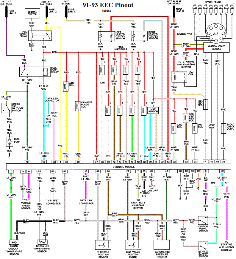
Complete computer, actuator & sensor wiring diagram for 91-93 Mass Air Mustangs
91-93_5.0_EEC_Wiring_Diagram.gif


See the following website for some help from Tmoss (diagram designer) & Stang&2Birds (website host) for help on 88-95 wiring; http://www.veryuseful.com/mustang/tech/engine/ Everyone should bookmark this site.

94-95 Mustang wiring diagrams
http://www.veryuseful.com/mustang/tech/engine/#95-95Diagrams

Complete computer, actuator & sensor wiring diagram for 88-91 Mass Air Mustangs
http://www.veryuseful.com/mustang/tech/engine/images/88-91_5.0_EEC_Wiring_Diagram.gif

Ignition switch wiring
http://www.veryuseful.com/mustang/tech/engine/images/IgnitionSwitchWiring.gif

Fuel, alternator, A/C and ignition wiring
http://www.veryuseful.com/mustang/tech/engine/images/fuel-alt-links-ign-ac.gif

O2 sensor wiring harness
http://www.veryuseful.com/mustang/tech/engine/images/mustangO2Harness.gif

Vacuum diagram 89-93 Mustangs
http://www.veryuseful.com/mustang/tech/engine/images/mustangFoxFordVacuumDiagram.jpg

HVAC vacuum diagram
http://www.veryuseful.com/mustang/tech/engine/images/Mustang_AC_heat_vacuum_controls.gif

TFI module differences & pin out
http://www.veryuseful.com/mustang/tech/engine/images/TFI_5.0_comparison.gif

Fuse box layout
http://www.veryuseful.com/mustang/tech/engine/images/MustangFuseBox.gif

Mustang 5.0 Lights and Radio schematic, by TMoss:
http://www.veryuseful.com/mustang/tech/engine/images/mustangFoxLights-Radio_diag.gif

87-92 power window wiring
http://www.veryuseful.com/mustang/tech/engine/images/mustang87-92 PowerWindowWiring.gif

93 power window wiring
http://www.veryuseful.com/mustang/tech/engine/images/mustang93PowerWindows.gif

T5 Cutaway showing T5 internal parts
http://www.veryuseful.com/mustang/tech/engine/images/5_Speed_Cutaway_Illustrated.jpg

Visual comparison of the Ford Fuel Injectors, picture by TMoss:
http://www.veryuseful.com/mustang/tech/engine/images/Ford_Injector_Guide.jpg

Convertible top motor wiring http://www.veryuseful.com/mustang/tech/engine/images/mustang88VertTopMotorCkt.gif

Engine mounted fuel injector harness
http://www.veryuseful.com/mustang/tech/engine/images/mustangEngineHarness.gif tang/tech/engine/images/mustang88VertTopMotorCkt.gif
 

Attachments

  • fuel-injector-wiring-harness-sensors-for-a-5-0-mustang-gif.63347.gif
    fuel-injector-wiring-harness-sensors-for-a-5-0-mustang-gif.63347.gif
    12.3 KB · Views: 301
  • 88-91_5.0_EEC_Wiring_Diagram.gif
    88-91_5.0_EEC_Wiring_Diagram.gif
    77 KB · Views: 343
  • 63833d1237100806-where-does-map-sensor-get-its-vacuum-100_3996.jpg
    63833d1237100806-where-does-map-sensor-get-its-vacuum-100_3996.jpg
    797.5 KB · Views: 546
Last edited:
I checked the wire on the map sensor. My tps orange wire is black with a white stripe on the car harness side. I don't have a orange wire at the map sensor but I do have a black with white stripe. The black with white stripe should be my 5 volt supply. I had 5 volts at the tps and at the map sensor and the car started fine. Shut the car off and it wouldn't start back. The tps orange wire then was showing 1.3 volts when it wouldn't start. It was also showing 1.3 volts at the map sensor as well. This tells me that since they are fed off the same circuit that I have a supply problem rather then wire problem. Any thoughts or help? Thanks
 
I updated the wiring diagram to show the correct year model range for your car-91-93 5.0 Mustang.
Click on any diagram to enlarge it for better viewing.

Look at the diagram and chase the wire back to the computer. Use the diagram I posted for the wire side of the computer wiring connector to locate the brown/white wire that is 5 volt VREF on you model car. Do a resistance check from the computer wiring connector to the MAP/Baro sensor brown/white wire. You should see less that 1 ohm. Wiggle the wires while you test them. Inspect the computer wiring connector pins to make sure that there aren't any broken wires or pins trying to come loose. Check the computer for loose pins as well.

Unless I am mistaken, the 5 volt VFREF is the same 5 volt power that supplies power for the computer's internal works. If it was going up and down like the TPS voltages, the car would not run and would die when the voltage dropped below 4.5 volts.