You need more help than what you have gotten so far; here's a start
Since you were able to dump the cores without resorting to unusual tricks, the PIN 46 signal ground inside the computer is OK. If it wasn't you wouldn't have gotten the codes to dump without some trickery.
The code 86 you alluded to is probably due to the Code 66 - MAF being bad. or a mismatch between the MAF sensor and the MAF housing. Fix that first and then chase the code 22. Once code 22 and 66 have been fixed, the code 86 should go away and the car will run much better.
Code 18 - SPOUT out or wiring fault - look for short to ground in SPOUT wiring going back to the computer. Possible bad TFI or defective 22 K resistor in the IDM wiring
Use a timing light to check the timing: remove the SPOUT and observe that the timing retards at least 4 degrees. Put the SPOUT back in place and observe that the spark advances at least 4 degrees.
This code can disable spark advance and reduce power and fuel economy.
Remove the passenger side kick panel and disconnect the computer connector.
There is a 10 MM bolt that holds it in place.
Disconnect the TFI module connector from the TFI and the measure the resistance between the yellow/lt green wire and ground. You should see greater than 100 K (100000) ohms.
Check the resistance from Pin 4 on the computer connector (dark green/yellow) and the dark green/yellow wire on the TFI connector. You should see 20-24 K Ohms (20,000-24,0000 ohms).
Resistor location: A big thanks to liljoe07 for this information:
Next measure the resistance between the yellow/lt green wire on the TFI module connector and Pin 36 on the computer connector. With the SPOUT plug in place, you should see less than 2 ohms.
The following is a view from the computer side of the computer connector.
This diagram is the wire side of the computer connector.
Diagram courtesy of Tmoss & Stang&2birds
MAP/BARO sensor operation and code 22
Revised 14-Nov-2014 to add wire colors for frequency & voltage testing and engine sensor wiring diagrams.
On a Speed Density car, the MAP/BARO sensor is connected to the intake manifold and acts to sense the manifold pressure. Lower vacuum inside the intake manifold when combined with more throttle opening measured by the TPS means more airflow through the engine. As airflow increases, fuel flow through the injectors needs to increase to keep the air/fuel ratio where it needs to be. When manifold vacuum increases, the engine is either decelerating or idling, and it needs to reduce the fuel flow through the injectors.
On a Mass Air car, the MAP/BARO sensor vents to open air and actually senses the barometric pressure due to changes in weather and altitude. Its purpose is to set a baseline for the computer to know the barometric pressure. As barometric pressure decreases, it leans out the fuel flow to compensate for less oxygen in the air. When the barometric pressure rises, it increases to add fuel since there is more oxygen in the air. The fuel requirements decrease as altitude increases, since the atmospheric pressure decreases.
Disconnecting the MAP or BARO sensor will set code 22.
Misconnecting the BARO sensor to vacuum on a Mass Air car will cause the computer to lean out the fuel mixture.
Code 22 or 126 MAP (vacuum) or BARO signal out of range. The MAP or BARO sensor is pretty much the same sensor for both Mass Air & Speed Density cars. The main difference is where it is connected. Mass Air cars vent it to the atmosphere, while Speed Density cars connect it to the intake manifold vacuum. Its purpose is to help set a baseline for the air/fuel mixture by sensing changes in barometric pressure. The MAP or BAP sensor puts out a 5 volt square wave that changes frequency with variations in atmospheric pressure. The base is 154 HZ at 29.92" of mercury - dry sunny day at sea level, about 68-72 degrees. You need an oscilloscope or frequency meter to measure it. There a very few DVM’s with a price tag under $40 that will measure frequency, but there are some out there.
Map sensor wiring:
black/white - ground
orange/white or +5 volts power
white/red signal out.
Measure the +5 volt supply using the orange/white and black/white wires
Measure the signal using the black/white and white/red wires.
The MAP/BARO sensor is mounted on the firewall behind the upper manifold on 86-93 Mustangs.
Baro or MAP test using a real frequency meter - run the test key on, engine off. The noise from the ignition system will likely upset the frequency meter. I used a 10 x oscilloscope probe connected from the frequency meter to the MAP/BAP to reduce the jitter in the meter's readout. And oscilloscope is very useful if you have access to one or know of someone who does. With an oscilloscope, you can see the waveform and amplitude.
If it is defective, your air/fuel ratio will be off and the car’s performance & emissions will suffer
Some basic checks you can make to be sure that the sensor is getting power & ground:
Note that all resistance tests must be done with power off. Measuring resistance with a circuit powered on will give false readings and possibly damage the meter.
Check the resistance between the black/white wire on the MAP/BARO sensor and then the black/white wire on the EGR and the same wire on the TPS. It should be less than 1 ohm. Next check the resistance between the black/white wire and the negative battery cable. It should be less than 1.5 ohm.
The following power on check requires you to turn the ignition switch to the Run position.
Use a DVM to check for 5 volts on the orange/white wire. If it is missing, look for +5 volts at the orange/white wire on the TPS or EGR sensors. Use the black/white wire for the ground for the DVM.
Diagrams courtesy of Tmoss & Stang&2birds
Complete computer, actuator & sensor wiring diagram for 88-91 Mass Air Mustangs
Complete computer, actuator & sensor wiring diagram for 91-93 Mass Air Mustangs
Code 66 or 157 MAF below minimum test voltage.
Revised 10-Feb-2014 to add 95-95 Mustang code 157 and 94-95 ECC diagram
Insufficient or no voltage from MAF. Dirty MAF element, bad MAF, bad MAF wiring, missing power to MAF. Check for missing +12 volts on this circuit. Check the two links for a wiring diagram to help you find the red wire for computer power relay switched +12 volts. Check for 12 volts between the red and black wires on the MAF heater (usually pins A & B). while the connector is plugged into the MAF. This may require the use of a couple of safety pins to probe the MAF connector from the back side of it.
Computer connector for 88-93 5.0 Mustangs
Diagrams courtesy of Tmoss and Stang&2Birds
ECC Diagram for 88-90 5.0 Mustangs
ECC Diagram for 91-93 5.0 Mustangs
94-95 Diagram for 94-95 5.0 Mustangs
There are three parts in a MAF: the heater, the sensor element and the amplifier. The heater heats the MAF sensor element causing the resistance to increase. The amplifier buffers the MAF output signal and has a resistor that is laser trimmed to provide an output range compatible with the computer's load tables. Changes in RPM causes the airflow to increase or decrease, changing the voltage output.. The increase of air across the MAF sensor element causes it to cool, allowing more voltage to pass and telling the computer to increase the fuel flow. A decrease in airflow causes the MAF sensor element to get warmer, decreasing the voltage and reducing the fuel flow.
The MAF element is secured by 2 screws & has 1 wiring connector. To clean the element, remove it from the MAF housing and spray it down with electronic parts cleaner or non-inflammable brake parts cleaner (same stuff in a bigger can and cheaper too).
89-90 Model cars: Measure the MAF output at pins C & D on the MAF connector (dark blue/orange and tan/light blue) or at pins 50 & 9 on the computer. Be sure to measure the sensor output by measuring across the pins and
not between the pins and ground.
91-95 Model cars: Measure the MAF output at pins C & D on the MAF connector light blue/red and tan/light blue) or at pins 50 & 9 on the computer. Be sure to measure the sensor output by measuring across the pins and
not between the pins and ground.
At idle = approximately .6 volt
20 MPH = approximately 1.10 volt
40 MPH = approximately 1.70 volt
60 MPH = approximately 2.10 volt
Check the resistance of the MAF signal wiring. Pin D on the MAF and pin 50 on the computer (dark blue/orange wire) should be less than 2 ohms. Pin C on the MAF and pin 9 on the computer (tan/light blue wire) should be less than 2 ohms.
There should be a minimum of 10K ohms between either pin C or D on the MAF wiring connector and pins A or B. Make your measurement with the MAF disconnected from the wiring harness.
Actually MAF pins C & D float with reference to ground. The signal output of the MAF is a differential amplifier setup. Pins C & D both carry the output signal, but one pin's output is inverted from the other. The difference in signal between C & D is what the computer's input circuit is looking for. The difference in the two outputs helps cancel out electrical noise generated by the ignition system and other components. Since the noise will be of the same polarity, wave shape and magnitude, the differential input of the computer electronically subtracts it from the signal. Then it passes the signal on to an Analog to Digital converter section inside the computer's CPU chip.
See the following website for some help from Tmoss (diagram designer) & Stang&2Birds (website host) for help on 88-95 wiring
http://www.veryuseful.com/mustang/tech/engine/
Ignition switch wiring
http://www.veryuseful.com/mustang/tech/engine/images/IgnitionSwitchWiring.gif
Fuel pump, alternator, ignition & A/C wiring
http://www.veryuseful.com/mustang/tech/engine/images/fuel-alt-links-ign-ac.gif
Computer,. actuator & sensor wiring
http://www.veryuseful.com/mustang/tech/engine/images/88-91_5.0_EEC_Wiring_Diagram.gif
Code 85 CANP solenoid - The Carbon Canister solenoid is inoperative or missing.
Revised 11 –Jan_2015 to add warning about vacuum leaks due to deteriorated hose or missing caps on vacuum lines when the solenoid is removed.
Check vacuum lines for leaks and cracks. Check electrical wiring for loose connections, damaged wiring and insulation. Check solenoid valve operation by grounding the gray/yellow wire to the solenoid and blowing through it.
The computer provides the ground for the solenoid. The red wire to the solenoid is always energized any time the ignition switch is in the run position.
If you disconnected the carbon canister and failed to properly cap the vacuum line coming from under the upper intake manifold, you will have problems. You will also have problems if the remaining hose coming from under the upper intake manifold or caps for the vacuum line are sucking air.
Charcoal canister plumbing - one 3/8" tube from the bottom of the upper manifold to the rubber hose. Rubber hose connects to one side of the canister solenoid valve. Other side of the solenoid valve connects to one side of the canister. The other side of the canister connects to a rubber hose that connects to a line that goes all the way back to the gas tank. There is an electrical connector coming from the passenger side injector harness near #1 injector that plugs into the canister solenoid valve. It's purpose is to vent the gas tank. The solenoid valve opens at cruse to provide some extra fuel. The canister is normally mounted on the passenger side frame rail near the smog pump pulley.
Connecting the gas tank vent line directly to the intake manifold will result in fuel vapor being constantly sucked into the intake manifold. There is unmetered fuel that the computer cannot adjust for. The result is poor idle and poor fuel economy.
It does not weigh but a pound or so and helps richen up the cruse mixture. It draws no HP & keeps the car from smelling like gasoline in a closed garage. So with all these good things and no bad ones, why not hook it up & use it?
The purge valve solenoid connector is a dangling wire that is near the ECT sensor and oil filler on the passenger side rocker cover. The actual solenoid valve is down next to the carbon canister. There is about 12"-16" of wire that runs parallel to the canister vent hose that comes off the bottom side of the upper intake manifold. That hose connects one port of the solenoid valve; the other port connects to the carbon canister.
The purge valve solenoid should be available at your local auto parts store.
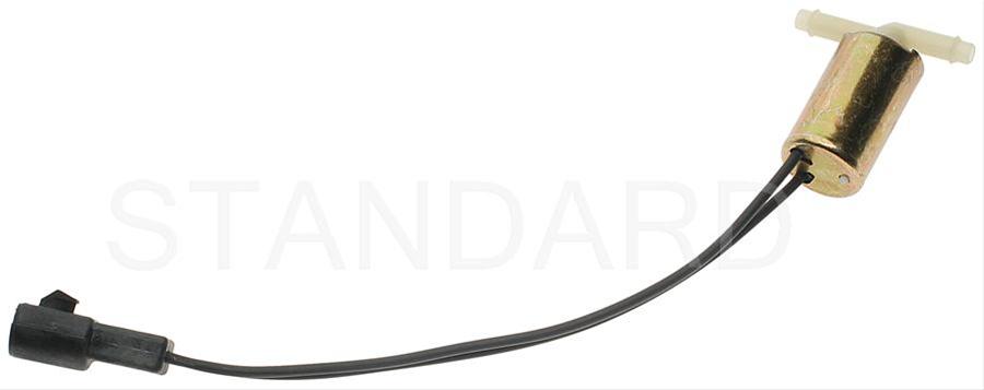
Purge valve solenoid:
The carbon canister is normally mounted on the passenger side frame rail near the smog pump pulley.
Carbon Canister:
Code 86 Adaptive fuel limit reached. The computer cannot adjust the fuel injector pulse duration enough to get the air/fuel mixture to achieve the perfect 14.7: 1 air/ fuel ratio at cruse. This may be an extreme rich or extreme lean condition. It can be due to a MAF/injector or MAF/computer mismatch, defective MAF (this will set code 66), fuel pressure set too high or bad injector(s), or a failed MAP/BARO sensor (this will set code 22).
Included in this problem are engines converted to MAF and the MAP/Baro sensor is still connected to the intake manifold: this will cause an extreme rich condition. MAF engines require you to let the MAP/Baro sensor vent to the open air.
Diagnosing the problem:
Check the O2 sensors – look for code 41/91 when you dump the codes.
Check the O2 sensor output at the computer: If the O2 sensors aren’t bad, this will help you determine if you have an extreme rich or extreme lean condition.
An O2 sensor reading that is always high and never switches to a low reading is an extreme rich condition.
An O2 sensor reading that is always low and never switches to a high reading is an extreme lean condition.
Testing the O2 sensors 87-93 5.0 Mustangs
Measuring the O2 sensor voltage at the computer will give you a good idea of how well they are working. You'll have to pull the passenger side kick panel off to gain access to the computer connector. Remove the plastic wiring cover to get to the back side of the wiring. Use a safety pin or paper clip to probe the connections from the rear.
Disconnect the O2 sensor from the harness and use the body side O2 sensor harness as the starting point for testing. Do not measure the resistance of the O2 sensor , you may damage it. Resistance measurements for the O2 sensor harness are made with one meter lead on the O2 sensor harness and the other meter lead on the computer wire or pin for the O2 sensor.
Backside view of the computer wiring connector:
87-90 5.0 Mustangs:
Computer pin 43 Dark blue/Lt green – LH O2 sensor
Computer pin 29 Dark Green/Pink – RH O2 sensor
The computer pins are 29 (LH O2 with a dark green/pink wire) and 43 (RH O2 with a dark blue/pink wire). Use the ground next to the computer to ground the voltmeter. The O2 sensor voltage should switch between .2-.9 volt at idle.
91-93 5.0 Mustangs:
Computer pin 43 Red/Black – LH O2 sensor
Computer pin 29 Gray/Lt blue – RH O2 sensor
The computer pins are 29 (LH O2 with a Gray/Lt blue wire) and 43 (RH O2 with a Red/Black wire). Use the ground next to the computer to ground the voltmeter. The O2 sensor voltage should switch between .2-.9 volt at idle.
Testing the O2 sensors 94-95 5.0 Mustangs
Measuring the O2 sensor voltage at the computer will give you a good idea of how well they are working. You'll have to pull the passenger side kick panel off to gain access to the computer connector. Remove the plastic wiring cover to get to the back side of the wiring. Use a safety pin or paper clip to probe the connections from the rear. The computer pins are 29 (LH O2 with a red/black wire) and 27 (RH O2 with a gray/lt blue wire). Use pin 32 (gray/red wire) to ground the voltmeter. The O2 sensor voltage should switch between .2-.9 volt at idle.
Fuel pressure OK, the injectors are not firing, OR one or more injectors stuck
open
Do a cylinder balance test: Warm the car's engine up to normal operating
temperature. With the Engine Off, Key OFF, use a jumper wire or paper clip to
put the computer into test mode. Start the engine and let it go through the
normal diagnostic tests, then quickly press the throttle to the floor. The
engine RPM should exceed 2500 RPM's for a brief second. The engine will shut
off power to each injector, one at a time. When it has sequenced through all
8 injectors, it will flash 9 or the number of the failing cylinder such as 22 for
cylinder #2. Quickly pressing the throttle again up to 2500 RPM’s will cause
the test to re-run with smaller qualifying figures. Do it a third time, and if the
same cylinder shows up, the cylinder is weak and isn’t putting out power like
it should. See the Chilton’s Shop manual for the complete test procedure
The red wire on each injector is powered up whenever the ignition switch is
in the Run position. The computer provides a ground to complete the circuit
and fire the injector. The injector
must have a ground to squirt fuel on
command. A short to ground in the injector return wiring can cause one or
more injectors to be continually open or triggered
A.) A Noid light available from Autozone, is one way to test
the injector wiring. If the light stays on constantly, either the wiring has a
short to ground or the computer has failed
B.) I like to use an old injector with compressed air applied to the
injector where the fuel rail would normally connect. I hook the whole thing
up, apply compressed air to the injector and stick it in a paper cup of soapy
water. When the engine cranks with the ignition switch on, if the injector
fires, it makes bubbles An injector stuck open will release a continual stream
of bubbles. Cheap if you have the stuff laying around, and works good too.
The same trick works great to find leaking injectors too.
The wiring for the injectors may have some bare spots in it causing the
injector to computer control wire to ground out. This would cause the
injector to remain on anytime the key was in the Run position. Remove the
injector wiring connectors from the injector. Note that each injector has one
red wire for power and a non red wire (wire some color other than red) for
computer controlled ground. With the key off, disconnect the computer
connector from the computer. Use an Ohmmeter between the non red wire
and ground. You should see more than 100000 (100K) ohms resistance.
Code 96 for 86-90 model 5.0 Mustang – KOEO- Fuel pump monitor circuit shows no power - Fuel pump relay or battery power feed was open - Power / Fuel Pump Circuits. The fuel pump lost power at some time while the ignition switch was in the run position. The main power feed to the pump is what is losing power.
Look for a failing fuel pump relay, bad connections or broken wiring. The fuel pump relay is located under the passenger seat.
On Mass Air Conversions, the signal lead that tells the computer that the fuel pump has power may not have been wired correctly.
See
http://www.stangnet.com/tech/maf/massairconversion.html
Look for power at the fuel pump - the fuel pump has a connector at the rear of the car with a pink/black wire and a black wire that goes to the fuel pump. The pink/black wire should be hot when the test connector is jumpered to the test position. . To trick the fuel pump into running, find the ECC test connector and jump the connector in the lower RH corner to ground.
86-90 Models:
Using the diagram, check the red/black wire from the fuel pump relay: you should see 12 volts or so. If not, check the inertia switch: on a hatch it is on the drivers side by the taillight. Look for a black rubber plug that pops out: if you don't find it, then loosen up the plastic trim. Check for voltage on both sides of the switch. If there is voltage on both sides, then check the Pink/black wire on the fuel pump relay: it is the power feed to the fuel pump. Good voltage there, then the fuel pump body to tank wiring harness connector is the likely culprit since it is getting power. No voltage there, check the Orange/Lt blue wire, it is the power feed to the fuel pump relay & has a fuse link in it. Good voltage there & at the Pink/black wire, swap the relay.
Keep in mind that the relay wiring and socket can also cause intermittent problems. Clean the relay socket with non-flammable brake parts cleaner or electrical contact cleaner. If you find damaged wiring at the relay socket, replacement pigtail socket assemblies are available at the auto parts stores. Be sure to solder the wires and cover the solder joints with heat shrink tubing if you replace the relay socket.
Now that you have replaced or repaired 1 or more sensors and their wiring, it is time to clear the codesinside the computer to give it a clean slate to write on.
How to clear codes.
Clearing the codes by pressing a button on the scan tool or disconnecting the test jumper used to start the code dump does not erase the “learned settings”. All it does is erase the stored codes in memory.
You must clear the codes anytime you replace any sensor. The following tells you how and is different from the method above
Clear the computer codes by disconnecting the battery negative terminal and turn the headlights on. Turn the headlights off and reconnect the all sensors including the MAF and anything else you may have disconnected. Then reconnect the battery negative cable.. This clears all spurious codes may have been generated while troubleshooting problems. It also clears the adaptive settings that the computer "learns" as it operates. Clearing the codes does not fix the code problems, it just gives you a clean slate to start recording what the computer sees happening.
Run the car for at least 30 minutes of driving and dump the codes again to assure that you have fixed the code problem or sensor problem. This is necessary for the computer to relearn the adaptive settings that the computer uses for proper operation. The engine may run rough at first, but should smooth out as it runs for the 15-20 minute learning period.
See the following website for some help from Tmoss (diagram designer) & Stang&2Birds (website host) for help on 88-95 wiring
http://www.veryuseful.com/mustang/tech/engine/ Everyone should bookmark this site.
Complete computer, actuator & sensor wiring diagram for 91-93 Mass Air Mustangs
http://www.veryuseful.com/mustang/tech/engine/images/91-93_5.0_EEC_Wiring_Diagram.gif
Complete computer, actuator & sensor wiring diagram for 88-91 Mass Air Mustangs
http://www.veryuseful.com/mustang/tech/engine/images/88-91_5.0_EEC_Wiring_Diagram.gif
Ignition switch wiring
http://www.veryuseful.com/mustang/tech/engine/images/IgnitionSwitchWiring.gif
Fuel, alternator, A/C and ignition wiring
http://www.veryuseful.com/mustang/tech/engine/images/fuel-alt-links-ign-ac.gif
O2 sensor wiring harness
http://www.veryuseful.com/mustang/tech/engine/images/mustangO2Harness.gif
Vacuum diagram 89-93 Mustangs
http://www.veryuseful.com/mustang/tech/engine/images/mustangFoxFordVacuumDiagram.jpg
HVAC vacuum diagram
http://www.veryuseful.com/mustang/tech/engine/images/Mustang_AC_heat_vacuum_controls.gif
TFI module differences & pin out
http://www.veryuseful.com/mustang/tech/engine/images/TFI_5.0_comparison.gif
Fuse box layout
http://www.veryuseful.com/mustang/tech/engine/images/MustangFuseBox.gif
87-92 power window wiring
http://www.veryuseful.com/mustang/tech/engine/images/mustang87-92 PowerWindowWiring.gif
93 power window wiring
http://www.veryuseful.com/mustang/tech/engine/images/mustang93PowerWindows.gif
T5 Cutaway showing T5 internal parts
http://www.veryuseful.com/mustang/tech/engine/images/5_Speed_Cutaway_Illustrated.jpg
Visual comparison of the Ford Fuel Injectors, picture by TMoss:
http://www.veryuseful.com/mustang/tech/engine/images/Ford_Injector_Guide.jpg