Lean Missfire

stangman11

Member
Feb 27, 2006
220
3
19
New Jersey
Ok guys got an odd condition that keeps happening with my87 fox. I will try to be as detailed with the story as possible and hopefully someone can point me in the right direction.

First off its an 87 GT stock with basic bolt on's and is still a speed density set up. The car was at a friends shop who was giving me a hand putting in the 3.73 gears. The car drove there sat over night and the next day wouldnt start. I was not around at the time and he figured it was the fuel pump. He ended up messing with the fuel pump harness connector right behind the tank and the rear bumper and said found some corrosion on the connector. He cleaned it up and the car started. Even with the connector and pins clean every now again randomly while driving even when easy on the throttle the motor will sharply bog down and at times when you lay into it just continue to miss and not get out of its own way. I dont know if its possibly high resistance in the connector even though its now clean or the pump is on its way out. The only other thing I noticed is if I notice the condition is happening and I shut the car down and fire it up again it will run normally again for a while then go back to the lean miss.

Just wanted to see if anyone else has ever experiences this and maybe has a direction for me to go.
 
  • Sponsors (?)


Dump the codes and look for codes 95 or 96

Dump the codes: Codes may be present even if the Check Engine Light (CEL) isn't on.

Dumping the computer diagnostic codes on 86-95 Mustangs

Revised 26-July-2011. Added need to make sure the clutch is pressed when dumping codes.

Codes may be present even if the check engine light hasn’t come on, so be sure to check for them.

Here's the way to dump the computer codes with only a jumper wire or paper clip and the check engine light, or test light or voltmeter. I’ve used it for years, and it works great. You watch the flashing test lamp or Check Engine Light and count the flashes.

Post the codes you get and I will post 86-93 model 5.0 Mustang specific code definitions and fixes. I do not have a complete listing for 94-95 model 5.0 Mustangs at this time.

Be sure to turn off the A/C, and put the transmission in neutral when dumping the codes. On a manual transmission car, be sure to press the clutch to the floor.
Fail to do this and you will generate a code 67 and not be able to dump the Engine Running codes.

Underhoodpictures007-01.jpg


Underhoodpictures010.jpg


If your car is an 86-88 stang, you'll have to use the test lamp or voltmeter method. There is no functional check engine light on the 86-88's except possibly the Cali Mass Air cars.

computer-self-test-connector-with-test-lamp-01-65-gif.55020


The STI has a gray connector shell and a white/red wire. It comes from the same bundle of wires as the self test connector.

89 through 95 cars have a working Check Engine light. Watch it instead of using a test lamp.

computer-self-test-connector-with-check-engine-light-01-65-gif.55021


The STI has a gray connector shell and a white/red wire. It comes from the same bundle of wires as the self test connector.


WARNING!!! There is a single dark brown connector with a black/orange wire. It is the 12 volt power to the under the hood light. Do not jumper it to the computer test connector. If you do, you will damage the computer.

What to expect:
You should get a code 11 (two single flashes in succession). This says that the computer's internal workings are OK, and that the wiring to put the computer into diagnostic mode is good. No code 11 and you have some wiring problems. This is crucial: the same wire that provides the ground to dump the codes provides signal ground for the TPS, EGR, ACT and Map/Baro sensors. If it fails, you will have poor performance, economy and driveablity problems

Some codes have different answers if the engine is running from the answers that it has when the engine isn't running. It helps a lot to know if you had the engine running when you ran the test.

Dumping the Engine Running codes: The procedure is the same, you start the engine with the test jumper in place. Be sure the A/C is off, and clutch (if present) is pressed to the floor, and the transmission is in neutral. You'll get an 11, then a 4 and the engine will speed up to do the EGR test. After the engine speed decreases back to idle, it will dump the engine running codes.

Trouble codes are either 2 digit or 3 digit, there are no cars that use both 2 digit codes and 3 digit codes.

Alternate methods:
For those who are intimidated by all the wires & connections, see Actron® for what a typical hand scanner looks like. Normal retail price is about $30 or so at AutoZone or Wal-Mart.

Or for a nicer scanner see Equus - Digital Ford Code Reader (3145) – It has a 3 digit LCD display so that you don’t have to count flashes or beeps.. Cost is $30.
 
Code 95 Key On, Engine not Running - the following test path is for 86-90 model Mustangs.

The 95 code is because at one time or another, the fuel pump relay hiccupped and didn't provide power the pump when the computer told it to run. Sometimes this is a one time thing, other times it is a no run or runs poorly condition.

attachment.php


Using the diagram, check the red/black wire from the fuel pump relay: you should see 12 volts or so. If not, check the inertia switch: on a hatch it is on the driver’s side by the taillight. Look for a black rubber plug that pops out: if you don't find it, then loosen up the plastic trim. Check for voltage on both sides of the switch. If there is voltage on both sides, then check the Pink/black wire on the fuel pump relay: it is the power feed to the fuel pump. No voltage there, check the Orange/Lt blue wire, it is the power feed to the fuel pump relay & has a fuse link in it. If there is good voltage there & at the Pink/black wire, swap the relay.

Some Mass Air conversions neglect to run the extra fuel pump wire, and they always have a 95 code. See http://www.stangnet.com/tech/maf/massairconversion.html for more information on the Mass Air wiring conversion.

See the following website for some help from Tmoss (diagram designer) & Stang&2Birds (website host) for help on 88-95 wiring http://www.veryuseful.com/mustang/tech/engine/ Everyone should bookmark this site.

Ignition switch wiring
http://www.veryuseful.com/mustang/tech/engine/images/IgnitionSwitchWiring.gif

Fuel, alternator, A/C and ignition wiring
http://www.veryuseful.com/mustang/tech/engine/images/fuel-alt-links-ign-ac.gif

Complete computer, actuator & sensor wiring diagram for 88-91 Mass Air Mustangs
http://www.veryuseful.com/mustang/tech/engine/images/88-91_5.0_EEC_Wiring_Diagram.gif

Complete computer, actuator & sensor wiring diagram for 91-93 Mass Air Mustangs
http://www.veryuseful.com/mustang/tech/engine/images/91-93_5.0_EEC_Wiring_Diagram.gif

Vacuum diagram 89-93 Mustangs
http://www.veryuseful.com/mustang/tech/engine/images/mustangFoxFordVacuumDiagram.jpg

HVAC vacuum diagram
http://www.veryuseful.com/mustang/tech/engine/images/Mustang_AC_heat_vacuum_controls.gif

TFI module differences & pinout
http://www.veryuseful.com/mustang/tech/engine/images/TFI_5.0_comparison.gif

Fuse box layout
http://www.veryuseful.com/mustang/tech/engine/images/MustangFuseBox.gif

Code 96 – KOEO- Fuel pump monitor circuit shows no power - Fuel pump relay or battery power feed was open - Power / Fuel Pump Circuits. The fuel pump lost power at some time while the ignition switch was in the run position. The main power feed to the pump is what is losing power.

Look for a failing fuel pump relay, bad connections or broken wiring. The fuel pump relay is located under the passenger seat. On Mass Air Conversions, the signal lead that tells the computer that the fuel pump has power may not have been wired correctly.
See http://www.stangnet.com/tech/maf/massairconversion.html

attachment.php


Look for power at the fuel pump - the fuel pump has a connector at the rear of the car with a pink/black wire and a black wire that goes to the fuel pump. The pink/black wire should be hot when the test connector is jumpered to the test position. . To trick the fuel pump into running, find the ECC test connector and jump the connector in the lower RH corner to ground.
attachment.php


86-90 Models:
Using the diagram, check the red/black wire from the fuel pump relay: you should see 12 volts or so. If not, check the inertia switch: on a hatch it is on the drivers side by the taillight. Look for a black rubber plug that pops out: if you don't find it, then loosen up the plastic trim. Check for voltage on both sides of the switch. If there is voltage on both sides, then check the Pink/black wire on the fuel pump relay: it is the power feed to the fuel pump. Good voltage there, then the fuel pump body to tank wiring harness connector is the likely culprit since it is getting power. No voltage there, check the Orange/Lt blue wire, it is the power feed to the fuel pump relay & has a fuse link in it. Good voltage there & at the Pink/black wire, swap the relay.

Keep in mind that the relay wiring and socket can also cause intermittent problems. Clean the relay socket with non-flammable brake parts cleaner or electrical contact cleaner. If you find damaged wiring at the relay socket, replacement pigtail socket assemblies are available at the auto parts stores. Be sure to solder the wires and cover the solder joints with heat shrink tubing if you replace the relay socket.


fuel-pump-wiring-89-90-5-0-mustang-jpg.55493
 
Thanks for the diagram, I actually picked up a code reader on the way home from work and did my testing.

The only code I had KOEO was for the air pump which is disconnected to I expected that. The KOER were the main issues I have one code for the MAP sensor, for both Oxygen sensors and the TPS. I did a quick tap test on the TPS and the car stumbled so I ran out and bought a new one and installed it. I will find out tomorrow on the way to work to see how much of an improvement it made. I wont be shocked if it still stumbles because all of those issues can causes the same concern.

Ill fill you in on any new news tomorrow.
 
What sort of voltages did you get when testing or setting the TPS sensor?

Setting the TPS at .98 volt is a Bozo Internet Myth.When the computer powers up and initializes the TPS sensor, whatever it reads is the zero starting point for it. In other words your .98 volt becomes 0 volts and the computer watches for increases in voltage from that point upward.

Setting the TPS: you'll need a good Digital Voltmeter (DVM) to do the job. Set the TPS voltage at .5- 1.1 range. Because of the variables involved with the tolerances of both computer and DVM, I would shoot for somewhere between .6 and 1.0 volts. Unless you have a Fluke or other high grade DVM, the second digit past the decimal point on cheap DVM’s is probably fantasy. Since the computer zeros out the TPS voltage every time it powers up, playing with the settings isn't an effective aid to performance or drivability. The main purpose of checking the TPS is to make sure it isn't way out of range and causing problems.


Wire colors & functions:
Orange/white = 5 volt VREF from the computer
Dark Green/lt green = TPS output to computer
Black/white = Signal ground from computer

TPS troubleshooting steps:
1.) Use the Orange/white & Black white wires to verify the TPS has the correct 5 volts source from the computer.
2.) Use the Dark Green/lt green & Black/white wires to set the TPS base voltage. Try this... All you need is less than 1.0 volt at idle and more than 4.25 at Wide Open Throttle (WOT). You'll need a voltmeter with a 1 or 3 volt low scale to do the job.

The Orange/White wire is the VREF 5 volts from the computer. You use the Dark Green/Lt green wire (TPS signal) and the Black/White wire (TPS ground) to set the TPS. Use a pair of safety pins to probe the TPS connector from the rear of the connector. You may find it a little difficult to make a good connection, but keep trying. Put the safety pins in the Dark Green/Lt green wire and Black/White wire. Make sure the ignition switch is in the Run position but the engine isn't running. Set the voltmeter on the 2 volt range if it doesn’t auto range.

Here’s a TPS tip I got from NoGo50

When you installed the sensor make sure you place it on the peg right and then tighten it down properly. Loosen the back screw a tiny bit so the sensor can pivot and loosen the front screw enough so you can move it just a little in very small increments. I wouldn’t try to adjust it using marks.

(copied from MustangMax, Glendale AZ)

A.) Always adjust the TPS and Idle with the engine at operating temp. Dive it around for a bit if you can and get it nice and warm.

B.) When you probe the leads of the TPS, do not use an engine ground, put the ground probe into the lead of the TPS. You should be connecting both meter probes to the TPS and not one to the TPS and the other to ground.

C.) Always reset the computer whenever you adjust the TPS or clean/change any sensors. I just pull the battery lead for 10 minutes.

D.) The key is to adjust the TPS voltage and reset the computer whenever the idle screw is changed.

The TPS is a variable resistor, must like the volume control knob on a cheap radio. We have all heard them crackle and pop when the volume is adjusted. The TPS sensor has the same problem: wear on the resistor element makes places that create electrical noise. This electrical noise confuses the computer, because it expects to see a smooth increase or decrease as the throttle is opened or closed.

TPS testing: most of the time a failed TPS will set code 23 or 63, but not always. Use either an analog meter or a DVM with an analog bar graph and connect the leads as instructed above. Turn the ignition switch to the Run position, but do not start the engine. Note the voltage with the throttle closed. Slowly open the throttle and watch the voltage increase smoothly, slowly close the throttle and watch the voltage decrease smoothly. If the voltage jumps around and isn’t smooth, the TPS has some worn places in the resistor element. When the throttle is closed, make sure that the voltage is the same as what it was when you started. If it varies more than 10%, the TPS is suspect of being worn in the idle range of its travel.

TPS will not go below 1 volt
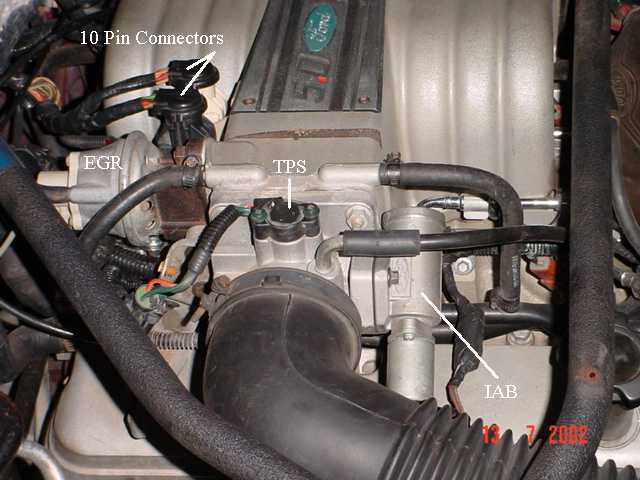
Engine mounted sensor circuit: Check the resistance between the black/white wire on the TPS and battery ground. It should be less than 1.5 ohms. Higher resistance than 1.5 ohms indicates a problem with the 10 pin connector, computer or the splice inside the main harness where the wire from the 10 pin connectors joins the rest of the black/white wire.

attachment.php


See the graphic for the location of the 10 pin connectors:
Diagram courtesy of Tmoss & Stang&2birds

TPS_IAB_Pic.jpg


See the graphic for the 10 pin connector circuit layout.
salt-pepper-10-pin-connectors-65-jpg.68512


Unplug the white 10 pin connector to do some resistance testing. It is good time to clean the connector pins and examine the connector for corrosion, broken wire or other damage. See http://oldfuelinjection.com/?p=85 for help in this department.

If the resistance on the TPS Black/White wire and pin 1 of the white engine fuel injector harness 10 pin connector, is more than 1.0 ohm, you have bad connection or broken wiring. Repeat the test using the pin 1 of the white body side 10 pin connector and battery ground. You should have less that 1.5 ohm. More than that is a damaged signal ground inside the computer or bad connections or wiring.
[/b][/b]
 
Sorry for the delay I didnt actually check the voltage on the new sensor because unlike the original that came off it didnt have the slots where the bolts were housed allowing me to adjust it. It simply had two holes no slots so I had assumed the newer designed sensors you didnt have to adjust. But I will check the voltage as soon as I am able.
 
Ok I have the day off and before it started raining I went out and checked the TPS voltage they are perfect .7 closed and 4.78 at WOT. Any other suggestions of where to turn next? Still no fuel codes but is it possible to still have a intermittent relay problem and have no codes?