Ok I forgot to mention I have 30 psi of fuel pressure with the vacuum on and 41 with it off. I am getting computer codes 14,18,95,96. Forgot to add this in my original message
Since you have replaced some parts, clear the codes and drive the car before dumping them again.
How to clear codes.
Clearing the codes by pressing a button on the scan tool or disconnecting the test jumper used to start the code dump does not erase the “learned settings”. All it does is erase the stored codes in memory, which is what you want to do at this time.
You must clear the codes anytime you replace any sensor. The following tells you how and is different from the method above
Clear the computer codes by disconnecting the battery negative terminal and turn the headlights on. Turn the headlights off and reconnect the all sensors including the MAF and anything else you may have disconnected. Then reconnect the battery negative cable. This clears all spurious codes may have been generated while troubleshooting problems. It also clears the adaptive settings that the computer "learns" as it operates. Clearing the codes does not fix the code problems, it just gives you a clean slate to start recording what the computer sees happening.
Run the car for at least 30 minutes of driving and dump the codes again to assure that you have fixed the code problem or sensor problem. This is necessary for the computer to relearn the adaptive settings that the computer uses for proper operation. The engine may run rough at first, but should smooth out as it runs for the 15-20 minute learning period.
Code 14 - Ignition pickup (PIP) was erratic – the Hall Effect sensor in the distributor is failing. Bad sensor, bad wiring, dirty contacts. Factory tach will sometimes read erratically.
Revised 8-Apr-2017 to correct SPOUT problem symptoms wording
PIP Sensor functionality, testing and replacement:
The PIP is a Hall Effect magnetic sensor that triggers the TFI and injectors. There is a shutter wheel alternately covers and uncovers a fixed magnet as it rotates. The change in the magnetic field triggers the sensor. A failing PIP sensor will often set code 14 in the computer. They are often heat sensitive, increasing the failure rate as the temperature increases.
Some simple checks to do
before replacing the PIP sensor or distributor:
You will need a Multimeter or DVM with good batteries: test or replace them before you get started. You may also need some extra 16-18 gauge wire to extend the length of the meter’s test leads.
Visual check first: look for chaffed or damaged wiring and loose connector pins in the TFI harness connector.
Check the IDM wiring – dark green/yellow wire from the TFI module to pin 4 on the computer. There is a 22K Ohm resistor in the wiring between the TFI and the computer. Use an ohmmeter to measure the wire resistance from the TFI to the computer. You should see 22,000 ohms +/- 10%.
Check the PIP wiring - dark blue from the TFI module to pin 56 on the computer. Use an ohmmeter to measure the wire resistance from the TFI to the computer. You should see 0.2-1.5 ohms.
Check the SPOUT wiring – yellow/lt green from the TFI module to pin 36 on the computer. Use an ohmmeter to measure the wire resistance from the TFI to the computer. You should see 0.2-1.5 ohms.
Check the black/orange wire from the TFI module to pin 16 on the computer. Use an ohmmeter to measure the wire resistance from the TFI to the computer. You should see 0.2-1.5 ohms.
Check the red/green wire; it should have a steady 12-13 volts with the ignition switch on and the engine not running.
Check the red/blue wire; it should have a steady 12-13 volts with the ignition switch in Start and the engine not running. Watch out for the fan blades when you do this test, since the engine will be cranking.
If you do not find any chaffed or broken wires, high resistance connections or loose pins in the wiring harness, replace the PIP sensor or the distributor.
The PIP sensor is mounted in the bottom of the distributor under the shutter wheel. In stock Ford distributors, you have to press the gear off the distributor shaft to get access to it to replace it. Most guys just end up replacing the distributor with a reman unit for about $75 exchange
PIP problems & diagnostic info
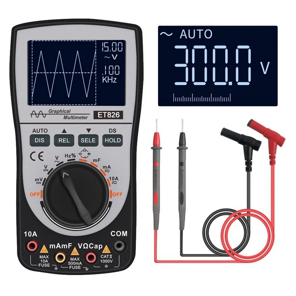
Spark with the SPOUT out, but not with the SPOUT in suggests a PIP problem. The PIP signal level needs to be above 6.5 volts to trigger the computer to pulse the fuel injectors, but only needs to be 5.75 volts to trigger the TFI module. Hence with a weak PIP signal, and the SPOUT in, you could get spark but no injector pulse. You will need an oscilloscope or graphing DVM to measure the output voltage since it is not a straight DC voltage.
If you want to see what's happening in real time, see 2 in 1 Digital Oscilloscope MT8206 Multimeter with Analog Bar Graph ET826
Smarter Shopping, Better Living! Aliexpress.com

www.aliexpress.com
Code 18 - SPOUT out or wiring fault - look for short to ground in SPOUT wiring going
back to the computer. Possible bad TFI or defective 22 K resistor in the IDM wiring
Revised 24 June 2019 to add comment about the need of thermal paste on TFI mounting surface.
Use a timing light to check the timing: remove the SPOUT and observe that the timing retards at least 4 degrees. Put the SPOUT back in place and observe that the spark advances at least 4 degrees.
This code can disable spark advance and reduce power and fuel economy.
Remove the passenger side kick panel and disconnect the computer connector.
It takes a 10 MM socket to remove the bolt that holds the connector in place..
Disconnect the TFI module connector from the TFI and the measure the resistance between the yellow/lt green wire and ground.
You should see greater than 100 K (100000) ohms.
Check the resistance from Pin 4 on the computer connector (dark green/yellow) and the dark green/yellow wire on the TFI connector. You should see 20-24 K Ohms (20,000-24,0000 ohms).
Resistor location: A big thanks to liljoe07 for this information:
Check over by the brake booster. It’s not in the harness on the TFI, it’s on the main part of the harness over by the plugs that connect to the dash harness. About 6" or so from that, going back toward the EEC.
If I remember right, the resistor is covered in a shrink tubing that is sealed to the wires. So, you won’t be able see any markings. The shrink tubing is labeled though. It's a 22 KΩ, 1/2 watt resistor.
Here is the location.
Next measure the resistance between the yellow/lt green wire on the TFI module connector and Pin 36 on the computer connector. With the SPOUT plug in place, you should see less than 2 ohms.
The following is a view from the computer side of the computer connector.
This diagram is the wire side of the computer connector.
Diagram courtesy of Tmoss & Stang&2birds
If you replace the or remove the TFI, clean the mounting surface off with alcohol and apply a fresh coat of thermal paste to the TFI mounting surface. Fail to do this and the TFI will quit working once the engine warms up.
Code 95 Key On, Engine not Running - the following test path is for 86-90 model Mustangs.
The 95 code is because at one time or another, the fuel pump relay hiccupped and didn't provide power the pump when the computer told it to run. Sometimes this is a one time thing, other times it is a no run or runs poorly condition.
Using the diagram, check the red/black wire from the fuel pump relay: you should see 12 volts or so. If not, check the inertia switch: on a hatch it is on the driver’s side by the taillight. Look for a black rubber plug that pops out: if you don't find it, then loosen up the plastic trim. Check for voltage on both sides of the switch. If there is voltage on both sides, then check the Pink/black wire on the fuel pump relay: it is the power feed to the fuel pump. No voltage there, check the Orange/Lt blue wire, it is the power feed to the fuel pump relay & has a fuse link in it. If there is good voltage there & at the Pink/black wire, swap the relay.
Some Mass Air conversions neglect to run the extra fuel pump wire, and they always have a 95 code. See
http://www.stangnet.com/tech/maf/massairconversion.html for more information on the Mass Air wiring conversion.
See the following website for some help from Tmoss (diagram designer) & Stang&2Birds (website host) for help on 88-95 wiring
http://www.veryuseful.com/mustang/tech/engine/ Everyone should bookmark this site.
Ignition switch wiring
Fuel, alternator, A/C and ignition wiring
Complete computer, actuator & sensor wiring diagram for 88-91 Mass Air Mustangs
Complete computer, actuator & sensor wiring diagram for 91-93 Mass Air Mustangs
Vacuum diagram 89-93 Mustangs
HVAC vacuum diagram
TFI module differences & pinout
Fuse box layout
Revised 11 Oct 2021 to add troubleshooting tip to distinguish a fuel pump relay problem from an ignition switch problem.
Code 96 for 86-90 model 5.0 Mustang – KOEO- Fuel pump monitor circuit shows no power - Fuel pump relay or battery power feed was open - Power / Fuel Pump Circuits. The fuel pump lost power at some time while the ignition switch was in the run position. The main power feed to the pump is what is losing power.
Look for a failing fuel pump relay, bad connections or broken wiring. The fuel pump relay is located under the passenger seat.
On Mass Air Conversions, the signal lead that tells the computer that the fuel pump has power may not have been wired correctly.
See
http://www.stangnet.com/tech/maf/massairconversion.html .
Look for power at the fuel pump - the fuel pump has a connector at the rear of the car with a pink/black wire and a black wire that goes to the fuel pump. The pink/black wire should be hot when the test connector is jumpered to the test position. To trick the fuel pump into running, find the ECC test connector and jump the connector in the lower RH corner to ground.
This code is often intermittent; the only clue is that the engine shuts off or stumbles while you are driving. This limits your ability to troubleshoot the problem when it happens, so you have to rely on the code dump to clue you in on what’s happening.
The radio, heater or A/C are not affected. If the radio, heater or A/C turn off at the same time, the engine stumbles, look for a failing ignition switch.
86-90 Models:
Using the diagram, check the red/black wire from the fuel pump relay: you should see 12 volts or so. If not, check the inertia switch: on a hatch it is on the driver’s side by the taillight. Look for a black rubber plug that pops out: if you don't find it, then loosen up the plastic trim. Check for voltage on both sides of the switch. If there is voltage on both sides, then check the Pink/black wire on the fuel pump relay: it is the power feed to the fuel pump. Good voltage there, then the fuel pump body to tank wiring harness connector is the likely culprit since it is getting power. No voltage there, check the Orange/Lt blue wire, it is the power feed to the fuel pump relay & has a fuse link in it. Good voltage there & at the Pink/black wire, swap the relay.
Keep in mind that the relay wiring and socket can also cause intermittent problems. Clean the relay socket with non-flammable brake parts cleaner or electrical contact cleaner. If you find damaged wiring at the relay socket, replacement pigtail socket assemblies are available at the auto parts stores. Be sure to solder the wires and cover the solder joints with heat shrink tubing if you replace the relay socket.
The code 96 may be intermittent. I have the same code and have replaced the relay, so I'm going to have to do some work to find a more complete troubleshooting process and a solid fix.