
I am looking for the correct vacuum line diagram for a late 1990s Ford Explorer upper intake (non-EGR) I am using on my 87' Mustang GT 5.0 HO My AC and smog pump have been deleted. Does anyone know what the vacuum line sequence should be on this set-up I have. I just installed GT40P heads and the matching upper/lower GT40 Explorer Intake. Or should I look at the stock upper intake off my HO 5.0 and use that as a reference point? Thank you
You are using an out of date browser. It may not display this or other websites correctly.
You should upgrade or use an alternative browser.
You should upgrade or use an alternative browser.
Vacum Line Diagram For Later Explorer Intake On A 5.0 Foxbody
- Thread starter DM87GT
- Start date
-
Sponsors (?)
mikestang63
SN Certified Technician
The one in front will go to your cannister. One from the rear goes to the FPR, The larger one goes to the vacuum tree on the firewall. Since you removed the EGR, you don't need that line and can cap it off. You also need to hook up the PCV hose.
Mike, thank you for the details! Under the GT40 upper intake, there are 2 small ports I believe to be the EGR ports. I can cap those off, and hook up my PCV hose, along with connecting the FPR, and the line to the canister and vacuum tree. Since I am using the GT40P heads which I just had redone with new valves and Ford Racing spring kit ( since I am using the stock HO .444 lift cam), there are no adjustments for the stock 1.6 rocker arms since the heads are pedestal mount type heads. Once the roller lifters are seated on the flat spot on the cam, torque the 7/16 rocker bolts down to 20 ft. lbs. Is this procedure correct, or do shims have to be used to achieve the correct height on the push rod and valves? Thanks again
There are actually a few different vacuum line configurations used on the Explorer upper. The early ones mimic the 5.0 HO upper almost exactly while the later ones change slightly.
Without seeing pics, hard to know which you have, but basically you just want to copy the 5.0 HO setup, and that might mean plugging some of the holes or adding 1 as well. You may have to swap the threaded nipple from the 5.0 HO intake over as well depending on the explorer upper you have
Without seeing pics, hard to know which you have, but basically you just want to copy the 5.0 HO setup, and that might mean plugging some of the holes or adding 1 as well. You may have to swap the threaded nipple from the 5.0 HO intake over as well depending on the explorer upper you have
Mustang5L5, Thanks so much for the update on the vacuum line sequence. My upper and lower GT40 Intake including the matching GT40P heads came off a 1998 Ford Explorer 5.0 This upper and lower intake is the non-EGR intake, although my original 5.0 HO set-up does have the EGR. I have no plans to use the EGR as I bought a EGR delete plate for the 70mm throttle body. This vacuum line configuration is pretty basic, and shouldn't pose a problem. I have attached a pic of the backside of the upper GT40 intake showing the vacuum ports. If there is anything else I need to do than just the basics to make this work, let me know and I'll resolve any issues that may arise, hopefully none will! I have attached a couple other pics of the upper and lower assembled with the a 1/2 cooling block to help keep the incoming air cool. Hope the pics help. Thank you again for your expertise!
Attachments


mikestang63
SN Certified Technician
I have to ask- why are you deleting the EGR? It costs no hp and removing it will not only throw codes, but also a CEL unless you get a tune done. It's not as simple as putting a block off plate on.

You would suggest to keep the EGR on the motor, and would would the EGR spacer work on the GT40 upper intake? I see no reason why, the throttle body and EGR spacer all have the same bolt pattern. But.......my GT40 Intake is the non-EGR, which means internal EGR? Thanks again Mike.
On a non egr intake, you really have no choice. You'll just have to live with the CEL on to turn off the egr function unless you get a custom tune. With the light on the function is disabled.
My intake is the later Explorer intake with the external EGR, which has no boss to be drilled for ACT sensor on the manifold. Just hope I'm not running into problems here.
Just install it and live with the CEL on in the dash.
One day, if you ever get a tune, have them turn off the EGR function to turn off the CEL.
Mike, I have the later GT40 upper and lower intake (external EGR). The GT40 intake is installed on the car and running. I tried to figure out the vacuum line sequence, and the car won't idle at first start up. It surges up and down then dies. When the engine reaches operating temperature, it will have a smoother idle and will stay running with my foot off the gas pedal. I kept the original EGR next to the throttle body, but plugged off both of the small coolant lines going into the throttle body. I am certain I have no vacuum leaks as the throttle body, IAC and upper and lower intake have all new Felpro gaskets. I set the TPS at .94 which is good, but I just can't figure out why it surges then dies at first start when the engine is cold.There are actually a few different vacuum line configurations used on the Explorer upper. The early ones mimic the 5.0 HO upper almost exactly while the later ones change slightly.
Without seeing pics, hard to know which you have, but basically you just want to copy the 5.0 HO setup, and that might mean plugging some of the holes or adding 1 as well. You may have to swap the threaded nipple from the 5.0 HO intake over as well depending on the explorer upper you have


So you'll need to do a little modification to match the 5.0 HO intake.
Are you up to a little drill and tapping?
Gotta wait til the AM to respond. Laptop at 1% power so gotta log off.
Are you up to a little drill and tapping?
Gotta wait til the AM to respond. Laptop at 1% power so gotta log off.
I hooked up all the vacuum lines correctly I believe, starting with the PCV, the FPR, brake power booster vacuum, and the line that goes to the vacuum tree. The only vacuum I didn't hook up was the charcoal canister vacuum line. The 2 small EGR ports under the upper intake I capped off since I have bypassed the EGR. My ACT plug is just sitting under the upper intake. Since the walls of the later Explorer intakes are relatively thin, I didn't want to drill and tap at the #5 runner, instead I could relocate it to the air-intake tube. I am running a CAI by the way. As I said before, I don't think I have any vacuum leaks to speak of, so hoping the problem is the vacuum lines under the upper intake are not routed properly. My 70mm throttle body is new, the TPS is new and adjusted to .94, I cleaned the IAC and cleaned the connections. My PIP in the distributor looks OK, as I have heard that could be one of the causes, but just want to pinpoint where the problem is, instead of going round in circles making assumptions!So you'll need to do a little modification to match the 5.0 HO intake.
Are you up to a little drill and tapping?
Gotta wait til the AM to respond. Laptop at 1% power so gotta log off.
Be sure to cap off the charcoal canister vacuum line if it isn't hooked up to the canister solenoid valve and canister.
Charcoal canister plumbing - one 3/8" tube from the bottom of the upper manifold to the rubber hose. Rubber hose connects to one side of the canister solenoid valve. Other side of the solenoid valve connects to one side of the canister. The other side of the canister connects to a rubber hose that connects to a line that goes all the way back to the gas tank. There is an electrical connector coming from the passenger side injector harness near #1 injector that plugs into the canister solenoid valve. It's purpose is to vent the gas tank. The solenoid valve opens at cruse to provide some extra fuel. The canister is normally mounted on the passenger side frame rail near the smog pump pulley.

It does not weigh but a pound or so and helps richen up the cruse mixture. It draws no HP & keeps the car from smelling like gasoline in a closed garage. So with all these good things and no bad ones, why not hook it up & use it?
The purge valve solenoid connector is a dangling wire that is near the ECT sensor and oil filler on the passenger side rocker cover. The actual solenoid valve is down next to the carbon canister. There is about 12"-16" of wire that runs parallel to the canister vent hose that comes off the bottom side of the upper intake manifold. That hose connects one port of the solenoid valve; the other port connects to the carbon canister.
The purge valve solenoid should be available at your local auto parts store.
Purge valve solenoid:

The carbon canister is normally mounted on the passenger side frame rail near the smog pump pulley.
Carbon Canister:

The ACT (Air Charge Temp) sensor will probably need to be moved. The GT 40 lower manifold isn't drilled & tapped for it to go into the intake like the stock manifold was. There is a boss cast into the GT 40, but a machine shop will have to drill & tap the new manifold. If you want to DIY it, use a 37/64 drill bit with a 1/2" shank and a 3/8" pipe tap. Those 2 items may not be easy to get, especially the 37/64" drill bit with a reduced 1/2" shank. Either way you will have to have the lower intake off the engine to do it.
The best spot for the ACT is the air box if you don't do the drill and tap thing. You get to cut and splice the 2 ACT wires in order to make them long enough to reach the air box. Solder the wire extensions on the existing wires & use heat shrink tubing to cover the splices. Offset the place where you cut the wires so that you don't have a big bulge when you put heat shrink over the 2 wires to cover & protect them. The air box gets a hole (5/8" or so) for the ACT drilled about 1 1/4" down & 1/1/4" in on the front top side near the upper radiator hose. A brass fitting nut from Home Depot or Ace Hardware secures the ACT into the air box.
If you are very clever, you will find that the ACT connector comes apart so that you can remove the pins. A very small screwdriver releases the lock in the front of the center insert, while another small screwdriver inserted in the back pushes it out. Once the center insert is out of the connector shell, the pins come out easily. New pins are available from AutoZone in a $5 electrical pin kit for Fords. Crimping the pins on the extender wires saves you from having to splice them twice: once to put the connector on and once to extend the wires.
6 ft black 18 gauge wire
6 ft green 18 gauge wire
6 ft 1/4" heat shrink tubing
1 ft 3/16" heat shrink tubing
Measure the 2 extender wires & cut them to length, crimp one set of pins on them. Then mate up the extender pins with the wiring harness & slide the 3/16" heat shrink tubing over them & shrink the tubing. Then slide the 1/4" heat shrink tubing over the pair of wires and shrink the tubing. When you are done you'll have about 1" of wire left without heat shrink tubing on it to strip & crimp the new pins on. Stick the new pins in the old connector shell, assemble it and you are done. It looks as good as factory. Some wire loom can be used to enhance the "Factory Look".


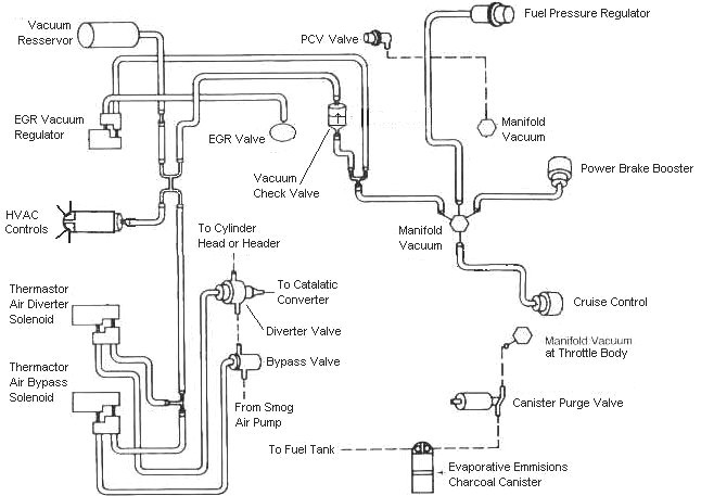
Vacuum line connections:
One large vacuum line from the upper front goes to the carbon canister
One large vacuum line from the rear goes to the vacuum tree.
One small line in the front feeds the Smog pump solenoid control valves on the rear of the passenger side wheel well..
One small line in the rear goes to the fuel pressure regulator.
One small line in the rear goes to the EGR suction regulator.
One large line in the rear goes to the PVC valve.
Diagram courtesy of Tmoss & Stang&2birds - Typical Vacuum Routing for a Fox stang 5.0:
Want to wear yourself out with info on the Explorer intake manifolds? See http://www.stangnet.com/mustang-for...d-gt-40-intake-thread-56k-dont-bother.551505/
Charcoal canister plumbing - one 3/8" tube from the bottom of the upper manifold to the rubber hose. Rubber hose connects to one side of the canister solenoid valve. Other side of the solenoid valve connects to one side of the canister. The other side of the canister connects to a rubber hose that connects to a line that goes all the way back to the gas tank. There is an electrical connector coming from the passenger side injector harness near #1 injector that plugs into the canister solenoid valve. It's purpose is to vent the gas tank. The solenoid valve opens at cruse to provide some extra fuel. The canister is normally mounted on the passenger side frame rail near the smog pump pulley.
It does not weigh but a pound or so and helps richen up the cruse mixture. It draws no HP & keeps the car from smelling like gasoline in a closed garage. So with all these good things and no bad ones, why not hook it up & use it?
The purge valve solenoid connector is a dangling wire that is near the ECT sensor and oil filler on the passenger side rocker cover. The actual solenoid valve is down next to the carbon canister. There is about 12"-16" of wire that runs parallel to the canister vent hose that comes off the bottom side of the upper intake manifold. That hose connects one port of the solenoid valve; the other port connects to the carbon canister.
The purge valve solenoid should be available at your local auto parts store.
Purge valve solenoid:
The carbon canister is normally mounted on the passenger side frame rail near the smog pump pulley.
Carbon Canister:
The ACT (Air Charge Temp) sensor will probably need to be moved. The GT 40 lower manifold isn't drilled & tapped for it to go into the intake like the stock manifold was. There is a boss cast into the GT 40, but a machine shop will have to drill & tap the new manifold. If you want to DIY it, use a 37/64 drill bit with a 1/2" shank and a 3/8" pipe tap. Those 2 items may not be easy to get, especially the 37/64" drill bit with a reduced 1/2" shank. Either way you will have to have the lower intake off the engine to do it.
The best spot for the ACT is the air box if you don't do the drill and tap thing. You get to cut and splice the 2 ACT wires in order to make them long enough to reach the air box. Solder the wire extensions on the existing wires & use heat shrink tubing to cover the splices. Offset the place where you cut the wires so that you don't have a big bulge when you put heat shrink over the 2 wires to cover & protect them. The air box gets a hole (5/8" or so) for the ACT drilled about 1 1/4" down & 1/1/4" in on the front top side near the upper radiator hose. A brass fitting nut from Home Depot or Ace Hardware secures the ACT into the air box.
If you are very clever, you will find that the ACT connector comes apart so that you can remove the pins. A very small screwdriver releases the lock in the front of the center insert, while another small screwdriver inserted in the back pushes it out. Once the center insert is out of the connector shell, the pins come out easily. New pins are available from AutoZone in a $5 electrical pin kit for Fords. Crimping the pins on the extender wires saves you from having to splice them twice: once to put the connector on and once to extend the wires.
6 ft black 18 gauge wire
6 ft green 18 gauge wire
6 ft 1/4" heat shrink tubing
1 ft 3/16" heat shrink tubing
Measure the 2 extender wires & cut them to length, crimp one set of pins on them. Then mate up the extender pins with the wiring harness & slide the 3/16" heat shrink tubing over them & shrink the tubing. Then slide the 1/4" heat shrink tubing over the pair of wires and shrink the tubing. When you are done you'll have about 1" of wire left without heat shrink tubing on it to strip & crimp the new pins on. Stick the new pins in the old connector shell, assemble it and you are done. It looks as good as factory. Some wire loom can be used to enhance the "Factory Look".
Vacuum line connections:
One large vacuum line from the upper front goes to the carbon canister
One large vacuum line from the rear goes to the vacuum tree.
One small line in the front feeds the Smog pump solenoid control valves on the rear of the passenger side wheel well..
One small line in the rear goes to the fuel pressure regulator.
One small line in the rear goes to the EGR suction regulator.
One large line in the rear goes to the PVC valve.
Diagram courtesy of Tmoss & Stang&2birds - Typical Vacuum Routing for a Fox stang 5.0:
Want to wear yourself out with info on the Explorer intake manifolds? See http://www.stangnet.com/mustang-for...d-gt-40-intake-thread-56k-dont-bother.551505/
Last edited:
Thanks for the info. and posting of the diagram! Since I installed the GT40 Explorer upper and lower intake , I checked over and over the vacuum lines under the upper intake and all lines are where they should be! Now, when I start the car, my idle will surge up and down. On a cold start, I have to feather the gas so the engine doesn't stall. Once the engine reaches operating temperature, it idles on it's own but still surges. I clean the IAC with carb and choke cleaner and seemed to help a little, but did not resolve the problem. I adjusted my TPS but the idle still surges. MAP sensor maybe or a bad IAC?
In case you haven't seen this before...
You guys with idle/stall problems could save a lot of time chasing your tails if you would go through the Surging Idle Checklist. Over 50 different people contributed information to it. The first two posts have all the fixes, and steps through the how to find and fix your idle problems without spending a lot of time and money. I continue to update it as more people post fixes or ask questions. You can post questions to that sticky and have your name and idle problem recognized. The guys with original problems and fixes get their posts added to the main fix.
It's free, I don't get anything for the use of it except knowing I helped a fellow Mustang enthusiast with his car. At last check, it had more than 134,000 hits, which indicates it does help fix idle problems quickly and inexpensively.
Thanks again for the much needed info. I managed to resolve a vacuum hose leak and the idle seems to not surge as much, but the idle is still surging a little. I did the base idle reset numerous times and adjusted my TPS at .94 I also have a new H-pipe with new o2 sensors. I am running the GT40 upper/lower intake and have the EGR disconnected including the small coolant lines from the EGR spacer. Will the TPS be damaged from the heat since the small coolant lines are disconnected, thinking my TPS may be going bad. Thanks
Similar threads
- Replies
- 21
- Views
- 2K
- Replies
- 22
- Views
- 1K
- Replies
- 2
- Views
- 275
- Replies
- 8
- Views
- 1K